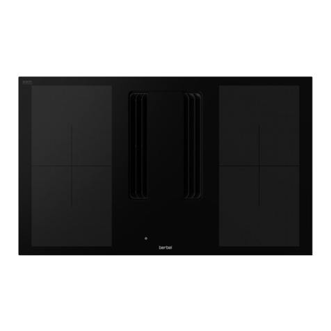
Berbel Panorama BKF 90 iPP User manual

EN Induction hob
Downline Panorama
EN Operating and installation instructions for the models
BKF 90 iPP
6006113_0

2
6006113_0 – 12.11.2021
Document information
Operating and installation instructions for:
yInduction hob BKF 90 iPP
yOriginal manual.
yPart of the product.
yCopyright protected.
yDuplications, re-printing and distribution only with
permission.
ySubject to alteration.
Safety information
DDANGER!
Notes with the word DANGER warn of a hazardous situation
that results in serious injuries or death.
DWARNING!
Notes with the word WARNING warn of a hazardous situation
that could result in serious injuries or death.
DCAUTION!
Notes with the word CAUTION warn of a situation that could
result in minor injuries.
DATTENTION!
Notes with the word ATTENTION warn of a situation that
could result in damage to property or to the environment.
Symbol clarification - text
☞Handling requirement
yListing
DReference to another point in this document
Reference to other documents that should be observed
Symbol clarification - illustrations
x
A
B
1.
2.
Highlighting of the parts involved in the action with
shading
1. Handling steps with numbering
APart designations with upper case characters
xDimensions with lower case characters or units in mm
Movement and direction arrows

3
6006113_0 – 12.11.2021
EN
Table of contents
1. Safety information ............................ 4
1.1 Proper intended use . . . . . . . . . . . . . . . . . . . . . 4
1.2 Authorised target groups . . . . . . . . . . . . . . . . . . 4
1.3 General safety instructions . . . . . . . . . . . . . . . . . 5
2. Product information ........................... 6
2.1 Product overview . . . . . . . . . . . . . . . . . . . . . . . 6
2.2 Scope of delivery . . . . . . . . . . . . . . . . . . . . . . . 6
2.3 Technical data . . . . . . . . . . . . . . . . . . . . . . . . . 6
2.3.1 Hob...........................................6
2.3.2 Cooking zones ................................6
3. Installation .................................... 7
3.1 Safety instructions for installation. . . . . . . . . . . . . 7
3.2 Requirements for the installation location . . . . . . . 7
3.3 Installation procedure . . . . . . . . . . . . . . . . . . . . 8
3.3.1 Preparation for installation ....................8
3.3.2 Unpack the device ............................8
3.3.3 Check dimensions ............................9
3.3.4 Installing the device.........................10
3.3.5 Establish electrical power supply ............11
3.3.6 Check and carry out commissioning ........ 11
4. Operation ....................................12
4.1 Safety information for operation . . . . . . . . . . . . .12
4.2 Cooking with induction . . . . . . . . . . . . . . . . . . .13
4.3 Control panel . . . . . . . . . . . . . . . . . . . . . . . . .13
4.4 Operation of the hob . . . . . . . . . . . . . . . . . . . .16
4.4.1 Count down function .......................17
4.4.2 Pause function ..............................17
4.4.3 Recall function ..............................17
4.4.4 Locking function ............................18
4.4.5 Extraction operating mode.................. 18
4.5 Operation of the cooking zones . . . . . . . . . . . . .19
4.5.1 Power level function ........................ 19
4.5.2 Boost and double boost function ...........19
4.5.3 Bridge function ............................. 20
4.5.4 Grill function ................................20
4.5.5 Head chef function. . . . . . . . . . . . . . . . . . . . . . . . . . 20
4.5.6 Automatic rapid heat-up function...........21
4.5.7 Simmer function ............................21
4.5.8 Automatic pot recognition function.........21
4.5.9 Beep function............................... 21
4.5.10 “Pot speed test” function ....................22
4.6 Operation of the extractor hood . . . . . . . . . . . . .23
4.6.1 Fan power ..................................23
4.6.2 Lift function.................................24
4.6.3 Synchronisation............................. 24
4.6.4 Effect lighting ............................... 24
4.6.5 Hob lighting ................................ 24
4.6.6 Run-on function ............................ 24
4.6.7 Ceiling connection with effect lighting ...... 25
4.6.8 Extraction mode / recirculated air mode
changeover .................................25
4.6.9 Filter filling indicator ........................25
4.6.10 Window contact switch ..................... 25
4.6.11 AutoRun ....................................25
5. Cleaning .....................................26
5.1 Safety information for cleaning . . . . . . . . . . . . . .26
5.2 Cleaning procedures. . . . . . . . . . . . . . . . . . . . .26
6. Maintenance .................................27
6.1 Safety instructions for maintenance . . . . . . . . . . .27
6.2 Fault rectification . . . . . . . . . . . . . . . . . . . . . . .27
7. Dismounting .................................29
8. Disposal ......................................30
8.1 Dispose of packaging . . . . . . . . . . . . . . . . . . . .30
8.2 Dispose of the device . . . . . . . . . . . . . . . . . . . .30
9. Contact. . . . . . . . . . . . . . . . . . . . . . . . . . . . . . . . . . . . . . . 31

4
Safety information
6006113_0 – 12.11.2021
1. Safety information
1.1 Proper intended use
The device is designed for normal domestic cooking, frying
and heating of foods.
The device is intended exclusively for private domestic use.
It is only permitted to use the device when it is in technically
flawless condition and after correct installation.
Any other use shall be considered improper use.
Reading and observing this manual are also part of the
proper use of the device.
1.2 Authorised target groups
Electrical work only to be undertaken by qualified electricians
per DIN VDE 0100. Requirements on qualified electricians:
yKnowledge of the basics of electrics.
yKnowledge of country-specific regulations and standards
(e.g. in Germany, DIN VDE 0100, part 701).
yKnowledge of the applicable safety regulations.
yKnowledge of the relevant legal requirements for gas
installations (e.g. in Germany the technical rules for gas
installations TRGI).
yKnowledge of this manual.
Installation and repair only by qualified specialist personnel.
Requirements on qualified specialist personnel:
yKnowledge of the regulations on safety at work.
yKnowledge of fastening systems.
yBasic knowledge of ventilation systems.
yExperienced in using electrical and mechanical tools.
yAbility to read technical drawings.
yKnowledge of this manual.
Operation, cleaning and maintenance by the user.
Requirements for the user:
yKnowledge of this manual.
There are separate requirements for the following users:
yChildren from 8 years and older.
yPersons with restricted physical, sensory or mental
capabilities.
yPersons with a lack of experience and knowledge.
These users are only permitted to carry out operation,
cleaning and maintenance. Special requirements:
yUsers are supervised.
yUsers are instructed with regard to safe use of the device.
yUsers understand the hazards involved with the device.
yChildren may not play with the device.
Particular details for children under eight years of age:
yThe hob becomes hot during operation. The hob remains
hot for a while after it has been switched off. Children
must be kept away from the hob until all risks of burns
can be ruled out.
yObjects which can be interesting to children must not be
stored in the vicinity of the hob.
yPot and pan handles must be positioned on the hob such
that they cannot be reached by children.
yChildren must be monitored continuously if they are in
the vicinity of the hob.

5
Safety information
6006113_0 – 12.11.2021
EN
1.3 General safety instructions
DWARNING!
Hazard through a disregard of the operating and
installation instructions!
This manual contains important information for the safe
handling of the device. Separate reference is made to
possible hazards.
☞Read through this manual thoroughly.
☞Follow the safety instructions in this manual.
☞Store the manual in an accessible location.
Naked flames can damage the device and can cause fires.
yDo not flambé on or near the device.
yNo unattended deep frying on or near the device.
The use of the device is forbidden under the following
circumstances:
yIn potentially explosive atmospheres.
yIf the device or individual components are damaged.
yIn the event of unauthorised alterations or changes to the
device.
yIf liquid has penetrated the device.
yWhen heavily soiled.
yFor children under 8 years old and persons who would
not be able to properly assess the hazards associated with
handling the device.
The manufacturer accepts no liability for damage occurring in
the following circumstances:
yDisregard of this manual.
yImproper use of the device.
yImproper installation and handling of the device.
yUse of the device by unauthorised target groups.
yBypassing safety equipment on the device.
yThe use of spare parts (e.g. mains cables) that were not
produced or approved by the manufacturer.
Further safety instructions can be found in the respective
relevant chapters of this manual.
D“3.1 Safety instructions for installation” (page 7).
D“4.1 Safety information for operation” (page 12).
D“5.1 Safety information for cleaning” (page 26).
D“6.1 Safety instructions for maintenance” (page 27).

6
Product information
6006113_0 – 12.11.2021
2. Product information
2.1 Product overview
B
A
1234
A Hob with four cooking zones
B Control panel
2.2 Scope of delivery
A
BC
A Hob with connection cable
B Sealing strip
C Height compensation plates, thickness 0.5/1.0/1.5/2.0 mm
AutoRun module (only with BKF 90 iPP-AR)
Observe the installation instructions for the AutoRun
module.
2.3 Technical data
2.3.1 Hob
BKF90iPP
Connection voltage 230 V ~ / 50/60 Hz
Total power 17400 W
Power consumption of the hob 2176.4 Wh/kg
Width 900 mm
Depth 400 mm
Height 50 mm
Net weight 10 kg
Specifications for the model (e.g. serial number, year of
construction) can be found on the ratings plate.
2.3.2 Cooking zones
1234
Dimensions 200 x
225.5 mm
200 x
225.5 mm
207.5 x
225.5 mm
207.5 x
225.5 mm
min. pot base
diameter 100 mm 100 mm 100 mm 100 mm
Output 12100 W 2100 W 1850 W 1850 W
Output
Boost 12650 W 2650 W 2300 W 2300 W
Double-boost
output 13700 W 3700 W 3000 W 3000 W
Power
consumption
per kg 2
172.5
Wh/kg
182.2
Wh/kg
175.4
Wh/kg
175.4
Wh/kg
Standardised
cookware
category
D C B B
Bridge function yes yes no no
1Outputs can vary depending on shape, size and quality of
the cookware.
2Specifications according to EU Regulation 66/2014.

7
Installation
6006113_0 – 12.11.2021
EN
3. Installation
3.1 Safety instructions for installation
DWARNING!
Hazard through disregard of the installation instructions!
This chapter contains important information for the safe
installation of the device.
☞Read through this chapter carefully before installing the
device.
☞Follow the safety instructions.
☞Carry out the installation as described.
yInstallation only by qualified specialist personnel.
D“1.2 Authorised target groups” (page 4).
yElectrical work must only be undertaken by qualified
electricians.
D“1.2 Authorised target groups” (page 4).
yThe hob and other parts that can be touched must be
allowed to cool prior to installation.
yStore the film or other parts of the packaging in a location
which is inaccessible to children.
yThe device must be in an undamaged and fault-free
condition prior to installation.
yCables must not be kinked, crushed or damaged.
yNever open the fan housing.
yIt is not permissible to attach further components
(e.g. panels, air ducts) to the device.
yThe power supply voltage must match the voltage
information quoted on the ratings plate.
D“2.3 Technical data” (page 6).
yEnsure that the power supply is stable and remains so
prior to the installation.
Connect the power supply only when instructed to do so
in the installation instructions.
Observe the safety information in the documentation for
the hob.
3.2 Requirements for the installation location
DWARNING!
Risk of death due to improper installation!
Disregard of the ambient conditions can lead to hazardous
situations, e.g. in the handling of electrical power or gas.
☞Make sure that the requirements for the installation
location are complied with.
yDo not install in potentially explosive atmospheres.
yMake sure that the building electrical supply is properly
earthed.
yThe power supply voltage present must match the
voltage information quoted on the ratings plate.
yThe customer must supply a means of connection to the
voltage supply in the installation area.
yAn all-pole isolating device (with a contact gap of at least
3 mm) must be provided.
yUse of an extension cable for connection to the voltage
supply is not permitted.
yThe device must only be installed next to cabinets or
walls on one side in accordance with Type Y protection
against the risk of fire. Furniture or devices on the other
side must not be higher than the hob.
yThe distance from the device to a wall or furniture to the
side must be at least 40 mm.
yThe distance between the hob and cabinets above the
hob must be at least 600 mm.
yAir circulation must be ensured for sufficient ventilation of
the device:
yVentilation outlet opening at least 120 cm2(e.g. in the
rear wall of the cabinet).
yMinimum gap beneath the device of 20 mm.
yDo not install in an enclosed cabinet.
yThe device must not be installed above the following
devices:
yOven without fan
yDishwasher
yClothes dryer
yThe work top must be installed with heat-resistant
adhesive (75 °C), sealed with special paint, silicone rubber
or cast resin.
yWall trim used in conjunction with installation must be
heat-resistant.
yThe device must remain accessible at all times for
maintenance work.
yIf necessary for the installation, only use suitable hob
protection grates or hob covers.
☞Please consult your dealer or customer services.
Country-specific, legal provisions must be observed.

8
Installation
6006113_0 – 12.11.2021
3.3 Installation procedure
Short overview:
1. Preparation for installation
2. Unpack the device
3. Check dimensions
4. Installing the device
5. Establish electrical power supply
6. Check and carry out commissioning
3.3.1 Preparation for installation
The device is designed for installation in furniture structures.
The installation sequence may vary, depending on the local
conditions.
☞Familiarise yourself with the installation situation and the
associated documents.
yDevice and instructions.
yAccessories.
yInstallation location.
yOrder documents.
yDimensions, position and alignment of the
components.
With induction hob BKF 90 iPP-AR:
Observe the installation instructions for the AutoRun
module.
☞Assemble the tools and materials required:
ySet-down area (e.g. trestle)
yFolding rule or measuring tape
yPencil
ySpirit level
yPhillips screwdriver PH2
yProtective material (e.g. thick cardboard) for the hob
and the worktops
☞Keep the installation area free of objects that could be in
the way or that could be damaged.
☞Make sure that the hob and other parts that could be
touched have cooled down.
☞Ensure that the power supply is switched off and remains
so. Connect the power supply only when instructed to do
so in the installation instructions.
3.3.2 Unpack the device
DATTENTION!
Hazard of glass breaking or other damage due to
incorrect handling!
The device and its surfaces can be damaged when being
unpacked or transported.
☞Do not cut into the protective cardboard packaging.
☞Keep objects that could scratch the device far away from
it (e.g. tools, belt buckles).
☞Unpack the device and all accompanying parts carefully.
☞Set the device down with the hob facing upwards on a
firm, clean and protective surface (e.g. thick cardboard).
☞Check the device and its constituent parts for damage.
☞Check the scope of delivery is complete.
D“2.2 Scope of delivery” (page 6).
If parts are missing or damaged:
☞Please consult your dealer or customer services.
☞Remove the packaging material and the protective film.
D“8.1 Dispose of packaging” (page 30).

9
Installation
6006113_0 – 12.11.2021
EN
3.3.3 Check dimensions
To determine the dimensions of the product, refer to the
order documents.
Flush installation
ab
x1
z
y
x2
Cutaway
Width (a) 862 + 2 mm
Depth (b) 380 + 2 mm
Corner radius R5
Milled recess
Width (x1) 12 mm
Depth (x2) 21 mm
Height (y) 3 mm
Outer dimensions 904 x 404 mm
Corner radius R5
Work top Height (z) > 10 mm
Counter-top installation
z
ab
Cutaway Width (a) 862 + 2 mm
Depth (b) 380 + 2 mm
Work top Height (z) > 10 mm
☞Check the dimensions.
D“2.3 Technical data” (page 6).
☞Ensure that the work top is suitable for the hob
installation.

10
Installation
6006113_0 – 12.11.2021
3.3.4 Installing the device
DWARNING!
Danger of injuries through improper handling!
Installation of the device requires a great deal of physical
exertion due to its size and weight. If the device falls down,
serious injuries are possible.
☞Install the device with two persons.
☞Ensure stable footing during installation.
☞Ensure that no other people are in the working area.
DATTENTION!
Danger of property damage through improper handling!
Installation of the device requires a great deal of physical
exertion due to its size and weight. If the device falls, the
device, kitchen furnishings and other objects could be
damaged.
☞Cover the working surface.
☞Keep the installation area clear.
The instructions for installation variants with a hob frame
must be observed. The following step is omitted.
2 mm
☞Remove the protective film from the sealing strip.
☞Adhere the seal on the underside of the hob, leaving a
2 mm gap from the outer edge.
☞Apply the sealing strip on all sides under the hob.
☞Check that the inserted hob is at the correct height.
If necessary, position the appropriate height
compensation plates below the sealing strip.

11
Installation
6006113_0 – 12.11.2021
EN
☞Seal the cut surface of the work top with suitable material
(heat resistant to 75 °C – e.g. special paint, silicone rubber
or cast resin).
For the material used, the worktop manufacturer’s
instructions must be followed.
☞Place the hob into the specified position in the lower
cabinet from above.
3.3.5 Establish electrical power supply
DWARNING!
Risk of death due to electric shock!
Touching live parts can cause an electric shock, burns or
death.
☞Ensure that the voltage supply is and remains
disconnected while the following work is in progress.
☞Observe the voltage specifications on the ratings plate.
☞Connect the device to the power supply provided by the
customer. The junction box is located on the underside of
the device.
Connection possibilities:
y400 V ~ / 50/60 Hz – 2P+N
NL1L2
45 123
Cable H 05 VV - F, H 05 RR - F,
Diameter 4 x 2.5 mm2,
Fuse 16 A
y230 V ~ / 50/60 Hz – 1P+N
(optional, not compatible with AutoRun module)
NL1
45 123
Cable H 05 VV - F, H 05 RR - F,
Diameter 3 x 4.0 mm2,
Fuse 40 A
☞Route the cables so that they are not kinked, crushed or
damaged and do not come into contact with hot parts of
the device.
☞Make sure that the device can be disconnected on all
poles from the electricity supply after installation.
After switching on the power supply, the device is ready for
operation.
3.3.6 Check and carry out commissioning
DATTENTION!
Risk of disruptions due to moisture in the device!
If the device is moved from a cold environment into a hot
one, condensation may form inside.
☞Wait about 2-3 hours before bringing the device into
service.
☞Ensure that the device is accessible for maintenance work
at all times.
☞Check that an all-pole isolating device (min. 3 mm contact
gap) is present.
☞Check that the mains cable and the electrical connection
cable are not kinked, crushed or damaged.
☞Make sure that the protective film is removed.
☞Check the correct functioning of the device.
D“4. Operation” (page 12).

12
Operation
6006113_0 – 12.11.2021
4. Operation
4.1 Safety information for operation
DWARNING!
Hazard through a disregard of the operating
instructions!
This chapter contains important information for the safe
operation of the device.
☞Read through this chapter carefully before operating the
device.
☞Follow the safety instructions.
yOperation only by authorised users.
D“1.2 Authorised target groups” (page 4).
yNo operation permitted by children under 8 years old and
persons who would not be able to properly assess the
hazards associated with handling the device.
yParticular details for children in the household must be
observed.
D“1.2 Authorised target groups” (page 4).
Information for use of the hob:
yWhen in use, the hob and other parts that could be
touched can become very hot. There is a risk of burning.
yDo not place heat-sensitive objects on the hot hob.
yDo not use during a fire or when there is an imminent
danger of fire (e.g. a smell of gas).
yDo not flambé. Fire hazard.
yDeep-frying must not take place unattended. Overheated
grease and oil can ignite.
yGrease residues should be removed. Grease residues pose
a fire hazard.
yNever extinguish fire on the hob with water. Risk of
explosion. Suffocate fire on the hob (e.g. with a fire
extinguishing blanket).
yDo not operate the device with a time switch or separate
remote controls.
yDo not use the device when damaged (e.g. broken glass).
yDo not use the hob as a work or storage surface.
yDo not use pots or pans with rough or damaged bottoms.
Grains of sand can also cause scratches.
yDo not use synthetic containers or aluminium vessels.
These containers can melt.
yDo not heat up closed containers (e.g. canned preserves).
The containers can burst due to overpressure.
yDo not heat up empty cookware.
yDo not place hot cookware on the control unit.
The electronics can be damaged as a result.
yDo not place metallic objects on the hob, because they
can become hot during use.
The automatic pot recognition can cause metallic objects
to be heated without this being noticed.
ySharp and hard objects (e.g. pot edges) can damage the
glass on the hob due to impact or falling.
yIf there is a drawer under the hob:
yDo not store flammable objects (e.g. spray cans).
yCutlery bins contained therein must be resistant to
heat.
yThe device must be switched off after use.
Sugar, plastic, aluminium foil and similar materials must
not come into contact with the hot hob. These materials
can melt, adhere or cause damage (e.g. cracks or breaks).
However, if these materials do come into contact with the
hot hob:
☞Turn off the device.
☞Remove the materials while they are still hot. There is a
risk of burns because the hob is hot.
The device is designed for combination with an extractor
hood from the manufacturer. The functions of the extractor
hood can be controlled by this device via a radio link.
Observe the extractor hood instructions.

13
Operation
6006113_0 – 12.11.2021
EN
4.2 Cooking with induction
In comparison to other types of hob (e.g. ceramic or gas),
there are a few peculiarities that must be observed when
using an induction hob.
DWARNING!
Risk of burns on hot parts!
The heating time can be very short with induction hobs.
The hob, cookware and the prepared food can become
quickly hot.
☞Avoid contact with hot parts.
☞Monitor the device during the cooking process.
Information for induction hobs:
yDo not use copper, brass, glass, aluminium, porcelain
or stainless steel cookware without magnetic bottoms,
because they are not suitable.
yDo not use magnetic objects (e.g. data carriers, credit
cards) near the device. Because the device works with
a magnetic field, the function of these objects can be
impaired.
Even if the device is working perfectly and the cookware is
suitable for induction hobs, the following noises may arise
during cooking:
yHumming, whistling, buzzing, clicking.
Possible causes:
yWhen set at high power levels.
yWhen using cookware with bottoms made of different
materials.
yIf the hob fan is in operation.
yTriggered by switching processes, e.g. the automatic
detection of cookware. This function can be switched off.
D“4.5.8 Automatic pot recognition function” (page 21).
These noises are normal and do not indicate any limitation of
the device or cookware.
4.3 Control panel
The device is controlled via the control panel, which consists
of six control groups located beneath the four cooking zones.
B
A
1 2 3 4
DEFC
A Operation of cooking zone 1
B Operation of cooking zone 2
C Operation of the extractor hood
D Operation of cooking zone 3
E Operation of cooking zone 4
F Operation of the hob in general
The control panel consists of sensor buttons. Each button
must be pressed to execute a specific action. Execution
of the action is confirmed by an acoustic signal and a
corresponding display.
Only the functions that are available in the menu or during
the cooking process are displayed.
Activated functions or cooking zones light up brightly.
A slider control is available for operating each of the cooking
zones. Each marking stands for a power level from 0 to 9.
The slider can be used as follows:
yDirect selection of the desired output by tapping a
specific level.
ySwiping movement to the right in order to increase the
output of the device or the adjusted value.
ySwiping movement to the left in order to decrease the
output of the device or the adjusted value.
The following functions of the cooking zones and extractor
hood are accessible via the menu buttons. The menu level
changes after the menu button is pressed. The symbols of
the functions available for this operating group are displayed.
In order to execute a function, the corresponding position
under the symbol on the slider must be touched.

14
Operation
6006113_0 – 12.11.2021
General functions and displays for the hob
ON / OFF
3x 7-segment display
Hob - Count down
Lock
Decrease
Increase
Extraction operating mode
Pause / Recall
Functions and displays for the hob
7-segment display of the cooking zone
Bridge function (only available on cooking
zones 1 and 2)
Cooking zone - count down
Menu button for cooking zones 1, 2, 3
Menu level 1 of cooking zones 1, 2, 3
Menu level 2 of cooking zones 1, 2, 3
Menu button for cooking zone 4
Menu level 1 of cooking zone 4
Menu level 2 of cooking zone 4
Menu level 3 of cooking zone 4
Slider

15
Operation
6006113_0 – 12.11.2021
EN
Menu level 1
Low power level
High power level
Boost and double boost
Menu level 2
Grill (function only available on cooking
zones 1 and 2)
Head chef (function only available on cooking
zone 4)
Automatic rapid heat-up
Simmer
Menu level 3 - only available on cooking zone 4 and if no
cooking zone is active (all power levels = 0)
Automatic pot recognition
Volume
Pot Speed Test
Functions and displays for the extractor hood
7-segment display of extraction
Menu button
Menu level 1
Menu level 2
“Lower” function 1
Synchronisation 1
Decrease
Effect lighting 1
Hob lighting 1
Run-on function 1
Increase
Multifunction button 1 (e.g. for ceiling
connection with effect lighting)
“Raise” function 1
Recirculated air mode, filter filling indicator,
window contact switch
1Whether the function can be executed depends on the
extractor hood.

16
Operation
6006113_0 – 12.11.2021
4.4 Operation of the hob
DWARNING!
Risk of burns on hot parts!
The hob, cookware and the prepared foot can become very
hot while working with the device. The heating time can be
very short with induction hobs.
☞Avoid contact with hot parts.
☞Monitor the device during the cooking process.
For optimum use of the hob:
☞Make sure that the hob is clean and clear of deposits.
☞Make sure that the base of the cookware used is clean.
☞Lift the cookware before moving it into a different
position.
☞Use cookware that is sufficiently large to avoid spilling
over.
☞Do not use the hob for peeling, cutting or setting
ingredients aside.
☞Make sure that sugar, plastic, aluminium foil and similar
materials do not come into contact with the hot hob.
If they do, remove them immediately.
☞Observe the instructions for cleaning the hob.
D“5. Cleaning” (page 26).
To switch the device on:
☞Press the button for 1 second.
yAll cooking zones are set to menu level 1
and ready for use.
yWhen connected to an extractor hood,
the extraction is ready for use.
If no input takes place or if no cooking zone is
active (all power levels = 0).
yThe device switches off after 20 seconds.
yOther buttons or indicators go out.
yThe operating group of the extractor hood
remains switched on when functions of
the extractor hood are still active
(e.g. run-on function).
Display after switching on:
The cooking zone is selected with the
corresponding buttons or via the automatic
pot recognition.
☞Press the display of a cooking zone or
move the cookware to the cooking zone.
yThe 7-segment display lights up brightly.
yFurther entries only apply for the selected
cooking zone.
☞Choose a power level by tapping or
swiping the slider.
yThe cooking zone is heated accordingly.
yWhen connected to an extractor hood and
set accordingly, automatic extraction by
the extractor hood starts.
The selected power level is displayed
(e.g. power level 5).
If a power level has been selected and the
symbol for the pot detection appears:
yThere is no cookware on the cooking zone.
yThe cookware is not suitable for the
induction hob.
To switch the device off:
☞Press the button for 1 second.
☞Switch off the device after cooking to save energy.
If the device is not in use, it is automatically switched off after
a certain time.
Residual heat – display illuminates for as long
as the cooking zone is hot after the cooking
zone has been switched off. If the display is
illuminated, there is a risk of burns.
yDo not touch the cooking zone.
yDo not place heat-sensitive objects on the
cooking zone.

17
Operation
6006113_0 – 12.11.2021
EN
The following functions are available for the device without
selecting a cooking zone or extraction.
4.4.1 Count down function
Function for setting an individual countdown time from
1 minute to 9 hours, 59 minutes.
If no cooking zone is active (all power levels = 0),
the function is used irrespective of the
activities on the hob.
☞Press the plus and minus buttons at the
same time for 1 second.
If one or more cooking zones are active, the
function can be assigned to a cooking zone.
☞Press the plus and minus buttons at the
same time until the desired cooking zone
has been selected.
The symbol lights up on the selected cooking
zone or on the hob.
The countdown time on the speed on the
3x 7-segment display is preset to 0 minutes.
☞Set the countdown time using the minus
and plus buttons as follows:
yTap - 1-minute increments.
yHold - Initially 1-minute increments,
then 5-minute increments, then
10-minute increments.
yThe time starts to run 5 seconds after it is
set.
yThe 3x 7-segment display shows the
remaining time (e.g. 0 hours, 15 minutes),
the dot next to the first digit flashes.
After expiration of the adjusted time:
yAn acoustic signal is issued.
yThe 3x 7-segment display flashes.
☞Press the plus or minus button to
acknowledge.
To switch off the function:
☞Once again press the plus and minus
buttons at the same time for 1 second.
4.4.2 Pause function
Function for interruption of a cooking process with saved
settings.
☞Touch the symbol for 1 second.
yThe cooking process is interrupted.
yThe adjusted values are saved.
yAll cooking zones display the pause
symbol.
To end the function:
☞Once again, touch the symbol for
1 second.
yThe symbols of cooking zone 4 light up
alternately from left to right.
☞Touch any position on the slider of
cooking zone 4.
yThe adjusted values are reactivated.
4.4.3 Recall function
Function for restoring the settings used most recently
(e.g. after accidentally switching off).
The following values are saved for 6 seconds after switching
off the device:
yCooking zone power levels.
yCooking zone time settings.
yAutomatic rapid heat-up settings.
ySimmering level settings.
yOperating mode and power level for extraction.
Within 6 seconds after switching off:
☞Switch on the device again.
The dot above the symbol flashes for
6 seconds.
☞Touch the symbol before the dot stops
flashing.
yThe adjusted values are reactivated.

18
Operation
6006113_0 – 12.11.2021
4.4.4 Locking function
In order to prevent undesired changes to the settings of the
cooking zones, the control panel can be locked permanently.
☞Make sure that all cooking zones are
switched off.
☞Touch the symbol for 3 seconds.
yThe “Lock” display lights up.
yThe control panel is locked; only the On/Off
button and the symbol remain active.
To switch off the function:
☞Once again, touch the symbol for
3 seconds.
4.4.5 Extraction operating mode
If the device is connected to a manufacturer‘s extractor
hood, the operating mode for extraction can be set for the
interaction of the devices.
There are three operating modes available for extraction:
yAutomatic mode
yManual mode
ySemi-automatic mode
☞Touch the symbol to change operating
mode.
The selected operating mode is shown in the 7-segment
display for the extraction. In delivery condition, automatic
mode is activated.
Automatic mode
The setting of the fan power takes
place automatically. The fan is adjusted
automatically to a suitable power level
depending on the cooking zone level that is
selected.
Irrespective of the power, the 7-segment
extraction display always shows “A”.
If multiple cooking zones are used, the power
level is adjusted accordingly. The cooking
zone with the highest active power level
determines the fan power.
The power level of the fan can also be
changed manually during operation.
The device remains in automatic mode.
After changing the current highest power
level of a cooking zone, the fan power will be
adapted again automatically.
Manual mode
The setting of the fan power takes place
manually. The connection between the
selection of the cooking zone level and fan
power selection is severed.
Semi-automatic mode
When the cooking zone is switched on
and activated, the fan is also switched on
automatically at power level 2. In further
operation, the connection between the
selection of the cooking zone level and fan
power is severed.
The fan switches off when the cooking zone is
switched off or the automatic run-on starts.
Automatic mode includes pot recognition.
yWhen the cookware is removed from a cooking zone:
The extraction power level is adjusted to the active
cooking zone with the highest power level.
yWhen the cookware is removed from all cooking zones,
or if no cooking zone is active (all power levels = 0):
The automatic run-on function for the extraction is
started. When cooking continues, the run-on function
stops.
A description of the further functions of the menu levels is
provided in the following sections.
yFunctions for the individual cooking zones.
D“4.5 Operation of the cooking zones” (page 19).
yFunctions for extraction.
D“4.6 Operation of the extractor hood” (page 23).

19
Operation
6006113_0 – 12.11.2021
EN
4.5 Operation of the cooking zones
Selecting additional functions is possible via the menu
button.
☞Press the menu button.
yThe cooking zones change the menu level.
yOnly the symbols of the functions available
in the respective menu level are displayed.
DThe functions are described in the
respective sections.
Only cooking zone 4 has menu level 3.
Menu level 3 is only available if no cooking
zone is active (all power levels = 0).
If no input is made, the operating group
changes back to menu level 1 after
10 seconds.
4.5.1 Power level function
Available in menu level 1 on all cooking zones.
Function for selecting the power level of a cooking zone.
Each marking on the slider stands for a power
level from 0 to 9.
☞Press the respective power level marking
on the slider.
Swiping the slider in the direction of this
symbol reduces the power level of the
cooking zone.
Swiping the slider in the direction of this
symbol increases the power level of the
cooking zone.
4.5.2 Boost and double boost function
Available in menu level 1 on all cooking zones.
Function for heating up the cooking zone quickly or
extremely quickly.
☞Touch the slider at the position below the
symbol to start the power level “Boost”.
yThe cooking zone heats up quickly.
The display lights up.
☞Touch the slider once again at the position
below the symbol to start the power level
“Double boost”.
yThe cooking zone heats up very quickly.
The displays flash in alternation.
yWhen connected to an extractor hood and set
accordingly, the automatic extraction power is adjusted.
yIf the power stage is switched on in all cooking zones
at the same time, automatic adjustment to lower power
levels takes place.
To switch off the function:
☞Change the power level with the slider.

20
Operation
6006113_0 – 12.11.2021
4.5.3 Bridge function
Available on cooking zone 1 and 2.
Function for interconnection of the two left cooking zones.
If the function is in use, the cookware may not be
automatically detected (e.g. because the size is insufficient or
the material does not optimally conduct).
☞Touch the menu buttons of cooking
zones 1 and 2 at the same time for
3 seconds.
yThe function is indicated by the symbol
next to the 7-segment display.
yBoth cooking zones show the selected
power level at the same time.
yControlling the function takes place via
cooking zone 1.
To switch off the function:
☞Once again touch the menu buttons of
cooking zones 1 and 2 at the same time
for 3 seconds.
4.5.4 Grill function
Available in menu level 2 on cooking zone 1 and 2.
Function for the use of grill plates, which are suitable for
induction hobs, on the two left cooking zones.
yCooking zones 1 and 2 are interconnected with the
bridge function.
yControlling the function takes place via cooking zone 2.
yTo protect the cookware, the power of the cooking zones
is adjusted and limited to 1500 W.
yOnce the function is ended, the last settings are
permanently saved.
When using the grill function, the grill plates must be
supervised as they can become very hot.
☞Press the slider at the position below the
symbol.
yThe display of cooking zone 2 shows the
selected power level (e.g. power level 5).
yThe display of cooking zone 1 shows the
grill function.
To switch off the function:
☞Press the menu button for cooking zone 2.
☞Press the slider again at the position below
the symbol.
4.5.5 Head chef function
Available in menu level 2 on cooking zone 4.
Function for adjustment of cooking zones to a stored cooking
level. Display of the pot recognition is deactivated with this
function.
Settings with the initial start of the function:
yCooking zones 1 and 2 are interconnected with the
bridge function and started at power level 9.
yCooking zone 3 starts on power level 5.
yCooking zone 4 starts on power level 3.
If the function is used, the most recently used settings are
saved permanently. The stored settings are reactivated the
next time the function is started.
☞Press the slider at the position below the
symbol.
yThe word “CHEF” flashes briefly in the
7-segment displays of the four cooking
zones.
yThe cooking zones are ready for the
cooking process in the saved power levels.
yThe symbol lights up dimly on the active
cooking zones.
To switch off the function:
☞Press the menu button for cooking zone 4.
☞Press the slider again at the position below
the symbol.
yAll cooking zones are deactivated (power
level > 0).
yThe most recently used settings are saved
permanently.
Table of contents
Other Berbel Hob manuals
