Berges ACM-D2 Series User manual

Operating manual
ACM
D2/S2


Table ofcontents
1.General information. . . . . . . . . . . . . . . . . . . . . . . . . . . . . . . . . . . . . . . . . . . . . . . . . . . . . .3
2.Safetyinstructions. . . . . . . . . . . . . . . . . . . . . . . . . . . . . . . . . . . . . . . . . . . . . . . . . . . . .. .3
2.1.General safetyinstructions. . . . . . . . . . . . . . . . . . . . . . . . . . . . . . . . . . . . . . . . . . . 3
2.2.Intended use. . . . . . . . . . . . . . . . . . . . . . . . . . . . . . . . . . . . . . . . . . . . . . . . . . . . . .3
2.3.Transport,storage, installation. . . . . . . . . . . . . . . . . . . . . . . . . . . . . . . . . . . . . . . . 4
2.4.Electrical connection.. . . . . . . . . . . . . . . . . . . . . . . . . . . . . . . . . . . . . . . . . . . . . . .4
2.5.Operating instructions. . . . . . . . . . . . . . . . . .. . . . . . . . . . . . . . . . . . . . . . . . . . .. .4
2.6.Miscellaneous.. . . .. . . . . . . . . . . . . . . . . . .. . . . . . . . . . . . . . . . . . . . . . . . . . .. .5
3.Introduction. . . . . . . . . . . . . . . . . . . . . . . . . . . . . . . . . . . . . . . . . . . . . . . . . . . . . . . . . .. .6
4.Technical data(input voltage1x220...240V).. . . .. . . . . . . . . . . . . . . . . . . . . . . . . . .. . 7
5.Technical data(input voltage3x380...460V).. . . .. . . . . . . . . . . . . . . . . . . . . . . . . . .. . 8
6.Technical data(input voltage3x380...460V).. . . .. . . . . . . . . . . . . . . . . . . . . . . . . . .. . 9
7.Power-derating in function ofthe switching frequency.. . . . . . . . . . . . . . . . . . . . . . . .. 10
8.Dimensional data ACM D2/S2 0.37kW-5.5 kW.. . . . . . . . . . . . . . . . . . . . . . . . . . . . . 11
9.Dimensional data ACMD27.5kW -22.0 kW.. . . .. . . . . . . . . . . . . . . . . . . . . . . . . . .. 12
10. Dimensional data ACMD230.0 kW-37.0 kW. . . .. . . . . . . . . . . . . . . . . . . . . . . . . . .. 13
11. Installationexamples.. . . . . . . . . . . . . . . . . . . . . . . . . . . . . . . . . . . . . . . . . . . . . . . . . . .14
11.1.Example 1:ACM D2/S2 0.37 kW-2.2kW (1 x230V). . .. . . . . . . . . . . . . . . .. 14
11.2.Example 2:ACM D2/S2 0.75 kW-37.0 kW (3 x 400V). . . . . . . . . . . . . . . . . .. 15
12. Installation.. . . . . . . . . . . . . . . . . . . . . . . . . . . . . . . . . . . . . . . . . . . . . . . . . . . . . . . . . . .16
12.1.Installation.. . . . . . . . . . . . . . . . . . . . . . . . . . . . . . . . . . . . . . . . . . . . . . . . . . . . . .16
12.2.Mainspowerconnection.. . . . . . . . . . . . . . .. . . . . . . . . . . . . . . . . . . . . . . . . . .. 16
12.3.Motorconnection. . . . . . . . . . . . . . . . . . . . . . . . . . . . . . . . . . . . . . . . . . . . . . . . . .17
12.4.Interference suppressionmeasures / EMC(electromagneticcompatibility).... . 17
12.4.1.General information.. . . . . . . . . . . .. . . . . . . . . . . . . . . . . . . . . . . . . . .. 17
12.4.2.Installation notes. . . . . . . . . . . . . . .. . . . . . . . . . . . . . . . . . . . . . . . . . .. 17
12.5.Mainsback-upfuses.. . . . . . . . . . . . . . . . . .. . . . . . . . . . . . . . . . . . . . . . . . . . .. 18
12.6.Ventilation.. . . . . . . . . . . . . . . . . . . . . . . . . . . . . . . . . . . . . . . . . . . . . . . . . . . . . .18
12.7.Controlterminals. . . . . . . . . . . . . . . . . . . . . . . . . . . . . . . . . . . . . . . . . . . . . . . . . . 19
12.8.Power terminals. . . . . . . . . . . . . . . . . . . . . . . . . . . . . . . . . . . . . . . . . . . . . . . . . .20
BERGES electronic
09.07.2001 Operating manual ACM D2/S2 1
13. Commissioning and settings . . . . . . . . . . . . . . . . . . . . . . . . . . . . . . . . . . . . . . . . . . . . . .21
13.1. General information . . . . . . . . . . . . . . . . . . . . . . . . . . . . . . . . . . . . . . . . . . . . . . . .21
13.2. Adaptionto operation. . . . . . . . . . . . . . . . . . . . . . . . . . . . . . . . . . . . . . . . . . . . . . .21
14. Operating functions . . . . . . . . . . . . . . . . . . . . . . . . . . . . . . . . . . . . . . . . . . . . . . . . . . . . .22
14.1. General . . . . . . . . . . . . . . . . . . . . . . . . . . . . . . . . . . . . . . . . . . . . . . . . . . . . . . . . .22
14.2. Control panel . . . . . . . . . . . . . . . . . . . . . . . . . . . . . . . . . . . . . . . . . . . . . . . . . . . . .22
14.3. Display. . . . . . . . . . . . . . . . . . . . . . . . . . . . . . . . . . . . . . . . . . . . . . . . . . . . . . . . . .23
14.4. Help - function and language - select. . . . . . . . . . . . . . . . . . . . . . . . . . . . . . . . . . .23
14.5. Inverter status . . . . . . . . . . . . . . . . . . . . . . . . . . . . . . . . . . . . . . . . . . . . . . . . . . . .23
14.6. Warnings . . . . . . . . . . . . . . . . . . . . . . . . . . . . . . . . . . . . . . . . . . . . . . . . . . . . . . . .24
14.7. Operating error messages . . . . . . . . . . . . . . . . . . . . . . . . . . . . . . . . . . . . . . . . . . .24
14.8. Hardware error messages . . . . . . . . . . . . . . . . . . . . . . . . . . . . . . . . . . . . . . . . . . .25
15. Programming ACM D2/S2. . . . . . . . . . . . . . . . . . . . . . . . . . . . . . . . . . . . . . . . . . . . . . . .26
15.1. Program structure . . . . . . . . . . . . . . . . . . . . . . . . . . . . . . . . . . . . . . . . . . . . . . . . .26
15.2. Program level TAB1. . . . . . . . . . . . . . . . . . . . . . . . . . . . . . . . . . . . . . . . . . . . . . . .28
15.3. Program level TAB2. . . . . . . . . . . . . . . . . . . . . . . . . . . . . . . . . . . . . . . . . . . . . . . .38
15.4. Program level TAB3. . . . . . . . . . . . . . . . . . . . . . . . . . . . . . . . . . . . . . . . . . . . . . . .43
16. Braking chopper ACM D2/S2 . . . . . . . . . . . . . . . . . . . . . . . . . . . . . . . . . . . . . . . . . . . . .51
16.1. Braking chopper 0.37 kW - 1.1 kW (1 x 230V). . . . . . . . . . . . . . . . . . . . . . . . . . . . 51
16.2. Braking chopper 0.75 kW - 37.0 kW (3 x 400V). . . . . . . . . . . . . . . . . . . . . . . . . . . 51
16.2.1. Minimum values for braking resistors (accessory) . . . . . . . . . . . . . . . . . . 51
16.2.2. Assembling the braking resistor . . . . . . . . . . . . . . . . . . . . . . . . . . . . . . . .51
17. Accessories . . . . . . . . . . . . . . . . . . . . . . . . . . . . . . . . . . . . . . . . . . . . . . . . . . . . . . . . . . .52
17.1. Programming key. . . . . . . . . . . . . . . . . . . . . . . . . . . . . . . . . . . . . . . . . . . . . . . . . .52
17.2. Telecomander RC . . . . . . . . . . . . . . . . . . . . . . . . . . . . . . . . . . . . . . . . . . . . . . . . .53
17.3. DVM - PLUS MP . . . . . . . . . . . . . . . . . . . . . . . . . . . . . . . . . . . . . . . . . . . . . . . . . .53
17.4. ACM - Synchronizer. . . . . . . . . . . . . . . . . . . . . . . . . . . . . . . . . . . . . . . . . . . . . . . .53
18. Faults and remedies. . . . . . . . . . . . . . . . . . . . . . . . . . . . . . . . . . . . . . . . . . . . . . . . . . . . .54
19. Functions of ACM D2/S2. . . . . . . . . . . . . . . . . . . . . . . . . . . . . . . . . . . . . . . . . . . . . . . . .55
20. Notes . . . . . . . . . . . . . . . . . . . . . . . . . . . . . . . . . . . . . . . . . . . . . . . . . . . . . . . . . . . .. . . . 58
Operating manual ACM D2/S2
Document: ACM/D2A-STD-E/A07
Edition: 09.07.2001
© 2001 BERGES electronic s.r.l. All rights reserved.
ArtNr: 38005000EN
BERGES electronic
2 Operating manual ACM D2/S2 09.07.2001
1.General information
Beforeyou startwiththeinstallationandthestartingupof theinverter,pleaseread this manual carefully
andpay special attentiontothenotes and suggestions.
This manualmust bemadeavailable toeveryuser.Beforeworkingwiththe unittheuser must become
familiarwith it.This specially appliestothe knowledgeand observanceof the following safety and
warningindications.
Used symbols:
Danger,warning
Thissymbolis usedwhenthelifeorhealthoftheuserisindangeroraconsiderable damagetoproperty
can occur.
Attention, essential measure
This symbol is shownon placesofthe manual, whicharetobeparticularlyconsidered for safeand
disturbance-free operationof the inverter.
2.Safetyinstructions
Allinstructionsstated in this chapter are important forthesecurity ofusers and machines orsystems
andshould absolutely beconsidered.
2.1.Generalsafety instructions
Invertersworkwithhigh voltages,whichcancausedeathorseriousinjurybytouchingthem. Depending
on thedegree of protectionofthe inverter, inoperationthey may have live, uninsulated andpossibly
alsomovingorrotatingparts,aswellashotsurfaces.Incaseofaninadmissibleremoval oftherequired
covers,an improperuse anda wronginstallationor operation,thereisa danger of seriouspersonal
injuryand damage toproperty.
All operations servingtransport,installation andcommissioning as well asmaintenance are to be
carriedoutbyskilledtechnicalpersonnel(observeIEC 364orCENELECHD384and nationalaccident
prevention rules!).Forthe purposesofthese basic safetyinstructions,"skilledtechnical personnel"
meanspersons who arefamiliar with theinstallation,mounting, commissioning and operationof the
productandhavethequalificationsneededforthe performance oftheirfunctions.
2.2.Intended use
The applicationof theinverterdescribedin this operating manualexclusivelyserves forthe purpose
ofcontinuously variable speed controlofthree-phase motors.
Invertersarecomponentsdesigned tobeusedinelectricalinstallationsormachinery.
Commissioningofthe inverter(e.g.the startingof normaloperation) isprohibited until the systemhas
been provedto conform to theprovisions ofthedirective89/392/EEC(Machinery Safety Directive -
MSD)andthe 89/336/EEC (EMC directive).
The invertermeetsthe requirementsofthe low-voltagedirective73/231/EEC. Theyare subject tothe
harmonizedstandardsoftheseriesEN50178.
The operatorof thesystemis solelyliable fordamage resultingfromimproper use oftheinverter.
ATTENTION!
BERGES electronic
09.07.2001 Operating manual ACM D2/S2 3

2.3.Transport, storage,installation
The invertermustbe protectedagainst inadmissible mechanical loads.Nocomponentsmust be
bentand no insulatingdistances mustbe altered duringtransportation or handling. The inverters
are containingelectrostaticsensitive components which are liabletodamage through improper
use.Do nottouch electroniccomponents andelectricalcontacts. Donot switchoninverters with
mechanicaldamaged electrical orelectronic components,the accordancewiththe applied directi-
vesis nolongerguaranteedinthiscase.With theinstallationofthe inverter attentionis tobepaid
to the prescribed minimum distancesaswellas toasufficientcooling.Theclimatic conditionsshall
be in conformity withEN 50178.
2.4.Electrical connection
Before performing anyinstallationworkthe system mustbe insulatedfrom themains supplyand
protected accordingly.
Afterswitchingoff the linevoltage, wait for atleast5minutes until the DC-link capacitors are
discharged. Onlythen itis allowed toworkonthedevice. Incaseofmalfunctions, the discharge
time could be exceeded substantially.
Becauseofapossibleleakagecurrent>3.5mAfromtheinstalledEMC-filter,the inverterisdesigned
only forpermanentconnection.For sizeandlayoutoftheGND(earth)conductor also see EN
50178.
The invertersare designed to beinstalled in a switchgear cabinet and may onlyoperate when
connected with earth-potential.
Foratrouble-freeoperationoftheinverter,the installation requirements and notes in this manual
are to beconsidered.
Whenusingresidual-current-operatedcircuit-breakerspay attention tothe compatibilitywiththe
inverter.Depending on thetypeofthedevicethe following rules apply:
•Single-phase inverters:pulse-currentsensitive(typeA) or all-currentsensitive(type B)residual-
current-operated circuit-breakers are admissible.
•Three-phase inverters:onlyall-current sensitive (type B) residual-current-operated circuit-brea-
kers are admissible.
Otherwiseanotherprotective measure such as separationfrom the environment by double or
reinforcedinsulation,disconnection from the mainsorsimilararetobeused(EN50178). Thetrigger
currentoftheresidual-current-operated circuit-breakers mustbesufficientlydimensioned since
capacitive leakage currents (cable screens, filters)can easilylead to falsetriggering.
2.5.Operating instructions
The invertercanbe configured to restartautomaticallyincaseofan error.If necessary, thesystem
mustbeequippedwithadditionalmonitoring or protective featurestoavoidresulting dangers(see
accident prevention rules etc.).
The motorcan be stoppedby switching off thesetpointordeactivating theenable input. Ifrequired
forsafetyreasons,aninadvertent restartcanbepreventeddisconnectingtheinverter from the
mains supply.
BERGES electronic
4Operating manual ACM D2/S2 09.07.2001

2.6. Miscellaneous
We point out that we do not take the responsibility fordamage and operationaldisturbances resulting
from the neglect of this operating manual.
Technical changes may be carried out to improve the device and its functions.
Before you continue reading, please check whether technical amendments are attached
in the annex to this operating manual!
BERGES electronic
09.07.2001 Operating manual ACM D2/S2 5

3.Introduction
The presentoperatingmanualcontains specifications,installationinstructions and troubleshooting
proceduresforACM D2/S2inverters.
The information inthismanual mustbeknown beforeinstallation oftheinverter in orderto
guaranteefault-freeinstallation and thus maximum performance.
The informationcontainedin this manual refersto thesoftwareversions D2A-STD-020Aand
D2A-1300-021.
BERGES electronic
6Operating manual ACM D2/S2 09.07.2001

4. Technical data (input voltage 1 x 220...240V)
Inverter ACM D2 ACM S2
0.37kW 0.55kW 0.75kW 1.1kW 2.2kW
Motor output kW 0.37 0.55 0.75 1.1 2.2
Output power kVA 0.75 1.0 1.5 1.9 3.2
Rated device current A 2.0 2.6 3.4 4.5 9.0
Overload capacity % 200% ×180 s (+/-15%)
Output voltage
(max. = mains voltage) V3x0...U
IN
Output frequency Hz 0...650 Hz (0...1300Hz vers. D2A-1300-xxx)
Electrical efficiency % > 95%
Operating mode 4-quadrant operation (with braking chopper)
Mains voltage V 1 x 220...240V, +/−15% 1x220...240V
or
3x220...240V
Mains frequency Hz 40...70 Hz
Modulation method PWM
Modulation frequency kHz 8 4
Speed reference
0...10V DC; (10...0V DC); -10V...0...10V DC
0...20mA; 4...20mA
External potentiometer (4K7); Keypad (JOG mode)
Motorpotentiometer ((mode JOG MPt) only with softw. D2A-STD)
RS485 (CAN on request)
Frequency resolutions Hz 9 Bit of maximum frequency
Acceleration/
deceleration time Sec. 0.01...1000 sec.
Maximum frequency Hz 0...650 Hz (0...1300Hz vers. D2A-1300-xxx)
Minimum frequency 0...Fmax
DC brake Standard
Braking chopper Standard
Undervoltage trip level V 170...175V AC / 240...250V DC
Overvoltage trip level V 280...285V AC / 395...405V DC
Short circuit Electronically controlled
Overcurrent Electronically controlled
Overtemperature Monitoring of heat sink temperature
Programming block Definable security code
Start block Definable AUTOSTART function
Ambient temperature °C From −5 °C to 45 °C
Storage temperature °C From −20 °C to 60 °C
Humidity % < 90% RH, non-condensing
EMC Installed EMC-filter; limit class "A" according to EN 61800-3
(See page 17)
Degree of protection IP IP 20
Weight, approx. kg 1.6 2.5 2.5 2.7 4.9
Inverter output
data
Mains
input
Control dataProtective
functions
Ambient
conditions
BERGES electronic
09.07.2001 Operating manual ACM D2/S2 7
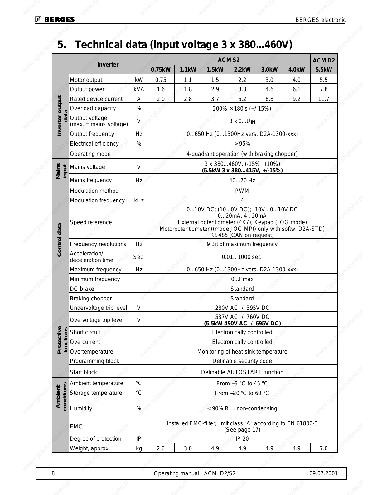
5. Technical data (input voltage 3 x 380...460V)
Inverter ACM S2 ACM D2
0.75kW 1.1kW 1.5kW 2.2kW 3.0kW 4.0kW 5.5kW
Motor output kW 0.75 1.1 1.5 2.2 3.0 4.0 5.5
Output power kVA 1.6 1.8 2.9 3.3 4.6 6.1 7.8
Rated device current A 2.0 2.8 3.7 5.2 6.8 9.2 11.7
Overload capacity % 200% ×180 s (+/-15%)
Output voltage
(max. = mains voltage) V3x0...U
IN
Output frequency Hz 0...650 Hz (0...1300Hz vers. D2A-1300-xxx)
Electrical efficiency % > 95%
Operating mode 4-quadrant operation (with braking chopper)
Mains voltage V 3 x 380...460V, (-15% +10%)
(5.5kW 3 x 380...415V, +/-15%)
Mains frequency Hz 40...70 Hz
Modulation method PWM
Modulation frequency kHz 4
Speed reference
0...10V DC; (10...0V DC); -10V...0...10V DC
0...20mA; 4...20mA
External potentiometer (4K7); Keypad (JOG mode)
Motorpotentiometer ((mode JOG MPt) only with softw. D2A-STD)
RS485 (CAN on request)
Frequency resolutions Hz 9 Bit of maximum frequency
Acceleration/
deceleration time Sec. 0.01...1000 sec.
Maximum frequency Hz 0...650 Hz (0...1300Hz vers. D2A-1300-xxx)
Minimum frequency 0...Fmax
DC brake Standard
Braking chopper Standard
Undervoltage trip level V 280V AC / 395V DC
Overvoltage trip level V 537V AC / 760V DC
(5.5kW 490V AC / 695V DC)
Short circuit Electronically controlled
Overcurrent Electronically controlled
Overtemperature Monitoring of heat sink temperature
Programming block Definable security code
Start block Definable AUTOSTART function
Ambient temperature °C From −5 °C to 45 °C
Storage temperature °C From −20 °C to 60 °C
Humidity % < 90% RH, non-condensing
EMC Installed EMC-filter; limit class "A" according to EN 61800-3
(See page 17)
Degree of protection IP IP 20
Weight, approx. kg 2.6 3.0 4.9 4.9 4.9 4.9 7.0
Inverter output
data
Mains
input
Control dataProtective
functions
Ambient
conditions
BERGES electronic
8 Operating manual ACM D2/S2 09.07.2001
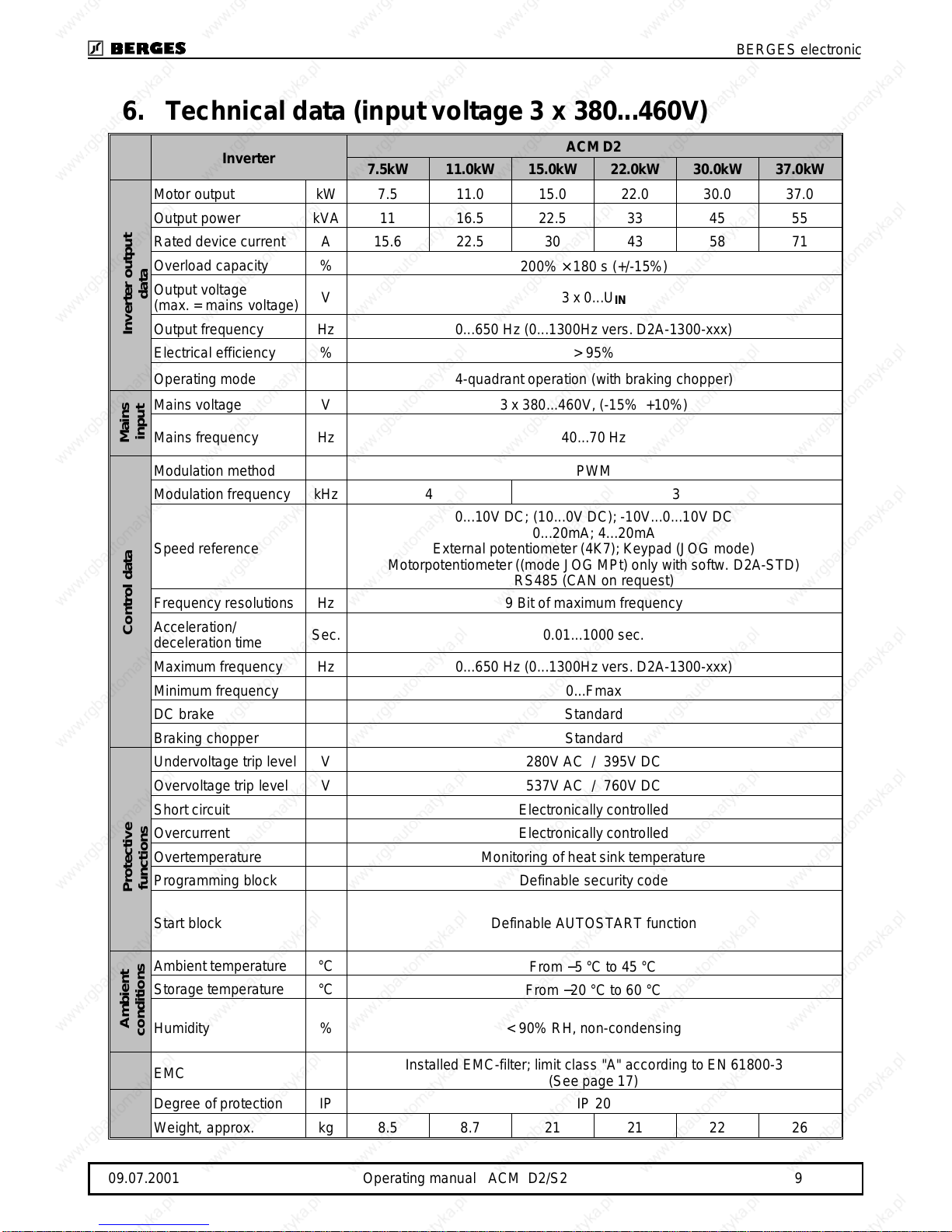
6. Technical data (input voltage 3 x 380...460V)
Inverter ACM D2
7.5kW 11.0kW 15.0kW 22.0kW 30.0kW 37.0kW
Motor output kW 7.5 11.0 15.0 22.0 30.0 37.0
Output power kVA 11 16.5 22.5 33 45 55
Rated device current A 15.6 22.5 30 43 58 71
Overload capacity % 200% ×180 s (+/-15%)
Output voltage
(max. = mains voltage) V3x0...U
IN
Output frequency Hz 0...650 Hz (0...1300Hz vers. D2A-1300-xxx)
Electrical efficiency % > 95%
Operating mode 4-quadrant operation (with braking chopper)
Mains voltage V 3 x 380...460V, (-15% +10%)
Mains frequency Hz 40...70 Hz
Modulation method PWM
Modulation frequency kHz 4 3
Speed reference
0...10V DC; (10...0V DC); -10V...0...10V DC
0...20mA; 4...20mA
External potentiometer (4K7); Keypad (JOG mode)
Motorpotentiometer ((mode JOG MPt) only with softw. D2A-STD)
RS485 (CAN on request)
Frequency resolutions Hz 9 Bit of maximum frequency
Acceleration/
deceleration time Sec. 0.01...1000 sec.
Maximum frequency Hz 0...650 Hz (0...1300Hz vers. D2A-1300-xxx)
Minimum frequency 0...Fmax
DC brake Standard
Braking chopper Standard
Undervoltage trip level V 280V AC / 395V DC
Overvoltage trip level V 537V AC / 760V DC
Short circuit Electronically controlled
Overcurrent Electronically controlled
Overtemperature Monitoring of heat sink temperature
Programming block Definable security code
Start block Definable AUTOSTART function
Ambient temperature °C From −5 °C to 45 °C
Storage temperature °C From −20 °C to 60 °C
Humidity % < 90% RH, non-condensing
EMC Installed EMC-filter; limit class "A" according to EN 61800-3
(See page 17)
Degree of protection IP IP 20
Weight, approx. kg 8.5 8.7 21 21 22 26
Inverter output
data
Mains
input
Control dataProtective
functions
Ambient
conditions
BERGES electronic
09.07.2001 Operating manual ACM D2/S2 9

7.Power-derating in function of the switching
frequency
PNNominal power
POUTOutput power
fPWMSwitching frequency
Ambient conditions: Tamb = 45°C
0,0
0,2
0,4
0,6
0,8
1,0
0481216
f(kHz)
Pout / P N
ACMD2/S2 0,37-2,2kW/230V
ACMS20,75-4,0kW/400V
ACM D2 5,5kW/400V
ACM D2 7,5kW/400V
ACM D2 11kW/400V
ACMD222-37kW/400V
ACMD215kW/400V
N
/ P
out
P
(kHz)
PWM
f
1230
1,2
1,0
0,8
0,6
0,4
0,2
0,06
BERGES electronic
10 Operating manual ACM D2/S2 09.07.2001
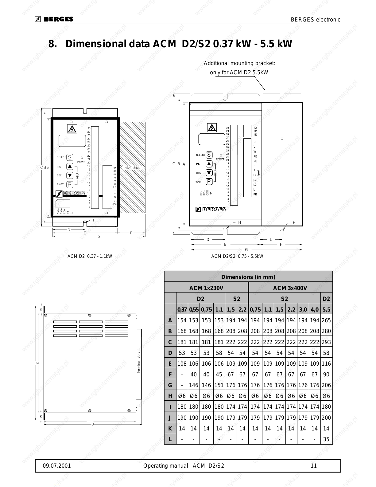
8.Dimensional data ACM D2/S2 0.37 kW - 5.5 kW
Additional mounting bracket:
onlyforACMD25.5kW
Dimensions (in mm)
ACM 1x230V ACM 3x400V
D2S2 S2 D2
0,370,550,751,11,52,20,751,11,52,23,04,05,5
A154153153153194194194194194194194194265
B168168168168208208208208208208208208280
C181181181181222222222222222222222222293
D5353 53 585454 54 545454545458
E108106106106109109109109109109109109116
F-404045676767676767676790
G-146146151176176176176176176176176206
HØ6Ø6Ø6Ø6Ø6Ø6Ø6Ø6Ø6Ø6Ø6Ø6Ø6
I180180180180174174174174174174174174180
J190190190190179179179179179179179179200
K1414 14 141414 14 141414141414
L------------35
ACMD2 0.37 - 1.1kW
C B A
F
G
L
E
D
H
H
ACMD2/S20.75 -5.5kW
BERGES electronic
09.07.2001 Operating manual ACM D2/S2 11

9.Dimensional data ACM D2 7.5 kW- 22.0 kW
Dimensions(inmm)
ACM D2 (3x400V)
7.5 11.015.0 22.0
A317317 330330
B344344 375375
C367367 390390
D54.2554.25 48 48
G209209 250250
HØ7 Ø7Ø6 Ø6
I186186 310310
J198198 325325
K25 2530 30
L154.75 154.75 205205
ACMD27.5 - 11.0kW ACMD2 15.0 - 22.0kW
BERGES electronic
12 Operating manual ACM D2/S2 09.07.2001

10. Dimensional data ACM D2 30.0 kW - 37.0 kW
Dimensions (in mm)
ACM D2 (3x400V)
30.0 37.0
A442 442
B343 408
C422 422
D242 242
E35.5 67
F65.5 98.5
GØ7 Ø7
H255 255
ACM D2 30.0 - 37.0kW
ACM D2 30.0 -37.0kW
BERGES electronic
09.07.2001 Operating manual ACM D2/S2 13
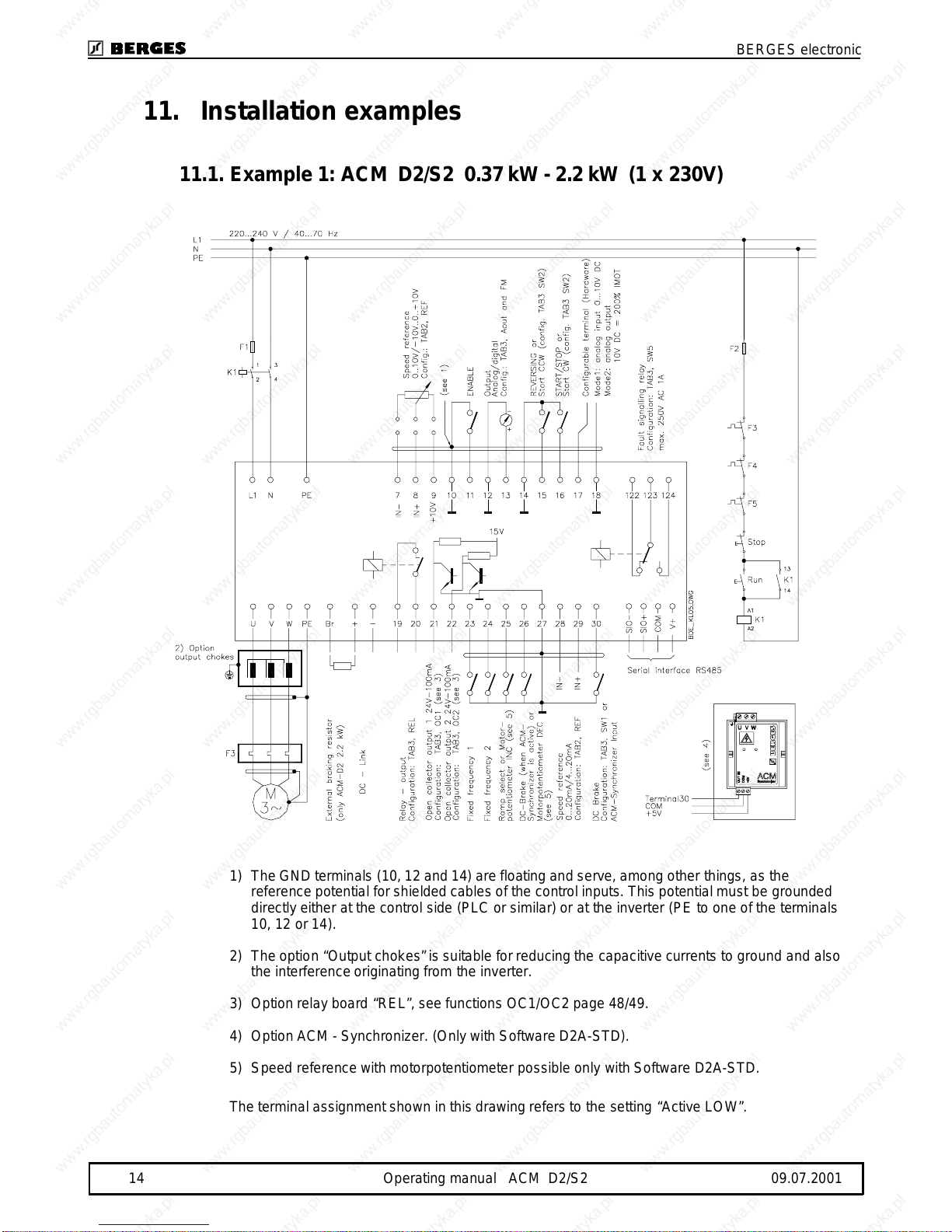
11.Installation examples
11.1.Example1: ACM D2/S20.37kW -2.2kW (1 x 230V)
1)TheGNDterminals (10,12and14)arefloating andserve,amongother things, as the
referencepotentialforshieldedcablesofthe controlinputs. Thispotentialmust be grounded
directlyeither atthe control side(PLC orsimilar)orat the inverter(PEto oneofthe terminals
10, 12 or14).
2)Theoption “Output chokes” issuitable forreducingthecapacitivecurrents to ground and also
the interferenceoriginatingfrom the inverter.
3)Optionrelayboard“REL”,seefunctions OC1/OC2 page48/49.
4)OptionACM-Synchronizer. (OnlywithSoftwareD2A-STD).
5)Speed reference with motorpotentiometerpossibleonlywith SoftwareD2A-STD.
Theterminalassignmentshown inthisdrawingrefersto the setting“Active LOW”.
BERGES electronic
14 Operating manual ACM D2/S2 09.07.2001

11.2.Example2: ACM D2/S20.75kW- 37.0kW (3 x 400V)
1)TheGNDterminals(10,12and14)arefloatingandserve,among other things, as the
referencepotentialforshieldedcablesofthecontrolinputs.Thispotentialmust be grounded
directlyeither at thecontrol side(PLC orsimilar)or at theinverter (PE to oneofthe terminals
10,12or 14).
2)Theoption “Output chokes” issuitablefor reducing thecapacitivecurrents to ground and also
the interference originating fromthe inverter.
3)Optionrelayboard“REL”,seefunctionsOC1/OC2 page48/49.
4)OptionACM-Synchronizer. (OnlywithSoftwareD2A-STD).
5)Speed referencewithmotorpotentiometerpossible onlywithSoftware D2A-STD.
6)Inputsnon-insulated.
Theterminalassignmentshown inthisdrawingrefersto the setting“Active LOW”.
BERGES electronic
09.07.2001 Operating manual ACM D2/S2 15

12.Installation
12.1.Installation
The frequencyinverters aredesigned for installation inaswitchgearcabinet and for
permanentconnection.
The inverter must be installedso that the heat sinkis facing to theright.Onlyin this waysufficient
cooling is guaranteed.
Ifthe inverterhas to beinstalledin adifferent position, externalcooling is required forfull capacity
utilization.
BERGES invertersare generallydesignedsothattheycan be operatedat ambient temperatures
from −5 °C to +45 °C and atarelative humidityof up to 90%.
Formation of condensationmust beavoided!
Please contactBERGES ifthe above values areexceeded. Aheat build-upatthe inverter during
operation mustbe prevented.Theinternal air circulation maypossibly be insufficient if theunit is
installed in a control cabinet with a small volume.
The units should never be installedintheproximityof corrosiveor flammablegases, conductive
dustorlarge magnetic and electric fields.
The inverter should be installed in alocationthat is largely freeofdust,steam and vibrations.
Operationofthe unitsinthepresenceof abrasivedust,steam, condensate, oil mist or aircontaining
saltwillreducetheirusefullife.
Paycloseattentionduringinstallationtoensuringthatnoobjects(such asdrilling swarf,wireor
anythingelse)fallintotheunit.Otherwise adevicefault cannot beexcluded, even after longer
periods of operation.
12.2.Mainspower connection
Toguaranteelastingoperatingsafetyand reliability, the invertermustbeconnected expertly in
accordancewith the valid electricstandards. Attentionmust be paid togoodinsulation from earth
potential onthe power terminals.
Connectasinglephase mainspowersupplywitha ratedvoltagebetween220V and 240V or a
three-phasemainspower supplywith aratedvoltagebetween380Vand 460V (5.5kW 380...415V)
40..70Hztothemainspowerconnectionterminals L1,NorL1,L2,L3and PErespectively(TN-C
System).
L1 (phase)- N 220...240V 40...70Hz PE = earth
L1 L2 L3(phases) 380...460V (5.5 kW 380...415V)40...70Hz PE= earth
Ensureavoltage balance toearth whenfeedinginthe mainspowerthrough an insulating
transformer (star pointearthed)oruse thevector group “DY5”in the case of single-phase inverter
power supply.
BERGES electronic
16 Operating manual ACM D2/S2 09.07.2001
12.3.Motor connection
Connectthe motorcable tothe U, V, W and PE terminals.
The inverter willbedeactivated in theevent of ashort circuitat the terminals U, V, W.
We recommendPTCevaluation using commercially availabledevices toachieveeffective protection
of the motor.
Ifinterruptingcontacts(e.g. contactorsormotorprotectionswitchesetc.) haveto be installedbetween
themotorandinverter,thecircuitmustbeconfiguredsoastoensurethatthe ENABLE signal(terminals
10/11) isdeactivated beforeseparationofthe inverter/motor connection.A relay switching time of
approx. 30ms suffices.
Longmotor cables(>20m) in connection with high voltage peakscausedby thefast switching output
stages oftheinvertermay endangerthe motorinsulation.Insuch cases werecommend tousesuitable
filtermeasures (e.g.motor chokesor dU/dt filters) toprotect themotor.
12.4.Interferencesuppression measures / EMC
(electromagneticcompatibility)
12.4.1.Generalinformation
Invertersare electronic deviceswhich areused in industrialand commercialsystems. In accordance
withthe EMC-directives89/336/EECthe invertersarenotdesignedfor independentoperation.Thus
invertersshould beusedforfurtherprocessingthroughcompetent machine/systemmanufacturers.
Bythis,the devices donot require a CE-marking. Theproofofthe conformityofthe machine/system
with the required EMC-directives must be furnished by themanufacturer or operator ofthesystem.
The invertersofthe ACM series areequipped withan internal filter and designed to be used in class
"A"environments(firstenvironment,restricteddistribution)accordingtotheproduct standard EN
61800-3.
The evaluationofthe conformitytook place inapracticalstructurehavingtaken into accountthe
following installationnotes.
Voltage peaks producedbyotherdevicesconnected atthemains supplycan possibly disturb or even
damage the inverter.Inputchokes(option)can be usedtoprotect the inverteragainst these voltage
peaks (causede.g.byswitching offof highloadsfrom themains).
12.4.2.Installation notes
Duringoperation, electrical/electronicdevices caninfluence ordisturbeachother via powersupply or
othermetallic connections.
The electromagnetic compatibilityof thesystemis highly influenced bythe manner of the installation.
Measuresforthegrounding,shieldingand filteringaretobeparticularlyconsidered. Bypayingattention
tothefollowinginstallationnotesitcan beassumed that the EMC limit values for thesystem/machine
are kept.
•Invertersand optional components likeinput oroutputchokes mustbe inmetal-to-metal contact
withthegrounded mounting plateusing the wholesurface ifpossible. Usepreferablygalvanized
mounting plates. Painted mounting surfacesmustbe free from paint.
•Laythemains, motor andcontrol cablesin large distance from each other.
•Useshieldedmotorcablesconnectedtoearth onboth sides.
•Connect themotor cable shieldwiththePE terminallocatedinthe terminalbox ofthe motor. Use
possibly metalliccableglands.
•Optionaloutputchokesmust bemounted closeto the inverterand connectedwith shielded cables.
Connect thecableshield toearth on both sides.
•Useshieldedcontrol cablesconnectedtoearth on both sides.
•Unshielded control cables must be twisted.
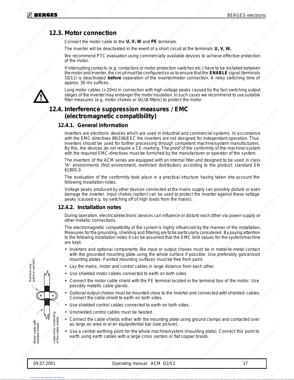
•Connectthecableshieldseitherwith themounting plate using groundclampsandcontacted over
as large an area oratan equipotential bar(see picture).
•Useacentral earthing point for thewholemachine/system (mounting plate).Connect this pointto
earth usingearth cables witha large crosssection or flat copperbraids.
Remove any
paint or varnish!
Motor cable with
braided shield.
Large-area contacting
of the cable shield.
BERGES electronic
09.07.2001 Operating manual ACM D2/S2 17

•Do not extend the shields with single wiresand do notinterrupt themif possible.
•Whenconstructingthe switchgearcabinetorthesystem,separatethepower sectionfrom the
controlsection. Eventuallyprovide a shieldbetween power and control section.
•Wireinductiveswitchingelements (coilsof contactorsorrelays)withRC-elements,free-wheeling
diodes or varistors.
12.5.Mainsback-up fuses
External upstream fusesare requiredtoprotectthecablesandthe unititself. Thefuses mustbe
dimensionedso asto permitstarting up andnormaloperationofmotors.To guarantee this,we
recommendthe useofthe followingsslow-blow fuses:
Mains input 1 x 230V
0.37kW0.55kW0.75kW 1.1kW2.2kW
4A 8A 8A 8A 16A
Mains input 3 x 400V
0.75kW 1.1kW 1.5kW2.2kW3.0kW 4.0kW5.5kW
4A6A 6A 8A 10A 16A 20A
Mains input 3 x 400V
7.5kW 11.0kW 15.0kW 22.0kW 30.0kW 37.0kW
35A 35A 63A 63A 80A100A
12.6.Ventilation
Forall inverters,thepermissibleambient temperatureof 45°Cmustnotbeexceeded. This
particularly appliesifthe inverter isinstalledin acontrol cabinet,because operationoftheinverter
mayincreasethe ambienttemperature substantially.Appropriatemeasures, e.g.installationofa
fan,mustbe taken if thepermissibleambienttemperature isalmost reached or exceeded under
full loading of theinverter.
BERGES electronic
18 Operating manual ACM D2/S2 09.07.2001
Other manuals for ACM-D2 Series
1
This manual suits for next models
1
Table of contents
Other Berges Inverter manuals


