OmarLift SIEMENS SINAMICS V20 User manual

Siemens V20_EN_rev01-08032019.docx 0-0
0
INVERTER SIEMENS V20

Siemens V20_EN_rev01-08032019.docx 0-1
Sommario
0................................................................................................................................................................ 0-0
1INTRODUCTION....................................................................................................................................1-1
2SAFETY INSTRUCTIONS AND PRECAUTIONS..................................................................................2-1
2.1 SAFETY INSTRUCTIONS..............................................................................................................2-1
2.2 PRECAUTIONS..............................................................................................................................2-1
3POWER MODULE.................................................................................................................................. 3-1
3.1 POWER MODULE V20 ..................................................................................................................3-1
3.1.1 Description.............................................................................................................................. 3-1
3.1.2 Warnings.................................................................................................................................3-1
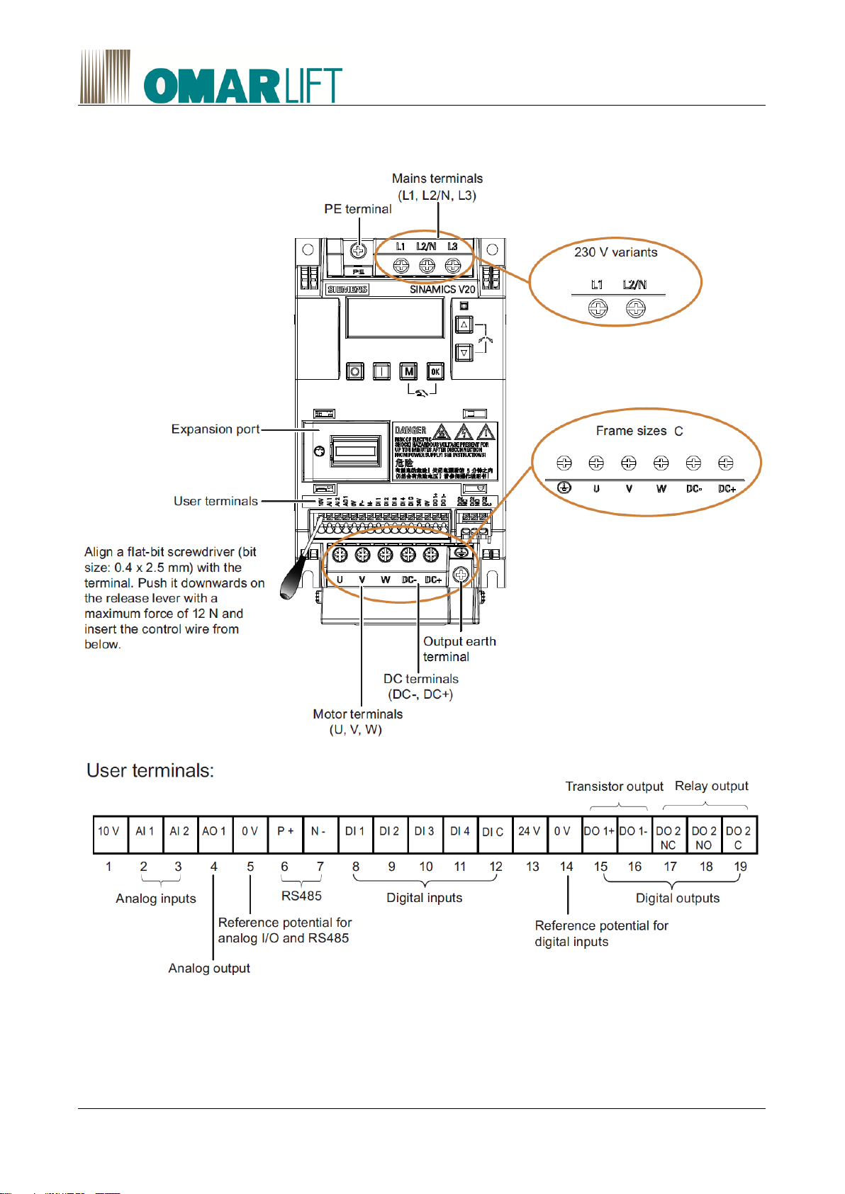
3.1.3 Terminal description ............................................................................................................... 3-2
3.1.4 Dimension drawings ............................................................................................................... 3-3
3.1.5 Wiring......................................................................................................................................3-4
3.1.6 Technical data......................................................................................................................... 3-5
4EMC-COMPLIANT INSTALLATION (EMC) ........................................................................................... 4-6
5BRAKING RESISTORS.......................................................................................................................... 5-8
6CONTROL UNIT.....................................................................................................................................6-1
6.1 DESCRIPTION ............................................................................................................................... 6-1
6.2 SAFETY WARNING ....................................................................................................................... 6-1
6.3 USER TERMINALS........................................................................................................................6-1
6.4 TECHNICAL DATA.........................................................................................................................6-1
7POWER WIRING.................................................................................................................................... 7-3
7.1 POWER CIRCUIT CONNECTION .................................................................................................7-3
7.2 SAFETY INSTRUCTIONS..............................................................................................................7-3
7.3 RULES FOR EMC COMPLIANT MOTOR - INVERTER WIRING..................................................7-3
7.4 SIEMENS V20 ELECTRICAL WIRING ..........................................................................................7-5
8PROGRAMMING THROUGH PC ..........................................................................................................8-1
9PROGRAMMING THROUGH KEYBOARD AND MENU....................................................................... 9-1
9.1 EXPANSION PORT (Optional)....................................................................................................... 9-1
9.2 THE BUILT-IN BASIC OPERATOR PANEL (BOP) .......................................................................9-1
9.2.1 Inverter menu.......................................................................................................................... 9-3
9.2.2 Viewing inverter status............................................................................................................9-4
9.2.3 Editing of parameters..............................................................................................................9-4
9.2.4 Screen displays.......................................................................................................................9-5
9.2.5 LED warnings..........................................................................................................................9-6
9.3 QUICK COMMISSIONING .............................................................................................................9-6
9.3.1 Quick commissioning through the Setup menu...................................................................... 9-6
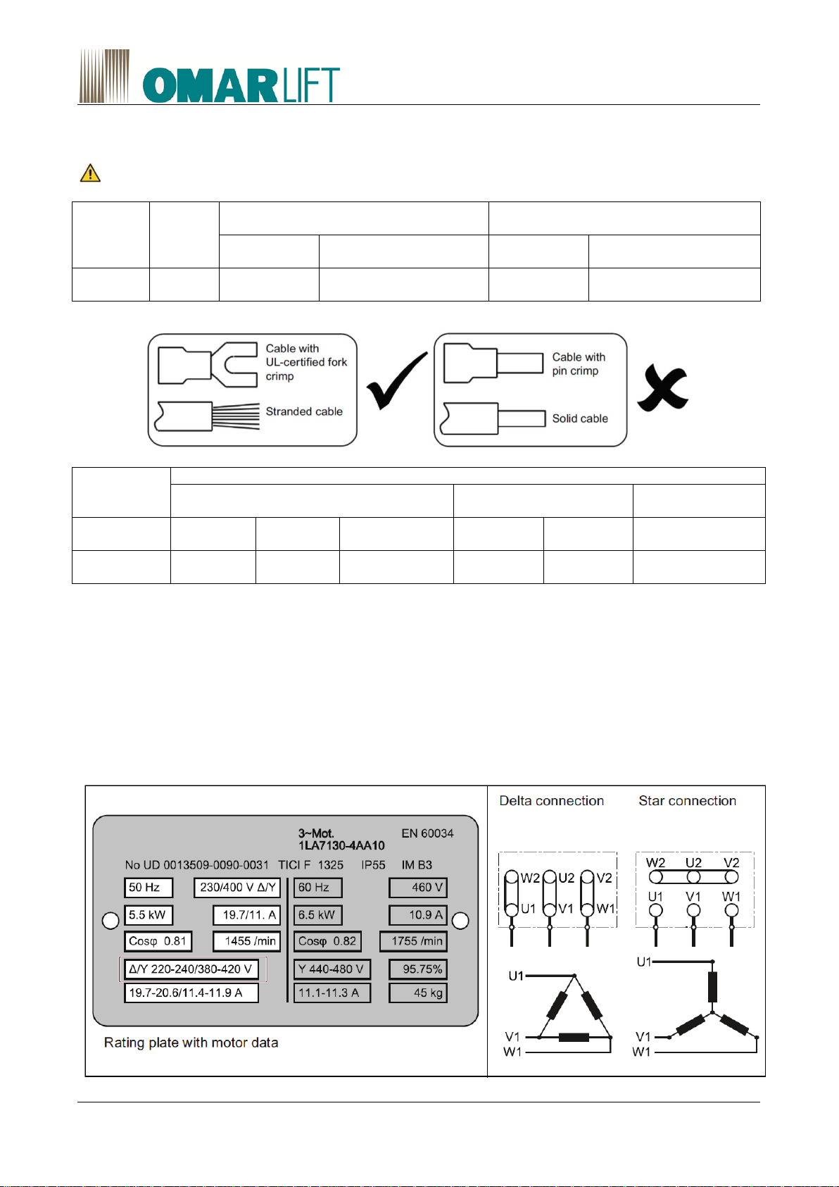
9.3.2 Setting motor data .................................................................................................................. 9-7
9.3.3 Setting connection-macros.....................................................................................................9-8
9.3.4 Setting application macros...................................................................................................... 9-8
10 PARAMETERS.................................................................................................................................10-9

Siemens V20_EN_rev01-08032019.docx 0-2
10.1 DISPLAY PARAMETERS.............................................................................................................10-9
10.2 INVERTER COMMISSIONING.....................................................................................................10-9
10.3 PARAMETER LIST.......................................................................................................................10-9
10.4 CONFIGURATION PARAMETERS.............................................................................................. 10-9
10.4.1 Upwards................................................................................................................................10-9
10.4.2 Power limitation...................................................................................................................10-10
10.4.3 Downward........................................................................................................................... 10-11
10.5 RUPTURE VALVE TEST............................................................................................................10-11
11 ACTIVE FAULTS & ALERT............................................................................................................ 11-11
11.1 FAULT CODES...........................................................................................................................11-12
11.2 ALERT CODES .......................................................................................................................... 11-13
12 CHECKS AND MAINTENANCE.......................................................................................................12-1
12.1 MEGGER TEST............................................................................................................................12-1

Siemens V20_EN_rev01-08032019.docx 1-1
1 INTRODUCTION
SIEMENS V20 is an inverter with a specialized software in hydraulic systems, which controls only the up-
ward travel.
These inverters SIEMENS can be applied to both pump units of the old generation, and pump units most re-
cent and modern.
The advantages are:
Absence of starting current peaks. The maximum starting current is the rated current In.
Power factor correction. Cosϕ≥0.98.
Power saving.
Comfort optimization.
Setting parameters of high/low speed.
Maximum power absorbed from the network adjustable, to reduce the power costs.
Absence of braking resistors.
For further information regarding the functions of the inverter Siemens V20, refer to the relevant manu-
als on the website.
All information, manuals and details, can be found at the internet address:
http://support.automation.siemens.com
.

Siemens V20_EN_rev01-08032019.docx 2-1
2 SAFETY INSTRUCTIONS AND PRECAUTIONS
Read all of this manual before powering the equipment, following step by step the procedures.
2.1 SAFETY INSTRUCTIONS
Carefully follow the procedures given below, to prevent the risk of serious accidents.
1- The leakage current from the inverter to earth is greater than 30mA, therefore a differential
switch with Id of at least 300mA, type B or type A, must be provided. Regulations require the use
of a cable with a section of at least 10 mm² for the earth connection. If the differential switch trips
when the main power switch is closed, do not repeat the operation in succession, because
the inverter could become permanently damaged.
2- If the parameters are incorrect, the inverter can cause the motor to rotate at a speed higher than
synchronous speed. Do not run the motor beyond its electrical and mechanical limits. The installer is
responsible for ensuring that movements occur in safe conditions, without exceeding the specified
operating limits.
3- Risk of electrocution. Power on the inverter only with the front cover fitted. NEVER remove the cover
during operation. Before carrying out any operation on the equipment, disconnect the power supply
and wait a few minutes for the internal capacitors to discharge.
4- The inverter must always be connected to the mains. In case of an interruption, wait at least 1 mi-
nute before reconnecting. RECONNECTING WITHOUT WAITING LONG ENOUGH WILL DAMAGE
THE INVERTER.
5- Do not use an oscilloscope or similar instruments to test the internal circuits of the inverter. This type
of operation must be performed only by specialized personnel.
2.2 PRECAUTIONS
Carefully follow the procedures given in the manual to avoid the risk of damaging the inverter.
1- Do not connect the equipment to a voltage higher than that permissible. An excessive voltage can
cause permanent damage to the internal components.
2- To avoid damaging the inverter in case of prolonged stoppages with no power supply, before
restarting proceed as follows:
- If the inverter has been idle for several months, connect it to the power supply for at least 1
hour in order to regenerate the bus capacitors.
- If the inverter has been idle for more than one year, power it for 1 hour at 50% less than the
nominal voltage, and then for 1 hour at nominal voltage.
3- Do not connect capacitors to the inverter outputs.
4- Before resetting an inverter fault, carefully check what caused activation of the protection.
5- Use an inverter with rated current equal to or higher than the motor rated current.

Siemens V20_EN_rev01-08032019.docx 3-1
3 POWER MODULE
3.1 POWER MODULE V20
3.1.1 Description
SINAMICS V20 is a family of inverters developed to control the speed of asincronous motors.
The inverters are available in many frame sizes.
Component
Rated
output
power
Rated in-
put current
Rated out-
put num-
ber
Order number
Filtered
Frame size C
(with single fan)
2,2 kW
27,2 A
11 A
6SL3210-5BB22-2AV0
3,0 kW
32 A
13,6 A
6SL3210-5BB23-0AV0
3.1.2 Warnings
Mounting clearance
Top
≥ 100 mm
Bottom
≥ 100 mm
Side
≥ 0 mm
ATTENTION:
Always mount the inverter vertically oriented!

Siemens V20_EN_rev01-08032019.docx 3-2
3.1.3 Terminal description
Terminal layout

Siemens V20_EN_rev01-08032019.docx 3-3
3.1.4 Dimension drawings
Frame size C

Siemens V20_EN_rev01-08032019.docx 3-4
3.1.5 Wiring
3.1.5.1 Cables
WARNING: Contact with live parts can result in death or serious physical injury
Frame
size
Rated
output
power
Mains and PE terminals
Motor / DC / braking resistor / output
earth terminals
Cable cross-
section
Screw tightening torque
(tolerance: ± 10%)
Cable cross-
section
Screw tightening torque
(tolerance: ± 10%)
C
2,2 –
3,0 kW
10 mm2
2,4 Nm
4,0 mm2
2,4 Nm
Inverter va-
riant
Maximum cable length
Without output reactor or external EMC
filter
With output reactor
With external
EMC filter
230 V
Unshielded
Shielded
EMC compliant
(RE/CE C2) 1)
Unshielded
Shielded
EMC compliant
(RE/CE C2) 2)
Da FSB a
FSC
50 m
25 m
25 m
200 m
200 m
5 m
1) For filtered variants only. RE/CE C2 refers to EMC compliance to EN61800-3 Category C2 for Radiated
and Conducted Emissions.
2) For unfiltered variants only.
3.1.5.2 Star-delta connection of the motor
V20 single-phase inverter requests a 1AC 230V connection in input.
The output connection is 230V 3AC and is must be carried out consistently with the motor connection, con-
sidering that the supply voltage will never exceed the input voltage
For instance, select delta connection if either a 230 / 400 V motor on a 400 V inverter or a 120 / 230 V motor
on a 230 V inverter is supposed to operate at 87 Hz instead of 50 Hz.

Siemens V20_EN_rev01-08032019.docx 3-5
3.1.6 Technical data
V20 with filter
6SL3210
5BB23-0AV0
Input current
Voltage
Frequency
Rated current
V
Hz
A
200 ÷ 240V 1AC
47 ÷ 63
32
Output current
Rated current In
Peak current Imax
Overload MAX
A
A
3AC
13,6
20,4
150% In x 60s + 24,5% In x 240s
Rated pulse frequency
kHz
4
Power loss
kW
0,114
24 VDC supply
A
≤50 mA
Fuses
Rated current
3NA 3820
50A
Connectors
Line supply L1, L2, L3
Motor connection U2, V2, W2
By screw
Tightening torque
2,4 Nm (±10%)
Degree of protection
IP20
Room temperature
Moisture
0°C ÷ 40°C without derating
0 ÷ 95% without condensation
Weight
kg
3,2

Siemens V20_EN_rev01-08032019.docx 4-6
4 EMC-COMPLIANT INSTALLATION (EMC)
Together with a system configuration in conformity with EMC standards (see norms EN 61000-6-2,
EN61000-6-4, EN60204-1), the line filters limit the conducted interference emitted by the Power Modules to
limit values according to standard EN61800-3.
For PM this is obtained by mains integrals filters.
The PM with a suitable line filter shall correspond to the category C2 for domestic installations, provided that:
1. they are installed and put into service by a specialist (according to the definition given by the norma-
tive), in compliance with the limit values for electromagnetic compatibility
2. the below shown additional requisites are respected:
Connection by use of a shielded cable at reduced capacity
Motor cable shorter than 25 m
Pulse frequency ≤ 4 kHz
Current ≤ nominal input current in the technical data
The shield connection kit allows easy and efficient connection of the necessary shield to achieve EMC-
compliant installation of the inverter. If no shield connection kit is used, you can alternatively mount the de-
vice and additional components on a metal mounting plate with excellent electrical conductivity and a large
contact area. This mounting plate must be connected to the cabinet panel and the PE or EMC bus bar.
The following diagram shows an example of EMC-compliant installation of the inverter frame size C.
Shielding method
The following illustration shows an example with and without the shielding plate.
EMC-compliant cabinet design

Siemens V20_EN_rev01-08032019.docx 4-7
The most cost-effective method of implementing interference suppression measures within the control cabi-
net is to ensure that interference sources and potentially susceptible equipment are installed separately from
each other.
The control cabinet has to be divided into EMC zones and the devices within the control cabinet have to be
assigned to these zones following the rules below.
The different zones must be electromagnetically decoupled by using separate metallic housings or
grounded separation plates.
If necessary, filters and/or coupling modules should be used at the interfaces of the zones.
Cables connecting different zones must be separated and must not be routed within the same cable
harness or cable channel.
All communication (e.g. RS485) and signal cables leaving the cabinet must be shielded.

Siemens V20_EN_rev01-08032019.docx 5-8
5 BRAKING RESISTORS
The inverter handle only the upward travel in consequence of that, there are not cur-
rents generated and MUST NOT BE INSTALLED ANY BRAKING RESISTOR.
The downward direction is regulated by hydraulic valve. To adjust downward parameters, refer to the manual
of the installed valve.

Siemens V20_EN_rev01-08032019.docx 6-1
6 CONTROL UNIT
6.1 DESCRIPTION
The logical Control unit and adjustment is integrated in the power unit of the machine
6.2 SAFETY WARNING
WARNING
Danger fire in case of overheating in case of insufficient free ventilation spaces:
Absolutely observe a 50 mm clearance up and down the Control Unit and the Control Unit Adapter
Be sure that the ventilation openings are not blocked by connecting cables.
WARNING
Incorrect parameterization can result in machine malfunctions and consequently the risk of death and injury
6.3 USER TERMINALS
There are 19 terminals available through which the input / output connections can be made:
6.4 TECHNICAL DATA
Following there are the technical data related to the user interface terminals:
No
Terminal
marking
Description
1
10V
10V output (tolerance ± 5 %) referred to 0V, maximum 11 mA, short cir-
cuit protected
Analog
inputs
2
3
Al1
Al2
Mode:
AI1: Single-ended, bipolar current and
voltage mode
AI2: Single-ended, unipolar current
and voltage mode
Isolation to control circuit:
None
Voltage range:
AI1: -10 - +10V; AI2: 0 - 10V
Current range:
0 - 20 mA (4 to 20 mA - software se-
lectable)
Voltage mode accuracy:
± 5% full scale
Current mode accuracy:
± 5% full scale
Input impedance:
Voltage mode: > 30 K
Current mode: 235 R
Resolution:
10-bit
Wire break detect:
Yes
Threshold 0 ⇒1 (used as DIN):
4,0V
Threshold 1 ⇒0 (used as DIN):
1,6V
Response time (digital input
mode):
4 ms ± 4 ms
Analog
4
A01
Mode:
Single-ended, unipolar current mode
Isolation to control circuit:
None

Siemens V20_EN_rev01-08032019.docx 6-2
output
Current range:
0 to 20 mA (4 to 20 mA - software se-
lectable)
Accuracy (0 to 20 mA):
± 1 mA
Output capability:
20 mA into 500 R
5
0V
Overall reference potential for RS485 communication and analog inputs /
output
6
P+
RS485 P +
7
N-
RS485 N -
Digital
inputs
8
9
10
11
12
DI1
DI2
DI3
DI4
DI C
Mode:
PNP (reference terminal low)
NPN (reference terminal high)
Characteristics values are inverted for
NPN mode.
Isolation to control circuit:
500 V DC (functional low voltage)
Absolute maximum voltage:
± 35 V for 500 ms every 50 seconds
Operating voltage:
- 3 V to 30 V
Threshold 0 ⇒1 (maximum):
11 V
Threshold 1 ⇒0 (minimum):
5 V
Input current (guaranteed off):
0,6 to 2 mA
Input current (maximum on):
15 mA
2-wire Bero compatibility:
No
Response time:
4 ms ± 4 ms
Pulse train input:
No
13
24V
24 V output (tolerance: - 15 % to + 20 %) referred to 0 V, maximum 50
mA, non-isolated
14
0V
Overall reference potential for digital inputs
Digital
output
(transistor)
15
16
DO1 +
DO1 -
Mode:
Normally open voltage-free terminals,
polarised
Isolation to control circuit:
500 V DC (functional low voltage)
Maximum voltage across
terminals:
± 35 V
Maximum load current:
100 mA
Response time:
4 ms ± 4 ms
Digital
output
(relay)
17
18
19
DO2 NC
DO2 NO
DO2 C
Mode:
Change-over voltage-free terminals,
unploarised
Isolation to control circuit:
4 kV (230 V mains)
Maximum voltage across termi-
nals:
240 V AC / 30 V DC + 10%
Maximum load current:
0,5 A @ 250 V AC, resistive
0,5 A @ 30 V DC, resistive
Response time:
Open: 7 ms ± 7 ms
Close: 10 ms ± 9 ms
WARNING
Risk of electric shock
The input and output terminals, numbered 1 to 16, are safety extra low voltage (SELV)
terminals and must only be connected to low voltage supplies.

Siemens V20_EN_rev01-08032019.docx 7-3
7 POWER WIRING
7.1 POWER CIRCUIT CONNECTION
All electrical wirings have to be done, respecting the rules shown in the table below:
L1; L1
Mains power supply input
Connect the mains power supply input phases in any order.
U; V; W
Inverter output
Connect the three output phases to the contactors, then to the
motor.
PE
Earth (protection)
Connect to the building's earth system.
7.2 SAFETY INSTRUCTIONS
1- Do not power the inverter without first making the earth connection.
2- To increase inverter protection (especially against overvoltage due to electrical storms), three extra-
fast-blow fuses (one for each phase) can be installed in series with the supply mains input terminals.
The fuses must be rated according to the various sizes. The set of fuses, complete with protection
box, can be supplied on request (not indispensable!).
3- To avoid permanently damaging the inverter, do not connect braking resistors with resistance or
power ratings lower than those given in the table.
4- The inverter drive must be connected “upstream” of the power contactors.
5- Wire earth connections and masses correctly to avoid problems of EMC interference.
6- Pay particular attention to the power connection; if the input and output are inverted, the in-
verter will inevitably be damaged.
7.3 RULES FOR EMC COMPLIANT MOTOR - INVERTER WIRING
For a correct wiring of the group INVERTER - ENGINE, in addition to the procedure described in Chapter 4,
about electromagnetic compatibility, follow the steps below:
1- The inverter and motor must be connected directly to the building's earth system.
2- The power cables for the inverter/contactors and contactors/motor connection must be as short as
possible, shielded four-core (three phases plus yellow/green earth wire), or four unshielded cables
bound together and inserted in a raceway or a metal pipe connected to earth. In other words, there
must be an earth wire as close as possible to the power wires in the same cable or in the same pipe.
If shielded cable is used, continuity of the earth braid between the inverter/contactors and contac-
tors/motor section must be ensured.
It is advisable to connect the shielding to earth at both ends by means of a U-clip or with special ter-
minals.
If the shield cannot be connected with a U clip inside the motor terminal block, it must be earthed on
the frame before entering the terminal block.
3- Even if it is not essential, a good engineering way provides to have a shielded cable also in the pow-
er line in input, in order to prevent that irradiated noises are brought out, by means this cable.
4- The inverter power cables (input and output) and control cables must be kept as far apart as possi-
ble and must not run parallel, even if shielded; if the cables cross, they must be arranged at an angle
of 90°.
5- Irrespective of the connection to the building's earth system, the motor frame MUST be connected to
the cable shield and to the yellow/green earth wire inside the shielded cable.
6- The inverter emits radiated interference, which can therefore be picked up and carried outside the
panel by the cables, especially by flexible cables which radiate the interference into the lift shaft. If
this problem is to be avoided, the connections between the panel and the inverter must be made us-
ing shielded wires with shield connected to earth at both ends. Shielded cables must not be used

Siemens V20_EN_rev01-08032019.docx 7-4
without the shield connected to earth, as in this case any interference will be greater than with an
unshielded cable.
Any free or unused wires in a multicore cable must be connected to earth at both ends.
7- Any cable, for control or external connections for the shaft and lift car, must never run near and par-
allel to the power cable, even if shielded; if parallel routing cannot be avoided, they must be in sepa-
rate metal raceways.
8- All earth connections must be as short and wide as possible.
9- To avoid unwanted tripping of the differential switch:
Make the power connection as short as possible
Use suitable differential switches (type A or B 300mA)
When possible, reduce the inverter carrier frequency: in fact, as lower is the frequency, is
greater the motor noise, but with less current leakage to earth and less EMC interference; so
the motor windings are less stressed.

Siemens V20_EN_rev01-08032019.docx 7-5
7.4 SIEMENS V20 ELECTRICAL WIRING
Permissible I/O terminal cable cross-sections
Cable type Permissible cable cross-section
Solid or stranded cable 0.5 to 1.5 mm2
Ferrule with insulating sleeve 0.5 mm2
*1 Use shielded screw for analog inputs.
*2 Only with optional power limitation function.
230V 3AC
TO CONTACTORS

Siemens V20_EN_rev01-08032019.docx 9-1
8 PROGRAMMING THROUGH PC
For the SIEMENS V20 inverter, is not available an interface tool for parameters programming directly via PC;
therefore it is necessary to proceed in case of parameters values modification by using the keypad and the
screen supplied on the front of the inverter (BOP).
9 PROGRAMMING THROUGH KEYBOARD AND MENU
9.1 EXPANSION PORT (Optional)
The expansion port (optional) is designed for connecting the inverter to the external option module
- BOP Interface Module or Parameter Loader, in order to realize the following functions:
Operating the inverter from the external BOP
Cloning parameters between the inverter and a standard MMC / SD card
Powering the inverter from the Parameter Loader, when mains power is not available.
9.2 THE BUILT-IN BASIC OPERATOR PANEL (BOP)
The Basic Operator Panel BOP is an operator panel with six keys and a backlight display unit. The BOP is
inserted on the Inverter V20.
The BOP supports the following functions:
Input of parameters and activation of functions
Display of operating modes, parameters, alarms and faults
WARNING: DON’T USE THE BUTTONS 0/1.
The buttons 0/1 bypass the panel signals, so the starting and the stopping of the inverter and the motor
are under exclusive control and responsibility who activate them.
Funzioni pulsante
O
(STOP)
Stops the inverter
Single press
OFF1 stop reaction: the inverter brings the motor to a
standstill in the ramp-down time set in parameter P1121.

Siemens V20_EN_rev01-08032019.docx 9-2
Note:
If configured to be an OFF1 stop, this button is inactive in
AUTO mode.
Double press (< 2 s) or
long press ( > 3 s)
OFF2 stop reaction: the inverter allows the motor to coast
to a standstill without using any ramp-down times.
I
(RUN)
Starts the inverter
If the inverter is started in HAND / JOG mode, the inverter running icon ( ) displays.
Note:
This button is inactive if the inverter is configured for control from terminals (P0700 = 2,
P1000 = 2) and is in AUTO mode.
M
Multi-function button
Short press ( < 2 s)
Enters the parameter setting menu or moves to the
next screen
Restarts the digit by digit editing on the selected item
If pressed twice in digit by digit editing, returns to the
previous screen without changing the item being edit-
ed
Long press ( > 2 s)
Returns to the status screen
Enters the setup menu
OK
Short press ( < 2 s)
Switches between status values
Enters edit value mode or change to the next digit
Clears faults
Long press ( > 2 s)
Quick parameter number or value edit
M+OK
Hand / Jog / Auto
Press to switch between different modes:
Note:
Jog mode is only available if the motor is stopped and it is a mode of operation of low-
speed service.
▲
When navigating through a menu, it moves the selection up through the screens
available.
When editing a parameter value, it increases the displayed value.
When the inverter is in RUN mode, it increases the speed.
Long press (> 2 s) of the key quickly scrolls up through parameter numbers, indices,
or values.
▼
When navigating through a menu, it moves the selection down through the screens
available.
When editing a parameter value, it decreases the displayed value.
When the inverter is in RUN mode, it decreases the speed.
Long press (> 2 s) of the key quickly scrolls down through parameter numbers, indi-
ces, or values.
▲+▼
Reverses the direction of rotation of the motor. Pressing the two keys once activates re-
verse motor rotation. Pressing the two keys once again deactivates reverse rotation of
the motor. The reserve icon ( ) on the display indicates that the output speed is oppo-
site to the setpoint.
Table of contents