BERMAD FP 400E Owner's manual
BERMAD Fire Protection
400 Series
FP 400E Deluge Valve Data
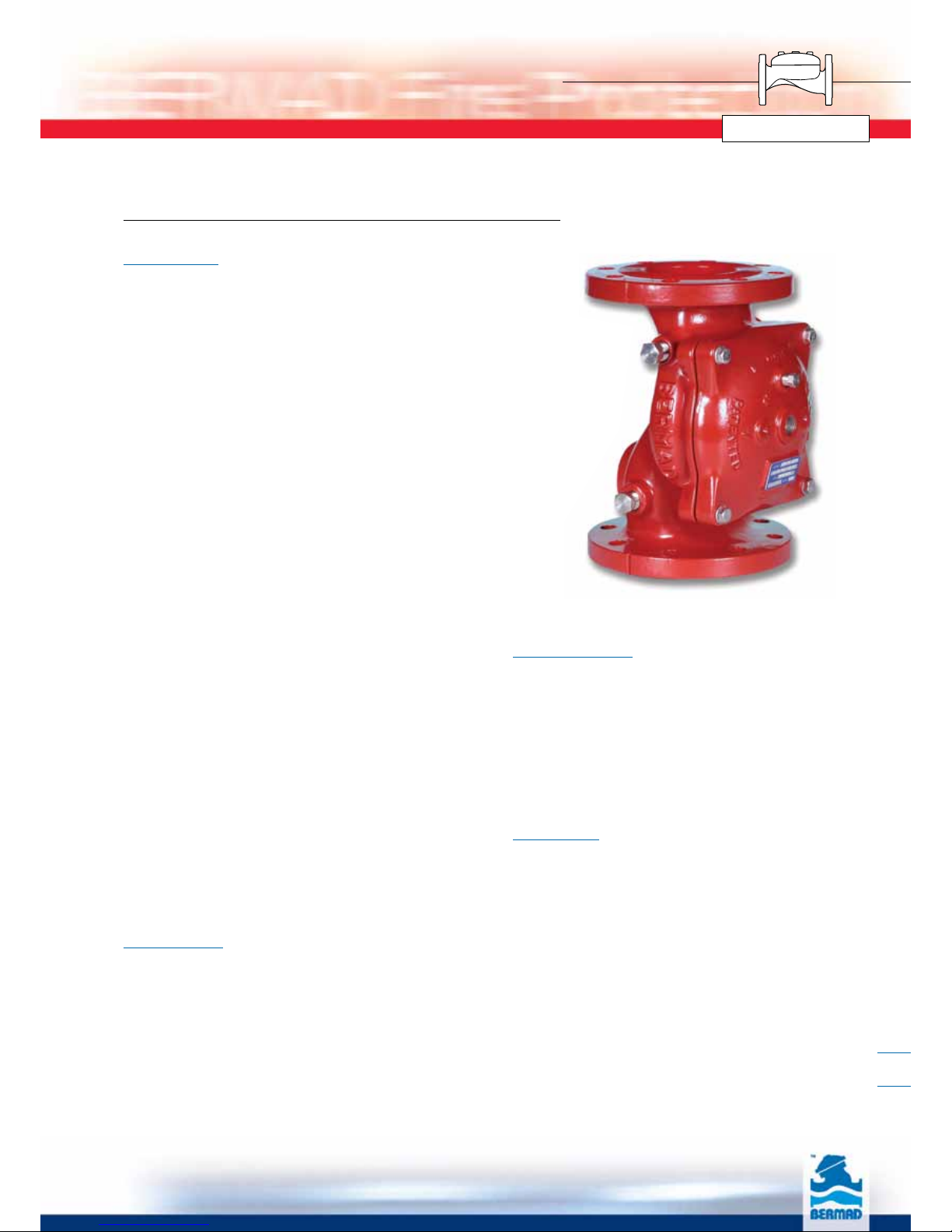
Description
BERMAD FP 400E Deluge Valves are elastomeric- type
globe valves that are rolling-diaphragm actuated, with an
integral, solid, resilient seal. These automatic water
control valves are designed for vertical or horizontal
installation and are available in diameter sizes from 1½” to
14” (DN40 to DN350).
The BERMAD FP 400E valves are used for water flow
control in Deluge, Combination Pressure Control Deluge,
Preaction or Water/Foam systems, and are manufactured
from various materials and coatings to suit all kind of
industrial specifications.
The FP 400E Deluge Valve is held closed by system water
pressure trapped in the control chamber. When the
releasing system operates, pressure is released from the
control chamber, and the seal disc opens to allow water
to flow into the system.
The design of the FP 400E valve body includes a single,
full bore seat with unobstructed flow path, free of any
in-line ribs, supporting cage, or shafts.
The unique hydro-dynamic globe design provides high
flow capabilities with minimum head loss. The cover is
removable via four (4) fastening bolts (up to 10”) for quick
in-line inspection and servicing.
The internal design of the FP 400E valve is based on
innovative technology using advanced rubber-based
materials to achieve a solid, one-piece, elastomeric
assembly including flexible fiber reinforced diaphragm,
vulcanized with a rugged radial seal disk, and together
providing resilient, drip-tight sealing. The elastomeric
assembly is carefully balanced and peripherally supported
to avoid tension and protect the elastomer, resulting in
long-life, controlled actuation, even under harsh
conditions.
The elastomeric assembly can be easily removed from the
valve body with no need for disassembling the valve from
the line.
Accessories
The BERMAD FP 400E Deluge Valve are trimmed with
the original components and accessories per
specification and in accordance with valve functions and
applications.
Where additional specifications and/or signaling devices
are required for a specific application, refer to system
data for the system used, and to the BERMAD data
sheet and Installation, Operation & Maintenance for
specific model required.
Main Features
■One-piece molded elastomeric moving part –
No maintenance required
■In-line serviceable, field replaceable internal parts
■Obstacle free, full bore
■Available in corrosion resistant materials
■Designed to be reset without opening the valve
■Compatible with electric/hydraulic/pneumatic release
and pressure control trim systems
Approvals
■UL Listed to UL 260 from 5 to 250 psi (0.3 to 17.2 bar)
Working Pressure, 1-½” through 10”
(DN40 through DN250)
■ABS Approved for 300 psi (21 bar) maximum working
pressure, 1-½” through 14” (DN40 through DN350)
■Lloyd’s Register Type Approval for 300 psi (21 bar)
maximum working pressure, 1-½” through 14”
(DN40 through DN350)
■Fire Test Certified to ISO 6182 part 5, 1-½”
through 12” (DN40 through DN300)
Notes:
1. The FP 400E valve shall be trimmed with specific
components & accessories.
2. The FP 400E valve must be installed and maintained in
compliance with the most recent BERMAD publications.
1

BERMAD Fire Protection
400 Series
FP 400E Materials Specifications
Construction Materials
The BERMAD FP 400E valves are available in a variety of materials to
ensure optimal suitability for a wide range of applications. When the
valve is designed for external corrosive environments and/or internal
corrosive fluid, an adequate Body and Cover resistant material shall be
used.
It is recommended to apply the “High Build Epoxy Fusion-Bonded with
UV Protection, Anti-Corrosion” specification (as shown below) when
the valve is used in corrosive environments such as seashore,
chemical environments or petrochemicals and other industrial
processing plants.
Note: in case of Seawater service, brackish/ desalinated water or if
Foam Concentrate is used please refer to BERMAD FS 400E series
engineering data.
Standard Configurations
Item
Number Description Code
FP-C-PR FP-C-ER FP-S-ER
1 Cover Ductile Iron Ductile Iron Cast Steel
2 Valve Body Ductile Iron Ductile Iron Cast Steel
3 Elastomeric Assembly NR with VRSD* NR with VRSD* NR with VRSD*
4 External Bolts / Nuts S.S. 316 S.S. 316 S.S. 316
5 Coating Polyester H.B. Epoxy H.B. Epoxy
* VRSD - Vulcanized Radial Seal Disk
Specifications
Castings
■Ductile Iron to ASTM A536 65-45-12 (coated)
■Cast Steel ASTM A216 Grade WCB (coated)
■Nickel Aluminum Bronze ASTM B148 C95800
■Stainless Steel 316 ASTM A351 Grade CF8M
■Hastelloy C-276
Standard Bolting:
■Stainless Steel 316 to ASTM A320 Gr.B8F
Option: Internal Spring - S.S. 302 or Inconel
Elastomer
■NR, Polyamide fabric reinforced Polyisoprene,
Temperature Rating 50°C
■NBR, Polyamide fabric reinforced Nitrile (Buna-N),
Temperature Rating 80°C
■EPDM, Polyamide fabric reinforced Ethylene-
Propylene, Temperature Rating 90°C
Coating
■Electrostatic Powder Coating Polyester
■High Built Epoxy Fusion-Bonded with UV
Protection, Anti-Corrosion
■Color: Fire Red to RAL 3002
Note: Internal & External coating applied on Ductile Iron
or Cast Steel Castings only.
Material
End Connection
Standard Inlet &
Outlet
Class
& Type
Max. working
Pressure
psi bar
Ductile Iron
Flanged ANSI B16.42 #150RF 250 17.4
Flanged ISO 7005-2 PN16 235 16
Grooved ANSI C606 250 250 17.4
Threaded ISO-7-RP/NPT
250 250 17.4
Cast Steel Flanged ANSI B16.5 #150RF 250 17.4
Flanged ISO 7005-2 PN16 235 16
Stainless
Steel
Flanged ANSI B16.5 #150RF 250 17.4
Flanged ISO 7005-2 PN16 235 16
Ni-Al
Bronze
Flanged ANSI B16.24 #150RF 250 17.4
Flanged ISO 7005-2 PN16 235 16
Pressure Rating
Notes:
1. To attach a grooved valve to flanged line or vice versa, apply a grooved-
flange adapter suited to the designated conditions.
2. Factory pressure testing: Each valve is tested at 375 psi (26 bar)
3. Water Temperature: 0.5 - 50ºC (33 - 122ºF) for standard construction.
4. Standard flange facing: Raised Face (RF), Serrated Finish.
Flat Face (FF) flanges available on request.
2
3
1
4
2
5
BERMAD Fire Protection
400 Series
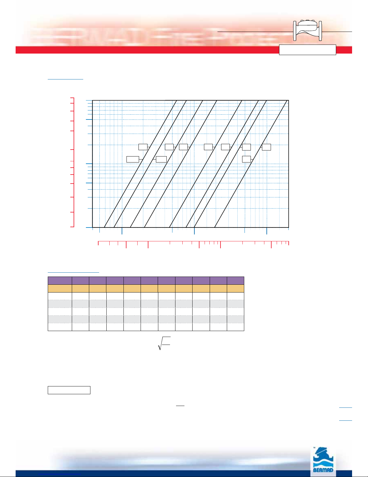
FP 400E Flow &Hydraulic Data
5678
10
15
20
30 440050 60 80
100
15020020 3000300500600800
1000
2000
0.01
0.05
0.1
0.5
1.0
2
1/2
"
3" 4" 6" 8" 10"
12"
bar
m3/h
psi
1.5
2.5
5.0
7.5
10.0
12.5
15.0
0.15
0.25
0.5
0.75
1.0
1.25
20 30 40 50 75 100 500 1,000 5,000
gpm
Pressure Loss
11/2"
14"2"
Flow Chart
Flow Properties
DN 40 50 65 80 100 150 200 250 300 350
Inch 1½" 2" 2½" 3" 4" 6" 8" 10" 12" 14"
Kv 57 57 78 136 204 458 781 829 1,932 1,932
Cv 66 66 90 157 236 529 902 957 2,231 2,231
K3.2 3.2 4.2 2.9 4.0 4.0 4.4 3.9 3.6 3.6
Leq-m 9.1 9.1 12.1 13.7 14 27.4 45.8 108 57 57
Leq-feet 30 30 40 45 46 90 150 354 187 187
Valve flow coefficient, Kv or Cv Equivalent Pipe Length, Leq
Flow resistance or Head loss coefficient,
Cv = 1.155 Kv
Where:
Kv = Valve flow coefficient (flow in m3/h at 1bar Diff. Press.)
Cv = Valve flow coefficient (flow in gpm at 1psi Diff. Press.)
Q = Flow rate (m3/h ; gpm)
∆P = Differential pressure (bar ; psi)
Gf = Liquid specific gravity (Water = 1.0)
Kv(Cv)=Q Gf
∆P
Leq=Lk.D
K=∆H2g
V2
Where:
K = Flow resistance or Head loss coefficient (dimensionless)
∆H = Head loss (m ; feet)
V = Nominal size flow velocity (m/sec ; feet/sec.)
g = Acceleration of gravity (9.81 m/sec2; 32.18 feet/sec2)
Where:
Leq = Equivalent nominal pipe length (m ; feet)
Lk = Equivalent length coefficient for turbulent
flow in clean commercial steel pipe (SCH 40)
D = Nominal pipe diameter (m; feet)
Note:
The Leq values given are for general consideration only.
Actual Leq may vary somewhat with each of the valve sizes.
3

BERMAD Fire Protection
400 Series
FP 400E Dimensions &Weights
Size DN mm (inch) 40 (1½”) 50 (2”) 65 (2½”) 80 (3”) 100 (4”) 150 (6”) 200 (8”) 250 (10”) 300 (12”) 350 (14”)
ANSI #150, ISO PN 16
LF (mm) 205 205 205 257 320 415 500 605 725 741
W (mm) 155 155 178 200 223 306 365 405 610 597
H (mm) 74 74 86 110 130 205 256 256 373 373
RF (mm) 64 78 89 100 115 140 172 204 242 267
a (1) (inch) ½ ½ ½ ½ ½ ½ ½ ½ ½ ½
b (1) (inch) ¼¼¼¼¼¼¼¼¼¼
c (1) (inch) ½½½½½½½½½½
d (2) (inch) ¾ ¾ 1.5 1.5 2 2 2 2 2 2
Control Vol.(3) (Lit.) 0.12 0.12 0.18 0.29 0.67 1.94 3.86 3.86 13.8 14
Weight (Kg) 8 9 10.5 19 28 68 125 140 220 235
Metric
Si
Flanged
Grooved Threaded
LG
a
d
a
RG
H
LT
a
d
a
RT
H
a
d
LF
RF
H
a
b
Cb
b
W
Flanged Grooved
Threaded
Size DN mm (inch) 50 (2”) 80 (3”) 100 (4”) 150 (6”) 200 (8”)
Grooved
LG (mm) 205 250 320 415 500
W (mm) 120 175 200 306 365
H (mm) 74 110 130 205 256
RG (mm) 30.2 44.5 57.2 84.2 110
a (1) (inch) ½ ½ ½ ½ ½
b (1) (inch) ¼ ¼ ¼ ¼ ¼
c (1) (inch) ½ ½ ½ ½ ½
d (2) (inch) ¾ 1½ 2 2 2
Control Vol.(3) (Lit.) 0.12 0.29 0.67 1.94 3.86
Weight (Kg) 5 10.6 16.2 49 108
Size DN mm (inch) 40 (1½”) 50 (2”) 65 (2½”)
ISO-7-Rp or NPT(F)
LT (mm) 180 180 210
W (mm) 120 120 129
H (mm) 74 74 87
RT (mm) 30 37.5 40
a (1) (inch) ½ ½ ½
b (1) (inch) ¼ ¼ ¼
c (1) (inch) ½ ½ ½
d (2) (inch) ¾ ¾ 1½
Control Vol.(3) (Lit.) 0.12 0.12 0.18
Weight (Kg) 4 4 5.7
(1) (a), (b), (c) are NPT Thread ports
(2) (d) is BSPT threaded drain port
(3) (Control Volume) is Control Chamber Displacement Volume of Liquid pushed when valve opens
4

BERMAD Fire Protection
400 Series
FP 400E Dimensions &Weights
Size 1½ 22½ 346810 12 14
ANSI #150, ISO PN 16
LF (inch) 81/881/881/8101/8125/8163/8195/82313/16 284/8291/8
W (inch) 61/861/87 77/886/812 143/816 24 234/8
H (inch) 27/827/833/843/851/881/8101/8101/8145/8145/8
RF (inch) 24/831/834/837/844/854/866/88 94/8104/8
a (1) (inch) ½ ½ ½ ½ ½ ½ ½ ½ ½ ½
b (1) (inch) ¼ ¼ ¼ ¼ ¼ ¼ ¼ ¼ 3/83/8
c (1) (inch) ½½½½½½½½½½
d (2) (inch) ¾ ¾ 1.5 1.5 2 2 2 2 2 2
Control Vol.(3) (Gal.) 0.03 0.03 0.05 0.08 0.18 0.51 1.02 1.02 3.65 3.70
Weight (Lbs.) 18 20 23 42 62 150 276 309 485 518
English
US
Flanged
Grooved Threaded
LG
a
d
a
RG
H
LT
a
d
a
RT
H
a
d
LF
RF
H
a
b
Cb
b
W
Flanged Grooved
Threaded
Size (inch) 2 3 4 6 8
Grooved
LG (inch) 81/16 913/16 125/8165/16 195/8
W (inch) 4¾ 67/877/8121/16 143/8
H (inch) 215/16 45/16 51/8129/16 101/8
RG (inch) 13/16 1¾ 2¼ 3¼ 43/8
a (1) (inch) ½ ½ ½ ½ ½
b (1) (inch) ¼ ¼ ¼ ¼ ¼
c (1) (inch) ½ ½ ½ ½ ½
d (2) (inch) ¾ 1½ 2 2 2
Control Vol.(3) (Gal.) 0.03 0.08 0.18 0.51 1.02
Weight (Lbs.) 11 23 36 108 238
Size (inch) 1½ 22½
ISO-7-Rp or NPT(F)
LT (inch) 71/16 71/16 81/4
W (inch) 43/443/451/16
H (inch) 27/8215/16 37/16
RT (inch) 13/619/16 19/16
a (1) (inch) ½ ½ ½
b (1) (inch) ¼ ¼ ¼
c (1) (inch) ½ ½ ½
d (2) (inch) ¾ ¾ 1½
Control Vol.(3) (Gal.) 0.03 0.03 0.05
Weight (Lbs.) 9 9 13
(1) (a), (b), (c) are NPT Thread ports
(2) (d) is BSPT threaded drain port
(3) (Control Volume) is Control Chamber Displacement Volume of Liquid pushed when valve opens
5
BERMAD Fire Protection
400 Series
FP 400E Installation, Operation &Maintanence
Installation
Proper operation of the FP 400E Deluge Valves depends
upon their trim being installed in accordance with the
appropriate trim configuration.
Notes:
■Wet pilot height should not exceed “Maximum
Elevation Above Valve" (see data for specific model).
■Any deviation in trim size or arrangement may
adversely affect the proper operation of the deluge
valve.
■All the pilot system devices, must be UL Listed and
compatible with the particular deluge system. Refer
to current “UL Listed Fire Protection Equipment
Directory”.
Warning: The deluge valve and trim must be installed
only in areas where they will not be subject to freezing
temperatures.
Installation Instructions
1. Allow enough room around the valve assembly for
any adjustments and future maintenance.
2. Before the valve is installed, flush the pipeline to
remove any dirt, scale, debris, etc. Not flushing the
line may result in the valve being rendered
inoperable.
3. Install the valve in the pipeline so that the valve flow
arrow appearing on the body casting is pointing in
the desired direction. Ensure that the valve is
positioned so that the cover can be easily removed
for future maintenance.
4. Ensure that the Control Trim is mounted properly
and all other components are positioned correctly
as per illustration.
5. After installation in the main line, carefully inspect/
correct any damaged accessories, piping, tubing, or
fittings. Ensure that there are no leaks.
6. Install the components comprising the Deluge Trim
Package in their proper positions in compliance with
all instructions, drawings, and technical
specifications describing the BERMAD Deluge
Valve, according to the relevant illustration.
7. All additional accessories, although not packed
together with the BERMAD Deluge Valve, must be
installed as shown in the relevant P&ID and other
illustrations.
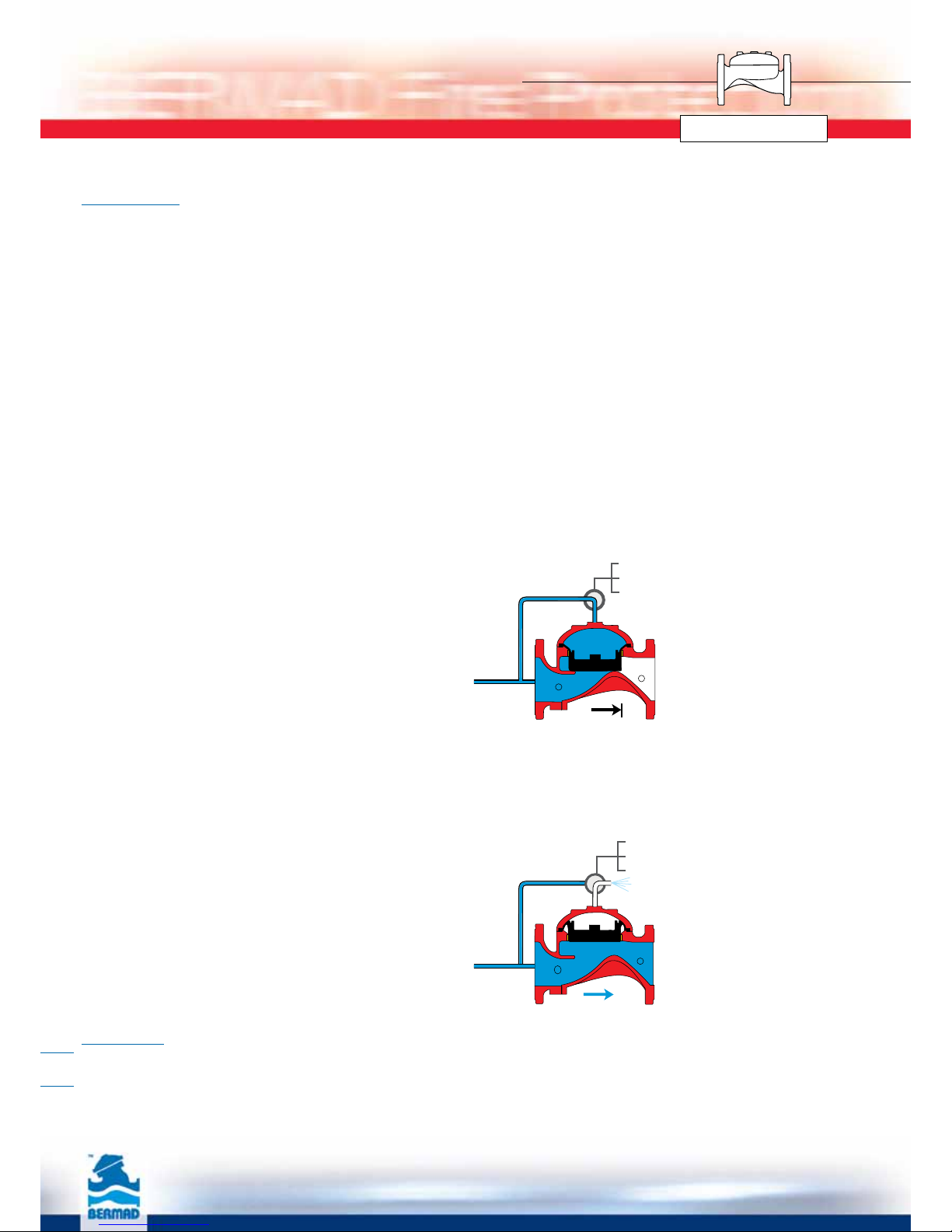
Operation
Principle of Operation
The BERMAD FP 400E Deluge Valve (assembled with
specific trim) is suitable for systems that include
adequate detecting and piping systems with open
nozzles. The deluge valve prevents water from entering
system piping until required. The deluge valve is kept
closed by pressure applied to the control chamber
through a restricted priming line.
In the SET position, the water pressure supplied through
the priming line is trapped in the control chamber of the
deluge valve by a check valve, and by the normally
closed release device.
The pressure trapped in the control chamber of the
deluge valve presses the valve seal disc down, thereby
sealing the valve and keeping the system piping dry.
Under Test or Fire conditions, when the pressure is
released from the control chamber by the opening of the
automatic releasing device or by manual release, the
deluge valve opens and allows the inlet supply water to
flow through the valve and into the system piping and
alarm devices.
Warning: Whenever the handle of the Manual
Emergency Release is pulled, pressure is released from
the control chamber, the deluge valve will open, and
water will flow into system piping and alarm devices.
Electric
Pneumatic
Hydraulic
Electric
Pneumatic
Hydraulic
Valve Closed (Set Position)
Line pressure applied to the control chamber of the
valve creates a superior force that moves the valve to
the closed position and provides drip tight sealing.
Valve Open (Operating Conditions)
Releasing the pressure from the control chamber to
atmosphere or some other lower pressure zone causes
the line pressure acting on the seal disc to move the
valve to the open position.
6

BERMAD Fire Protection
400 Series
FP 400E Installation, Operation &Maintanence
Placing in Service/Resetting
The deluge valve and the control trim shall be Place in
Service with accordance to the most recent IOM
procedures for the specific model.
After all relevant instructions are performed, slowly open
the supply-isolating valve and check that no water flows
into the system.
The system is now operational and in stand-by mode.
Maintenance
Bermad Deluge Valves require no lubrication, no packing
tightening, and require minimum maintenance.
Removing the System from Service
Warning: When taking a deluge system out of service,
a fire patrol should be established in the system area.
If automatic fire alarm signaling equipment is utilized,
the proper authority should be notified that the system
is being removed from service. The insuring body and
owner’s representative should also be notified when the
system is being taken out of service.
WARNING:
Do not turn off the water supply to make repairs without
placing a roving fire patrol in the area covered by the
system. The patrol should continue until the system is
back in service.
Prior to turning off any valves or water supply, notify local
site fire officials.
Removal Instructions
1. Shut off the main supply-isolating valve.
2. Close the priming line valve to the deluge valve
control chamber.
3. Open all drain valves.
4. Release the water pressure from the control chamber
of the deluge valve by pulling the manual emergency
release.
5. Place “Fire Protection System Out of Service” signs in
the area protected by the system.
Inspection and Testing
1. Warning: Do not turn the water supply off to make
repairs without placing a roving fire patrol in the area
covered by the system. The patrol should continue
until the system is back in service.
2. Prior to turning off any valves or activating any
alarms, notify local security guards and the central
alarm station, if used, to avoid signaling a false alarm.
3. The deluge valve and the control trim shall be
maintained with accordance to the most recent IOM
procedures for the specific model. A periodic test
schedule should be established also with accordance
to the site conditions and owner regulations.
4. Take all additional measures as required by NFPA-25
“standard for the inspection, testing, and
maintenance of water-based fire protection systems”.
5. The system should be checked weekly for “Normal
Conditions”.
6. Clean the priming strainer prior to any resetting of the
deluge valve.
7. The deluge valve must be activated at full flow at
least annually. Take all necessary precautions to drain
water and prevent damage in the area protected by
the system.
8. After about five years of operation, replacement of the
diaphragm assembly is recommended. Remove the
cover, clean the valve body from sediments, clean the
control tubing entry holes, and install a new
diaphragm assembly in place.
Spare Parts
1. The Diaphragm Assembly is the only spare part
needed for the main deluge valve, see attached
“Valve Disassembly and Parts Breakdown Illustration”.
2. It is not recommended to store spare rubber parts for
long periods (rubber in improper storage conditions
can harden and crack).
3. Contact your Bermad representative and order new
rubber parts when required.
7
BERMAD Fire Protection
400 Series
FP 400E Installation, Operation &Maintanence
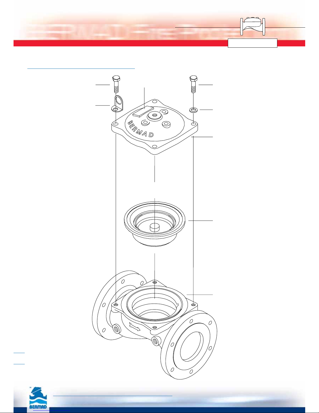
Valve Disassembling Parts Breakdown
Lifting Ring
Body
Diapragm
Assembly
Cover
Disk
Bolt
Bolt Va lve name plate
The information herein is subject to change without notice. BERMAD shall not be held
liable for any errors. All rights reserved. © Copyright by BERMAD. PT4PE08-DATA
8
This manual suits for next models
1
Table of contents
Popular Lawn And Garden Equipment manuals by other brands

Sunforce
Sunforce SOLAR user manual

GARDEN OF EDEN
GARDEN OF EDEN 55627 user manual

Goizper Group
Goizper Group MATABI POLMINOR instruction manual

Rain Bird
Rain Bird 11000 Series Operation & maintenance manual

Cub Cadet
Cub Cadet BB 230 brochure

EXTOL PREMIUM
EXTOL PREMIUM 8891590 Translation of the original user manual


Vertex
Vertex 1/3 HP Maintenance instructions

GHE
GHE AeroFlo 80 manual

Land Pride
Land Pride Post Hole Diggers HD25 Operator's manual

Yazoo/Kees
Yazoo/Kees Z9 Commercial Collection System Z9A Operator's & parts manual

Premier designs
Premier designs WindGarden 26829 Assembly instructions

Snapper
Snapper 1691351 installation instructions