BERMAD M10 User manual

Instruction Manual
ELECTROMAGNETIC FLOW METERS
M10
INSTRUCTION MANUAL
CAREFULLY READ THESE INSTRUCTIONS AND KEEP THEM IN A SAFE PLACE

M10
Instruction Manual
2
This document must be delivered to the user before machine installation and commissioning.
Symbols used in this manual
In order to draw the attention of all personnel working with the equipment supplied by BERMAD, the points
of particular importance described in this manual are highlighted with graphic signs and dierent colors
that will make them easily identifiable.
Legend
CAUTION! This sign indicates a risk of electric shock! All operations marked with this sign must be performed
exclusively by qualified technical personnel.
CAUTION/WARNING. This symbol indicates vital information and points to be observed. Please refer to
the related documents.
NOTE. This symbol indicates information and points of particular importance to be observed.
READ THE INSTRUCTIONS CAREFULLY AND KEEP THEM IN A SAFE PLACE
This manual can be downloaded from the web site www.euromag.com in the Area Download section. We
want you to save time and money!
We assure you that, having read this manual thoroughly, you will be able to perform correct installation
and fully use the product in total safety.

Instruction Manual
33
1 INTRODUCTION 5
1.1 MANUFACTURER’S STATEMENT 5
1.2 PACKAGING VERIFICATION 5
1.3 PRELIMINARY NOTES 6
1.4 PRODUCT IDENTIFICATION 7
1.5 APPLICATIONS 8
2 PRODUCT DESCRIPTION 9
2.1 OPERATING PRINCIPLE 9
2.2 POWER SUPPLY 9
2.3 DATA SAFETY 10
3 TECHNICAL SPECIFICATIONS 11
3.1 OVERALL DIMENSION 11
3.2 CERTIFICATES AND APPROVALS 12
3.3 GENERAL TECHNICAL FEATURES 13
3.4 MEASURING ACCURACY 14
3.4.1 Reference conditions: 14
3.4.2 Accuracy class 14
3.4.3 MID Annex III (MI-001) - (Directive 2014/32/EU) 15
4 INSTALLATION 16
4.1 STORAGE AND MOVING 16
4.1.1 Storage 16
4.2 GENERAL INSTALLATION REQUIREMENTS 16
4.2.1 Vibrations 16
4.2.2 Magnetic fields 17
4.2.3 Negative pressure 17
4.2.4 Protection from direct sunlight 17
4.2.5 Operating temperatures 17
4.3 INSTALLATION CONDITIONS 18
4.3.1 Positioning in relation to the plant 18
4.3.2 Important guidelines for correct installation 18
4.4 INSTALLATION 22
4.4.1 Important instructions on installation 22
4.4.2 Sensor support 23
4.5 HOW TO AVOID AIR POCKETS IN THE PIPELINES 24
4.6 ELECTRICAL CONNECTION 28
4.6.1 Wiring diagram 28
4.6.2 Connection options I/O 30
4.6.2.1 Pulse output 30
4.6.2.2 RS485 - 2 wire interface 30
4.6.3 Electrical grounding of the meter 32
4.6.3.1 Plastic Pipe Installation using Grounding Rings 32
4.6.3.2 Metal Pipe Installation 33
4.6.4 Connection to the power supply 33
4.7 BATTERY INSTALLATION 34

M10
Instruction Manual
4
5 METER PROGRAMMING 36
5.1 DISPLAY 36
5.2 FIRST ACTIVATION 37
5.3 USER INTERFACE 38
5.4 DISPLAY TEST 39
5.5 FUNCTIONS 39
5.5.1 List of functions available through display interface 41
5.6 BATTERY 42
5.7 ACCESS VIA MAG-NET APP 43
5.8 ACCESS VIA EUROMAG-LINK 44
5.8.1 Access via RS485 44
5.8.2 Access via Bluetooth 45
5.9 FIRMWARE UPDATE 47
5.10 DEVICE RESET 49
5.10.1 Reboot 49
5.11 METERS SUBJECT TO LEGAL METROLOGY 50
5.11.1 Metrological seals 50
5.11.2 Utility seals 50
6 MAINTENANCE 51
6.1 CABLE GLAND CLOSING AND GASKET CONDITION CHECK 51
6.2 BATTERY INSTALLATION/REPLACEMENT 51
7 TROUBLESHOOTING 52
7.1 MALFUNCTIONING AND POSSIBLE SOLUTIONS 52
7.2 SELF DIAGNOSTIC 53
8 PRODUCT DISPOSAL 55

Instruction Manual
55
1 INTRODUCTION
IMPORTANT WARNING! It is very important that all personnel working with the equipment have read and
understood the instructions and indications provided in this manual, and that they follow them prior to
using the equipment itself. The manufacturer assumes no responsibility for the consequences resulting
from improper use by the worker.
The worker will be responsible for the suitability of the device for particular purposes.
The warranty will be considered void in case of improper installation and use of devices (systems).
The manufacturer shall bear no responsibility for any damage caused by improper use, improper
installation or tampering of own products. Installation, connection, commissioning and maintenance
must be carried out by personnel who are qualified and authorized for this purpose. The personnel in
charge of the installation must make sure that the measurement system is properly connected as per
the wiring diagram indicated in this document.
The manufacturer shall bear no responsibility for any damages or injuries resulting from any misunderstanding
of this manual. In order to avoid possible accidents to persons or things caused by incorrect interpretation
of the instructions, the user must not proceed with operations and/ or interventions on the meter if
there are uncertainties or doubts regarding the operation(s) to be performed. We recommend contacting
Assistance Service for clarifications in this regard for more precise instructions.
The manufacturer will be held responsible only if the meter will be used in its original configuration.
For applications that require high working pressures or use of substances that may be dangerous for
people, the environment, equipment or anything else: In case of pipe breakage, BERMAD recommends to
take the necessary precautions such as adequate positioning, protection or installation of a guard or safety
valve, before installing the meter.
The device contains live electrical components, therefore installation, checks and maintenance must be
carried out by experienced and qualified personnel who are aware of all necessary precautions to be taken.
Before opening any internal part, please disconnect the power supply.
1.1 MANUFACTURER’S STATEMENT
Stresses and loads possibly caused by earthquakes, strong winds, fire damage, vibrations and natural
disasters were not taken into account in the phase of product designing.
Do not install the product in such a way that it acts as a focus for stresses on the pipes. External loads
were not taken into account in the device configuration.
While the device is working, the pressure, supply voltage and/or temperature values indicated on the
label or in this Operating Manual must not be exceeded.
1.2 PACKAGING VERIFICATION
At the moment of purchase and/or upon receipt of the product, the buyer is strongly advised to check the
quality of the packaging which must be intact, without visible dents and completely and correctly closed.
When opening the packaging, also check that the product complies with the information on the packing
list in terms of completeness of components/accessories.
NOTE: All BERMAD software packages are available on the USB flash drive key that accompanies the product.
The software can also be downloaded from the website www.euromag.com by accessing the Download
Area. A free registration will be required after which you can download the configuration software for
your product.

M10
Instruction Manual
6
1.3 PRELIMINARY NOTES
The M10 is a reduced bore electromagnetic flowmeter, made of thermoplastic material equipped with grooved
connection system, available in sizes DN50/2” - DN150/6”, and with an integrated electronic converter.
Like other electromagnetic flowmeters it has many important advantages compared to its mechanical
counterparts, such as: exceptional long-term stability, maximum process reliability and zero maintenance.
As a result, these sensors can provide accurate and reliable long-term measurements.
See the following paragraphs for more detailed information on correct installation.
Main parts of the M10 meter are:
Flow tube
Meter enclosure
Battery compartment
Label
Grounding stud
Connection cable/connector
Protective cover
Display
Battery Holder
Grounding Stud
Connection Cable Connector
Flow Tube
Label
FRONT BACK
(Connection cable confiiguration)
BACK
(Connector confiiguration)
Meter Enclosure
Battery Compartment
Positive flow direction Victaulic OGS connection system
Display
Protective cover
TOP SIDE

Instruction Manual
77
The M10 meter is equipped with a magnet for magnetic reed operation.
NOTES:
Electromagnetic flowmeters are designed specifically to operate under the following basic
conditions:
1. The liquid must be conductive
2. The tube must always be completely full
3. The input and output distances must be according to the recommended settings
4. The grounding instructions must be followed
1.4 PRODUCT IDENTIFICATION
Each M10 manufactured by BERMAD has a STANDARD identification plate
(Fig. 1) or MID (Fig. 2), that displays the following information:
STANDARD PLATE:
CE conformity mark.
MODEL: Instrument Model
S/N: Meter Serial Number
Size: Nominal diameter
PN: Pressure class
Qmax: Max flow rate
IP: Degree of protection
12Vdc / Battery: power supply, to be selected during
commissioning
This symbol means that the product must be
disposed of according to the legal requirements.
Fig. 1 STANDARD Identification Plate
Model: M10
S/N: N7K0056
Size: DN80/3”
PN: 16 bar
Qmax: 100 m
3
/h
IP: 68
12VDC
BATTERY
PN: M070080G16PF2AB

M10
Instruction Manual
8
MID IDENTIFICATION PLATE:
CE conformity mark
Model: Instrument Model
S/N: Meter Serial Number
DN80/3”. PN16: Nominal diameter and MAP
Q3: permanent flow rate
R: ratio
∆p: pressure loss class.
M1 O: Environmental Class
E2: Electromagnetic class
T: Non resettable totalizers
P: Resettable totalizers
12Vdc / Battery: power supply, to be selected during
commissioning
Rep.: Date within battery must be replaced
This symbol means that the product must be
disposed of according to the legal requirements.
The identification plate must never be removed, damaged or changed. It must also be kept clean from
any dirt deposits, as the data contained are the only safe and unambiguous way to recognize the type of
flowmeter and it allows to complete the repair request form attached to this manual.
1.5 APPLICATIONS
M10 is widely used for purposes in which it is important to measure the flow rate of electrically
conductive liquids. Examples of typical applications for the M10 meter are:
Irrigation
Greenhouses
Waterworks
DMA District Metered Areas
Leak detection systems
Remote applications without access to electrical grid
Building and Cooling Systems
Fig. 2 MID
M10
S/N: N7K0059
DN80/3” - PN16
R400
T50
∆p16
M1
E1
IP68
PN: M070080G16PF2AB
T: Noon resettable P: Resettable
12VDC
BATTERY
- Rep. mm/aaaa
M21
0122
Instruction Manual
99
2 PRODUCT DESCRIPTION
2.1 OPERATING PRINCIPLE
M10 has been designed with the aim of fulfillment of all the requirements of modern water management
systems, through a flexible and hybrid electronics which, depending on the model, oers various power
supply solutions.
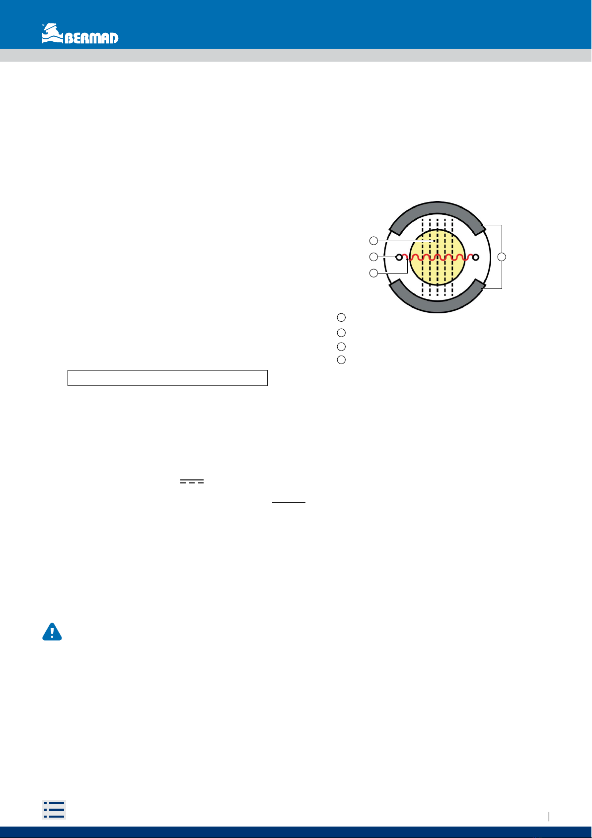
An electromotive force is induced at the ends of a
conducting fluid that moves with velocity v in a magnetic
induction field B and can be expressed as:
e = kBDv
Where it is:
Bis constant by construction;
Dis constant and represents the distance between
the electrodes E1 and E2 (equivalent to the diameter
of the flowmeter);
vis the fluid velocity;
kis the calibration constant;
emf «e» is proportional to the velocity «v»
2.2 POWER SUPPLY
The M10 meter is available with three dierent power supply setup:
Battery-powered via a lithium battery (LiSOCL2)
Mains powered 12Vdc
Mains powered 12Vdc with backup lithium battery
It the case of lithium battery power supply is used; it is necessary to consider the following cautions:
Lithium batteries are the primary energy source because of their high-energy density, and are made to
meet the highest safety standards. However, they can be potentially hazardous if they are exposed to
electrical or mechanical abuse. In many cases, this is associated with excessive heat production in which
the increased internal pressure could lead to cell rupture.
These basic precautions need to be followed when handling and using lithium batteries:
IMPORTANT INSTRUCTIONS!
Do not short-circuit, recharge, overload or reverse-connect the battery
Do not expose the battery to temperatures higher than those specified, as it will incinerate
Do not crush, puncture or open the cells or disassemble the battery packs
Do not weld or solder the battery body or battery packs
Do not expose the contents to water
The use of lithium batteries is regulated under the United Nations Model Regulations on the Transport of
Dangerous Goods (UN Model Regulations on the Transport of Dangerous Goods), document ST/SG/ AC.10/1/
Rev.22.
1 - Electromotive force (proportional to the velocity);
2 - Electrodes;
- Magnetic field;
3
4 - Coils;
1
2 4
3

M10
Instruction Manual
10
These are basic precautions that should be followed during the transport of lithium batteries:
IMPORTANT NOTES!
Transport only in special packages with labels and special transport documents specific to current regulations.
Be careful when handling, transporting and packing the batteries so as to avoid short- circuiting.
The batteries comply with the requirements set out in the “UN Manual of Tests and Criteria, Part III,
subsection 38.3” for air transport and with the provisions of the ADR regulations for transport by truck/ship.
Remove the battery from the transmitter before sending the flow meter to BERMAD in case of maintenance
or of any intervention under warranty.
2.3 DATA SAFETY
The M10 meter guarantee the security of the collected and processed data as a result of the internal
memory (EEPROM) on which the data are saved.
The integrated memory allows the storage of data with 100,000 log lines (the data are kept for more than 6
years with factory settings); when the memory is full, the new data will automatically overwrite the old data.
In order to prevent the loss of saved data, and to be able to better manage it on its management systems,
the unit is supplied with a specialized software that allows users to communicate with the electronics of
the M10 via Bluetooth or RS485 communication interfaces, that can be connected to any PC, laptop and/or
tablet with a Windows operating system, it is also possible to interface with the “Mag-Net” mobile software
in iOS and Android smartphones and tablets.
Fast download, data management, easy programming and an advanced self-diagnosis system, that
automatically perform a wide range of essential checks, make the M10 converter a highly ecient and
irreplaceable tool for fluid detection in water management systems.
A multi-level password system also allows controlled access to the data collected and guarantees confidentiality.

Instruction Manual
1111
3 TECHNICAL SPECIFICATIONS
3.1 OVERALL DIMENSION
The overall dimensions of M10 are shown below.
L2
Di
L3L4
De
L1
L2
Size De L1 L2 L3 L4
DN50 / 2” 60.3 230 100 150 200
DN80 / 3” 88.6 230 100 150 225
DN100 / 4” 114.3 230 100 150 250
DN150 / 6” * 168.3 300 100 210 300
* DN150/6” Version are indicative

M10
Instruction Manual
12
3.2 CERTIFICATES AND APPROVALS
MARKING
The device complies with the requirements of the applicable EU directives.
These are listed together with the applied standards in the relevant
EU Declaration of Conformity.
Electromagnetic compatibility
Directive 2014/30/EU
Harmonised standards: EN 61326-1
Radio Equipment
Directive 2014/53/EU
Harmonised standards:
ETSI EN 301 489-1
ETSI EN 301 489-17
Measurement Instrument Directive
2014/32/EU
Harmonised standards: EN ISO 4064 (OIML 49)
RoHS
Directive 2011/65/EU
Harmonised standards: EN IEC 63000
Other certification and
international standards
ISO 20456: Measurement of fluid flow in closed conduits
OIML R49: Water meters for cold potable water and hot water
OIML D11: General requirements for measuring instruments
EN IEC 60529: Degrees of protection provided by enclosures

Instruction Manual
1313
3.3 GENERAL TECHNICAL FEATURES
The table below contains the technical data of the M10.
Features M10
Structure
Integral Flow meter
DN Range
DN50/2” ÷ DN150/6”
Nominal Pressure
16 bar
Process Connection
Victaulic OGS
Fluid Conductivity
> 20 µS/cm
Process Temperature Range
0 ÷ 80 °C (32 ÷ 176 °F)
Materials in contact with
water
Flow tube: Glass fibre reinforced plastic
Electrodes: AISI316L
Power supply
Battery Powered: 3.6 V Lithium Battery
Mains Powered: 12Vdc (10.8 ÷ 13.2V), max 100mA
Consumption
0,25W÷1W (Mains powered)
Outputs
2 passive outputs (1 programmable), SSR Type (dry contact), galvanically insulated
Max. load +/- 35VDC, 100 mA protected against short circuits, minimum pulse
duration 5ms.
RS458 2 wire /half-duplex
Communication
Modbus RTU Slave
Bluetooth
Display
LCD Segment display, with dedicated status icons, 8+6 digits
User Interfaces
Magnetic reed
Bluetooth Mobile App
Euromag Link Software
Process memory
100,000 data lines
Programmable frequency 1 ÷ 120 minutes (15 minutes factory standard)
Metrological certificate
OIML R49-1:2013 / MID 2014/32/EU - Class 2 (if requested)
Temperature range
Ambient: -20 ÷ 60 °C (-4 ÷ +140 °F)
Process: 0 ÷ 80 °C (32 ÷ 176 °F)
Storage: -40 ÷ 70 °C (-40 ÷ +158 °F)
Technical units
m, m3, l, ML, ft3, gal
Totalizers
5 (2 Positive, 2 Negative, 1 Net)
Alarms and status icons
Status icons displayed and alarms recorded in the data logger
Self diagnostic
Excitation failure
Excessive ambient temperature
Wet electronic board
Low battery level / Mains voltage out of range
Pulses overlapping
Bluetooth communiccation error
Empty pipe
Measurement error
Software/memory malfunction
Mains power interruption
Software for communication
and programming
Bluetooth Mobile App - Mag-Net
Euromag Link Software (trough Bluetooth dongle, or RS485 interface)
Data Protection
Customizable password protection
EEPROM Memory with safe data storage management

M10
Instruction Manual
14
3.4 MEASURING ACCURACY
3.4.1 Reference Conditions:
Measuring liquid: water
Conductivity: >200 µs/cm
Temperature: 20°C
Pressure: 1 bar / 10Mpa
Upstream diameters: ≥ 5 DN
Downstream diameters: ≥ 3 DN
3.4.2 ACCURACY CLASS
ISO 20456: Q1÷Q2: ±0,45mm/s
Q2÷Q4: ±0,5% ±0.35mm/s
ISO 4064/OIML R49: R400 - Class 2

Instruction Manual
1515
3.4.3 MID ANNEX III MI001 DIRECTIVE 2014/32/EU
Flow characteristics
Water temperature class
T50 (+0,1 °C / +50 °C)
Maximum admissible pressure (MAP)
1,6 MPa (16 bar)
Orientation limitation
The sensor can be used in horizontal, vertical or diagonal position.
Flow profile sensitivity class
U0 and D0 (0 x DN upstream and 0 x DN downstream)
Reverse flow
The water meter is designed to measure reverse flow. The reverse flow is recorded on a separate volume
totalization. Also for reverse flow another pulse output is used.
Pressure loss class
∆p 16 (0,016 MPa or 0,16 bar)
Temperature range ambient
0°C/+55°C
Size Ø In and
Outlet [mm]
Flow rates [m3/h]
Minimum
Q1
Transitional
Q2
Permanent
Q3
Overload
Q4
Ratio
Q3/Q1
DN50 / 2” 50 0,10 0,16 40 50 400
DN80 / 3” 80 0,25 0,40 100 125 400
DN100 / 4” 100 0,40 0,64 160 200 400
DN150 / 6” 150 1,00 1,60 400 500 400

M10
Instruction Manual
16
4 INSTALLATION
4.1 STORAGE AND MOVING
4.1.1 Storage
To ensure the correct maintenance of the device while waiting for its installation, it is necessary to comply
with the storage provisions below:
1) Store the device in a dry place and protected from dust
2) Keep away from direct and continued sunlight
3) Keep the device in the original packaging until it is used
4) Temperature of the storage place: -40 ÷ +70 °C (-40 ÷ +158 °F)
4.2 GENERAL INSTALLATION REQUIREMENTS
IMPORTANT NOTE! THE SENSOR MUST ALWAYS BE COMPLETELY FULL OF LIQUID!
4.2.1 Vibrations
DO NOT expose the flowmeter to vibrations and/or movements that could aect its performance and
duration.
Install a suitable anti-vibration protection if vibrations occur.
AVOID EXCESSIVE
VIBRATIONS
AVOID EXCESSIVE
VIBRATIONS
AVOID EXCESSIVE
VIBRATIONS
Fig. 3 The pipe must always be completely full of liquid
Fig. 4 Avoid vibrations
Fig. 5 Installation with anti-vibration protections

Instruction Manual
1717
4.2.2 Magnetic fields
AVOID exposing the flowmeter to strong or nearby magnetic fields.
Fig. 6 Avoid magnetic fields
4.2.3 Negative pressure
Avoid vacuum conditions in the pipe. They can damage the coating of the flowmeter and move the electrodes
from their correct position.
4.2.4 Protection from direct sunlight
Protect the flowmeter if exposed to direct sunlight.
Fig. 7 Avoid direct exposure to sunlight
4.2.5 Operating temperatures
For normal and ecient operating of the flowmeter:
The ambient temperature must be limited within the range of (-25 ÷ +60) °C, (-13 ÷ +140) °F.
Fig. 8 Environment and fluid temperature limits
The process temperature must be limited within the range of (0÷ +80) °C, (32 ÷ +176) °F.
N S
N S
N S

M10
Instruction Manual
18
4.3 INSTALLATION CONDITIONS
4.3.1 Positioning in relation to the plant
To ensure optimal working conditions, the flowmeter must be installed correctly inside the system.
Correct and incorrect installation positions are described and illustrated below.
The flowmeter must remain below the hypothetical blue line (level line), which connects the two levels of
fluid to be measured (Fig. 9).
NOTE: Avoid placing the flowmeter above the piezometric level line (Fig. 10).
4.3.2 Important guidelines for correct installation
The M10 meter is designed to have the IP68 protection degree only when properly closed and tightened.
The manufacturer does not assume any responsibility for an improper closing by third parties.
For correct working conditions, please follow the important guidelines shown in the following figures.
Improper installation may result in an inaccurate measurement.
For partially filled pipes or with downward flow and free exit, the flowmeter should be placed in a
U-shaped tube (Fig. 11).
Fig. 9 Correct position Fig. 10 Incorrect position
Ideal installation
Fig. 11 Installation on U-shaped tube
Installation in limited spaces

Instruction Manual
1919
“T” connection upstream of the flowmeter
Fig. 12 Installation near "T" connection
Three-dimensional curves
Fig. 13 Installation near three-dimensional bends
IMPORTANT NOTE: THE SENSOR MUST ALWAYS BE COMPLETELY FULL OF LIQUID!
To ensure that the sensor is always completely filled with liquid, it is important to install it in the correct
position () and avoid all possible incorrect positions ().
This installation ensure that the
sensor is full of liquid.
This installation DOES NOT guarantee a
pipe full of liquid.
Fig. 14 Correct installation Fig. 15 Incorrect installation

M10
Instruction Manual
20
We recommend installing the sensor on a vertical/sloped pipe with an upward flow direction (Fig. 16) to
minimize the wear and deposits in the sensor. Avoid the installation on vertical pipes with free exit (Fig. 17).
Fig. 18 Correct (LH) and incorrect installation (central and RH)
Fig. 16 Correct position Fig. 17 Incorrect position
The position on the left ensure
that the sensor is full of liquid.
Central and right positions DO NOT
guarantee a pipe full of liquid.
Table of contents
Other BERMAD Measuring Instrument manuals


 instruction manual")


