Bernal S 201-60 User manual

S 201 01-07
1
Instruction manual
S 201
Please keep this manual in a safe place.
B 190.045-GB

S 201 01-07
2
Technical data

S 201 01-07
3

S 201 01-07
4
S 201 01-07
5
S 201 01-07
6

S 201 01-07
7
Instruction manual
Dear customer!
Congratulations on the purchase of this product.
This garage door operator has been developed according to state-of-
the-art technology and manufactured using the most reliable and high
quality electrical / electronic components.
We point out that this instruction manual is being released without
any warranty. We reserve the right to make changes or modifica-
tions on the equipment and on this manual at any time without
giving any prior notes.
Please keep this instruction manual in a safe place
near the garage door opener.
FOR THE SAFETY AND LIFE OF PERSONS IT IS
ESSENTIAL TO FOLLOW ALL INSTRUCTIONS.
Requirements for the garage and the door:
The garage door drive should only be implemented for the
automatic operation of spring-compensated swinging and
sectional doors in the non-commercial sector. The recom-
mended max. door measurements are listed in the chapter
Technical Data. The door has to be in accordance with the
valid specifications (e.g. EN 13241-1, EN 12604 and EN 12605).
Prior to installation of the operator the door must be easily
operated manually.
The opener is designed for operation in dry rooms.
The garage ceiling has to be constructed in a way that a safe
attachment of the opener is assured.
General safety instructions
Qualified and trained personnel with the following skills may only
carry out installation, connection and startup of the operator:
- knowledge and application of the most recent EN norms
in use.
- knowledge of the general and special safety and acci-
dent prevention regulations of the respective country.
- knowledge of the relevant electro-technical regulations
of the respective country.
Incorrect assembly may cause serious injury!
Prior to all work on the operator, disconnect the mains plug (except
in the case of test and programming processes).
Fit photo cells if the garage door opener is installed with access to
a public area. The photo cells must be checked in 6 month inter-
vals by qualified and trained personnel.
Do not operate the garage door opener at all, until it is confirmed,
that the garage door system is in accordance with the directive
98/37/EC and a valid EC-Declaration of Conformity has been
issued.
Warranty:
The manufacturer assumes no warranty and product liability if
installation was incorrectly performed or any change was made to
the drive without the latter’s prior consent. Mounting may only be
performed according to the assembly guidelines. The mounting or
additional use of other parts jeopardizes the safety of the drive and
is therefore prohibited.
Instructions for the installation of the operator
Please check if the door mechanics is in a proper condition: you
should be able to move the door very easy manually.
In addition all mechanical locking devices at the door must be put
out of action.
Permanently mounted auxiliary devices (such as push buttons
etc.) should be mounted within view of the door. The distance
between moving parts and the height must be at least 1.8 meters.
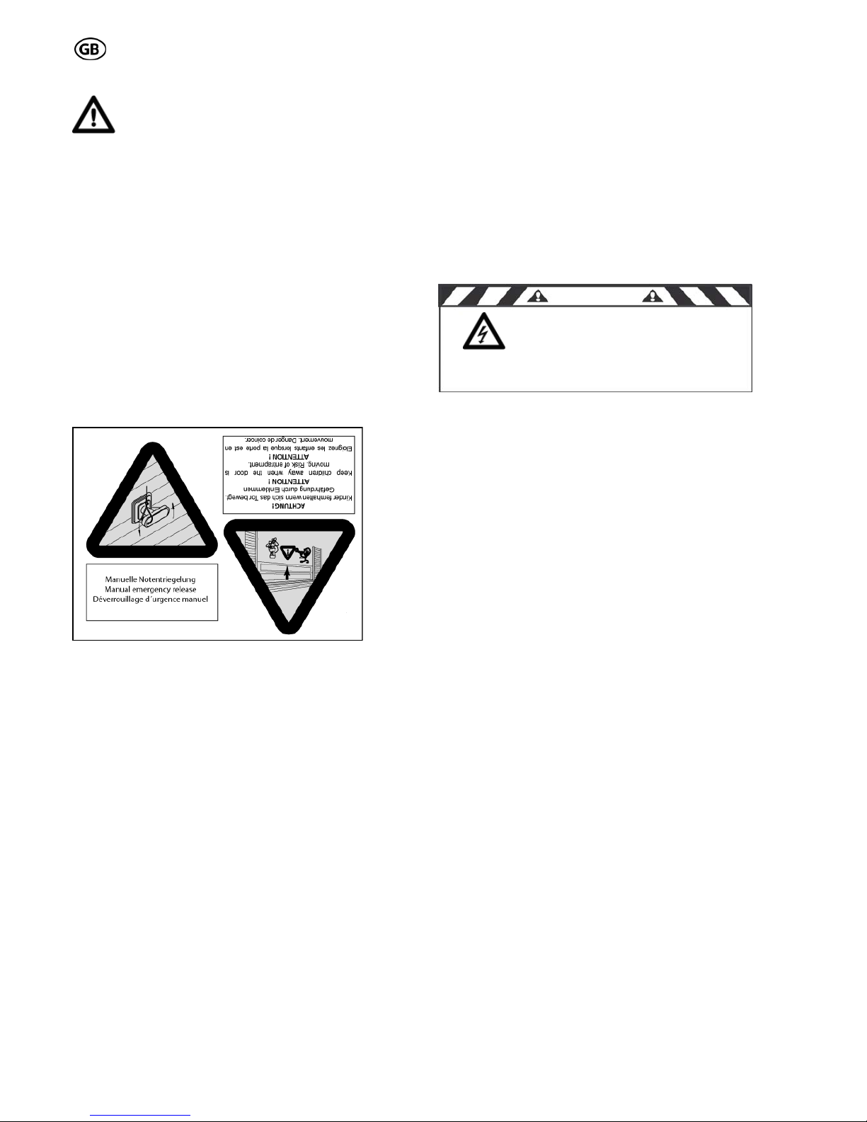
It is essential that they be mounted out of reach of children!
Affix warning signs indicating the risk of been caught in the door
where they may be seen immediately or in the vicinity of the per-
manently mounted push button.
An emergency release is required for garages without a second
access. A function test of the emergency release has to be carried
out monthly!
The door can shut down much faster if the springs are weak,
broken or damaged or if the counterweight is faulty. Under
these circumstances using the emergency release may lead
to uncontrolled movements of the door.
Instructions for the startup of the operator
Please inform all persons using the door system on how to operate
it correctly and safely. Demonstrate and test the reversion (with a
50 mm high obstacle at max. 150 N) as well as the mechanical
release.
Only operate the door if you have the entire door area in view.
Always be sure, that no persons or objects are located within
traveling range of the door.
Wait until the door has come to a complete halt. Persons or vehi-
cles are only allowed to step in the door operating area, when the
door is completely open and at a complete standstill.
Do not permit children to play with the automated garage door!
Transmitters are to be kept safe and away from children!
Door, opener and eventually extra installed safety accessories
have to be checked regularly. See also the chapter maintenance.
Do not use the operator when maintenance or adjustment
work is urgently required. A badly balanced door, or a faulty
garage door drive may cause damage and injuries.

S 201 01-07
8
Opener assembly
1./2. Scope of supply:
The scope of supply may differ from the shown components ac-
cording to the opener version.
3. Required tools
For the assembly and mounting of the opener the tools shown in
the figure are required (not included in the scope of supply).
4./5. Requirements for installation
The garage door opener is suitable for the automation of spring
balanced tilt doors and sectional doors (max. recommended di-
mensions see chapter Technical data).
For optimal attachment of the push rod to the sectional door, a
sectional door attachment is available as an accessory.
For the mounting of the opener a minimum lintel height of 35 mm
is necessary.
6. Pre-assembly of the rail
According to the version, the rails have to be pre-assembled first.
First connect the rail parts with the connecting rails. Slide the rails
together as far as it will go to the stop position.
7. Assembly of the drive adapter
Press the pinion into the bearing. Pay attention that the belt is not
seized. Then attach the transport protection and push the com-
plete assembly into the rail.
8./9. Assembly of the fastening device
Pull the chain or belt lying in the rail towards the open rail end.
Pay attention that the driver (a) is on the correct side of the rail.
Then fix the idler pulley at the fastening device as shown. Pay
attention that the square coach bolt fits correctly into the bracket of
the idler pulley.
Now pre-tension the chain or belt by turning the nut so far that the
chain or belt does not sag any more.
10. Trolley test
Check afterwards, that the trolley can easily be moved by hand. To
release the trolley from the chain lock, push the lever on the trolley
and at the same time move the trolley in the rail.
Make absolutely sure, that after this test the trolley engages on the
driver. To perform this, move the trolley without holding the lever
over the driver and the trolley engages automatically.
11. Assembly of the door bracket
The push rod components included in the KIT can be combined
according to each different installation situation.
If the push rod is not long enough you have got the possibility to
extend it with the extension piece. For the installation of the opener
on a sectional door we recommend the use of the sectional door
angle.
Then the push rod must be fixed on the provided door bracket.
12. Remove the light cover
Loosen the screw from the light cover and remove the light cover.
13. Mount the drive head to the rail
Attach the motor shaft of the drive head to the pinion in the rail.
Then fix the drive head with the provided screws.
14. Mark the middle of the door
Measure the width of the door and mark the middle of the door at
the lintel and on the ceiling of the garage.
15./16. Determination of the necessary height
The rail has to be mounted on such a height that between the
highest door point (a) (the highest point that the door can reach
during the movement) and the lower edge of the rail (b), a clear-
ance of at least 10-20 mm is existent.
Pay attention, that the rail is always mounted horizontally.
The angle αmay not exceed 30°, otherwise a correct transmission
of the force is not guaranteed.
The distance between the lower edge of the rail and the upper
edge of the garage door should be between 5 and 7 cm in closed
condition.
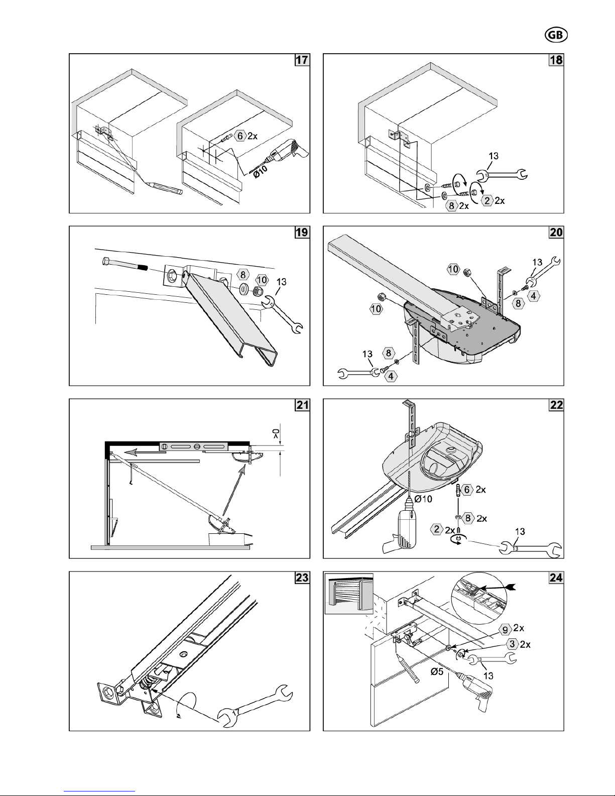
17./18. Mounting the lintel bracket
Fix the provided lintel bracket to the lintel considering the deter-
mined measurements (middle of the door, height) (depending to
the installation situation it may be necessary to replace the pro-
vided fastening screws by others.
Attention: When drilling, cover the opener!
19. Attachment of the rail to the lintel
Then fix the rail at the lintel bracket.
20. Mounting of the perforated angles
The perforated angles have to be fixed to the motor head. The
required measurements result from the before determined installa-
tion height of the rail (make sure that the rail is mounted horizon-
tally!)
21./22. Attachment of the opener to the ceiling
Then fix the opener to the ceiling of the garage. Make sure, that
the rail is aligned with the earlier marked middle of the door.
Attention: When drilling, cover the opener!
23. Tension of the chain or belt
Turn the nut of the tension unit so far that the spring is completely
compressed. Then release the tension of the spring by turning the
nut back about 1 or 2 turns.
24. Attachment of the door bracket assembly
Release the trolley manually and move it towards the lintel.
Attach the door bracket firmly to the door with at least 2 screws.
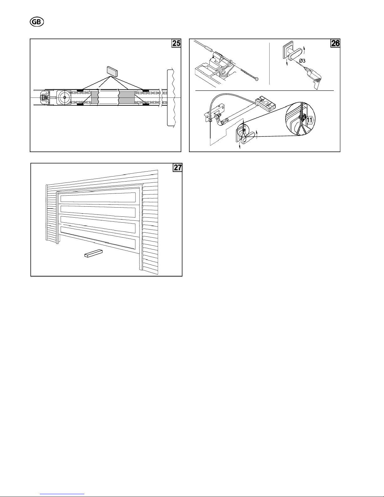
25. Insert the rubber pads
If you have a chain drive we recommend to stick the provided self-
adhesive rubber pads to the inside of the rail in order to minimize
the noise level. Please make sure that the rubber pads are not
fixed in the travel path of the trolley.
26. Installing the emergency release
If the garage is without a second entrance, the installation of a
emergency release set is absolutely necessary, so that in case of
an emergency the door can be opened from outside.
It is absolutely necessary to check the correct function of the
emergency release before starting up the garage door opener.
IMPORTANT INSTRUCTIONS FOR A SAFE
MOUNTING
ATTENTION – INCORRECT MOUNTING MAY LEAD
TO SERIOUS INJURY – ALL MOUNTING IN-
STRUCTIONS HAVE TO BE FOLLOWED
ATTENTION
S 201 01-07
9
Set - up
Before start-up of the garage door opener it is necessary to release the trolley and open and
close the door completely by hand. The trolley may not touch the motor head when the door is
open and it may not touch the idler unit when the door is closed.

S 201 01-07
10
Setting of force and path
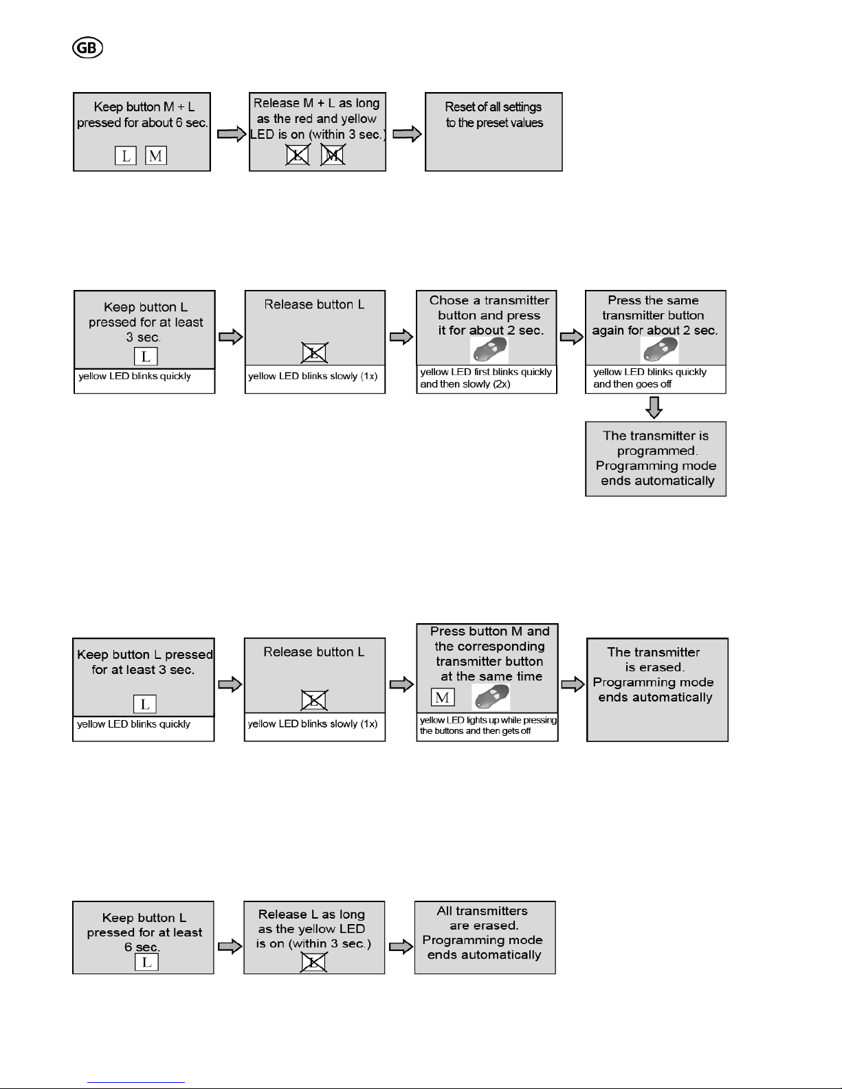
Hint:
- At first set-up of the opener (or after re-setting to the preset values) the opener switches automatically into
the programming mode.
- If accidentally the end position got overstepped during the programming mode you have got the possibility
to reverse the path direction by carrying out the following steps
Press button S and keep pressed
Press button L additionally
If there is no door reaction: pull mains plug and reconnect after approx. 1 min, then start programming once more!
ATTENTION: DANGER: During the automatic path programming of the opener the safety reversing
function or safety devices are not activated and the light is switched off!!

S 201 01-07
11
Adjustment of the single functions
HINT:
- During the programming mode LED red and yellow are blinking rotationally and indicate the chosen menu point
(numbers of blinking signals red LED) and the adjusted status (numbers of blinking signal of yellow LED).
S 201 01-07
12
Re-setting to preset values (path and force as well)
---------------------------------------------------------------------
Programming of the transmitter (only for radio system PICO 868,5 MHz, if you install a different radio system
please follow the instructions of the radio system manual).
Repeat the "Programming of the transmitter" with additional PICO transmitter.
----------------------------------------------------------------------
Erasure of a single transmitter (only for radio system PICO 868,5 MHz, if you install a different radio system please
follow the instructions of the radio system manual).
----------------------------------------------------------------------
Erasure of all transmitters (only for radio system PICO 868,5 MHz, if you install a different radio system please
follow the instructions of the radio system manual).

S 201 01-07
13
Readjustment of the force via the digital potentiometer
With the help of the digital potentiometer (preset value: middle position) the force at the door border can be adjusted to a
certain degree. Press button of the digital potentiometer for 2-3sec untill all Poti-LEDs light up. Then release the button, the
set value is shown. By pressing the button the value of power is increased, this is shown by LEDs lighting up. The power
value is increased clockwise. After reaching the maximal value, the digital potentiometer jumps back to minimum with the
next pressing of the button. After approx. 2 min. the digital potentiometer switches into a non-active mode, thereby the last
set value will be stored. In the factory set up mode and after programming of path and force the digital potentiometer is al-
ways set in the middle position! After adjusting the digital potentiometer check the cut-off force.
ATTENTION: The force values according to the norms may not be exceeded!
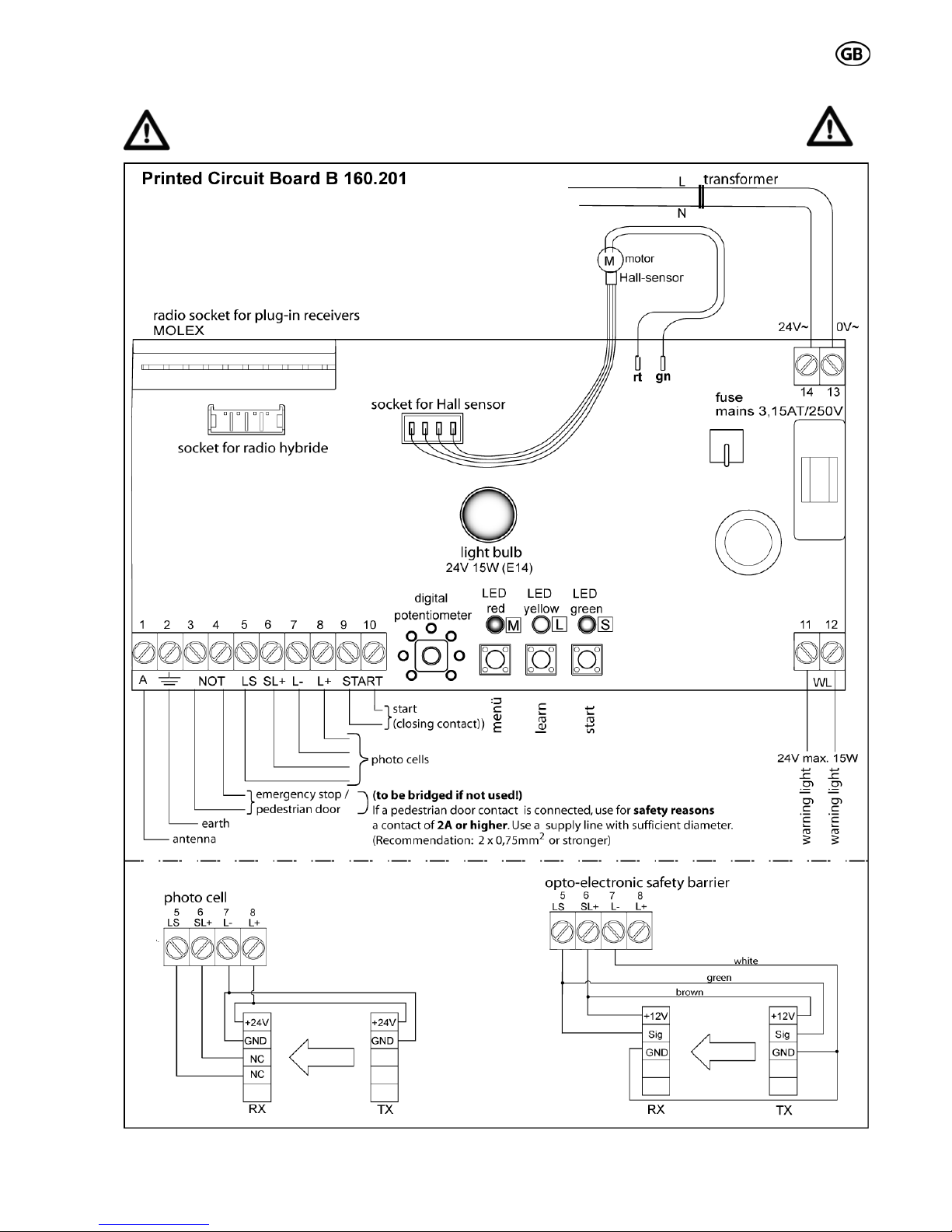
Status display / Error display:
indication red
LED (in normal
operation)
potential cause trouble shooting
continuous light emergency-stop has been activated or
jumper is missing on "NOT" terminal
eliminate the interruption, a start command will
start the operator again
1x flashing safety devices (photo cells or optoelektronic
safety barrier) have been actuated resp. are
not correctly activated
eliminate the interruption, a start command will
start the operator again
2x flashing force cut-off / overload try to start the operator again, otherwise repeat
the path and force setting
3x flashing
sensor error, the Hall-sensor cable is not or
not correctly connected or the motor cables
are interchanged
connect the Hall-sensor-cable and motor ca-
bles properly, disconnect and reconnect the
mains plug*, afterwards repeat the path and
force setting
4x flashing error on the control board will work after disconnecting and reconnecting
the mains plug*, otherwise replace control
board
5x flashing motor error, motor cables not connected connect motor cables, then disconnect and
reconnect the mains plug*
6x flashing EEPROM-data error will work after disconnecting and reconnecting
the mains plug*, if error occurs again replace
control board
indication green
LED display of operation status trouble shooting
on control unit is ready for operation
off no power supply check conduction line and fuse
*keep mains plug for 1min unplugged
S 201 01-07
14
A
TTENTION
SAFETY CHECK
Before termination of the start up you need to
do a safety check to see if the opener stops
and reverses correctly according to the EU
norms (EN 12453) when hitting an obstacle (max. force
= 150 N which corresponds to 15 kg, above an opening
of 50 mm). This check is necessary for security of
persons and objects. This security check and force
measurement may only be done by a professional. At
obstacle detection the door has to stop and reverse. If
the door does not run the desired path or if the door
does not reverse at obstacle detection, the force and
path programming procedure needs to be repeated. If
the force level at cut-off is either too low or too high,
you have to adjust the force accordingly via the digital
potentiometer. Then repeat the test.
If after these corrections the door still does not stop
and reverse according to the valid norms, the door
may not be operated with the garage door opener.
WARNINGS!
Please attach warnings visibly and close to the opener.
Maintenance
We recommend double check of the complete plant (door +
opener) by a professional once a year. Force cut-off, con-
nected safety devices and function of the mechanical
emergency lock need to be checked every 4 weeks. Even-
tually occurred errors must be corrected immediately by a
professional.
You can test the force cutoff by putting a piece of
wood (of min. 5 cm height) on the ground in the travel
range of the door (Fig. 27) and then close the door with
the GDO. When hitting the obstacle the door has to
stop and reverse.
Please only use max. 24V/15W (E14) light bulbs for
replacement purposes.
Batteries and light bulbs do not fall under warranty.
Dismounting and disposal
At dismounting and disposal the according local safety
and disposal regulations are to be followed.
Disconnect the operator before
opening the housing 230V ~!!!
and remove the light bulb.
S 201 01-07
15
Error analysis
Lighting:
• Light bulb defect:
Replace by a 24V/15W (E14) light bulb
• Opener does not have power supply:
Check mains supply lines and fuses and replace if
necessary
Radio system:
• Door does not react to transmitter signal:
Check battery and replace it if necessary.
Receiver did not learn / accept transmitter code;
repeat programming.
• Unsatisfactory transmission range:
Check connection and placement of the antenna
and correct if necessary.
Check battery output and replace it if necessary.
Use a rod antenna
Logic board:
• Door does not move at all:
Check if the inputs for safety device connection
(NOT)are bridged, or if safety devices are con-
nected
• Door only reacts on signal of a push button:
Check placement of the radio receiver and correct
if necessary
• Door stops during the movement:
Door is rough running, check door mechanic and
correct it (only by a professional!!)
• Door reverses during the movement:
Check if there is a hindrance, remove it.
Motor:
• Motor is running but the door is not moving:
Check connection of pushing rod and door and
correct it if necessary. Is the connection piece of
the chain or the belt engaged with the trolley?
• Motor runs jerkily:
Gear of the motor defect. Replace motor unit
• Motor does not start running
Check if the Hall sensor cable is connected in the
correct way (at motor and at logic board)
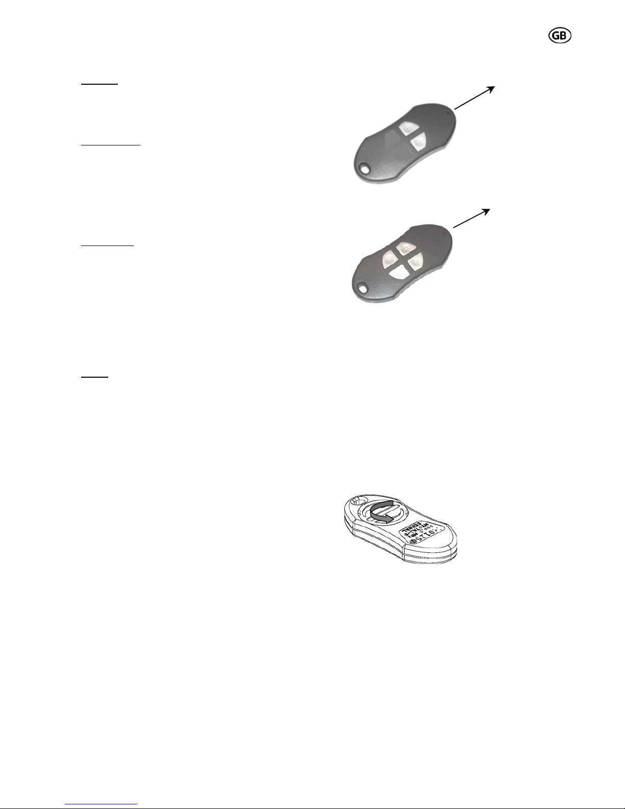
Radio system PICO, 868,5 MHz
2 channel
4 channel
Application: remote control for garage door and
gate openers
Technical data:
- Frequency 868,5 MHz
- Coding: KEELOQ®-Rolling Code System; pre-
programmed by the factory
- Each receiver has a max. capacity of 28 transmitters,
which can be programmed
- Power supply: standard 3 V lithium coin cell CR2,032
- Range approx. 50 m, depending on the surrounding field
Battery replacement:
Loosen the battery cap on the back side of the casing
by turning it to the left side (see drawing) with your
finger. Insert the new
battery with its positive
pole forward into the
battery cap. Turn the
battery cap together with
the battery back into the
casing.
IMPORTANT: Do not throw used batteries into domestic
waste; dispose them through battery recycling system!
Transmitter types:
2 and 4 channel
Conformity:
The radio system conforms to the standards of EN300,220-
3 V1.1.1; EN301,489-3 V1.4.1; EN60,335-1; EN50,371 and
may be put in circulation without additional registration in
the countries of the EU and in Switzerland.
HomeLink®-compatible:
The transmitter can also be programmed into HomeLink®-
systems of motor vehicles. Precondition is the relative
actual software state of the system integrated (beginning
with version 8).
Transmitting
direction
T1
T2
Transmitting
direction
T1
T2
T3
T4

S 201 01-07
16
Conformity
This manual suits for next models
1
Table of contents
Other Bernal Garage Door Opener manuals


Popular Garage Door Opener manuals by other brands

Chamberlain
Chamberlain Whisper Drive Security+ 182671 owner's manual

Chamberlain
Chamberlain Power Drive Assembly & installation manual

CAME
CAME EMEGA STANDARD INSTALLATION

Chamberlain
Chamberlain LiftMaster 335LM Security+ owner's manual

Novoferm
Novoferm N-423 manual

Wayne-Dalton
Wayne-Dalton 9100 Installation instruction and owenrs manual


