Bernal Sensor-Line S 401 User manual
Instruction manual
Sensor-Line S 401
Please keep this manual in a safe place.
S 401 GB - 1 - 03-06
G
B
B 190.028-GB

S 401 GB - 2 - 03-06
Index
1.0 Technical Data .................................................................................................... 3
2.0 General Instructions........................................................................................... 4
2.1 General safety instructions................................................................................ 4
2.2 Designated use................................................................................................. 4
2.3 Indication for operating...................................................................................... 4
3.0 Drive assembly ................................................................................................... 6
3.1 Scope of supply................................................................................................. 6
3.2 Required tools ..................................................................................................... 6
3.3 Installation requirements....................................................................................... 6
3.4 Assembly ............................................................................................................ 7
3.5 Installation......................................................................................................... 9
3.6 Initial operation................................................................................................ 13
3.6.1 Insert red/green light module.................................................................... 13
3.6.2 Functions and connections....................................................................... 14
3.6.3 Set-Up...................................................................................................... 15
3.6.3.1 Adjustment of force and travel ........................................................................15
3.6.3.2 Individual adjustments.....................................................................................15
3.6.4 Perform safety check................................................................................ 18
3.6.5 Warning notices........................................................................................ 18
3.6.6 Radio........................................................................................................ 18
3.6.6.1 Installation of the radio....................................................................................18
3.6.6.2 Set-Up of the radio.........................................................................................18
3.6.6.3 Testing the radio .............................................................................................18
4.0 Maintenance...................................................................................................... 19
5.0 Demounting and disposal................................................................................ 19
6.0 Failure analysis................................................................................................. 20
7.0 Operating Instructions radio system PICO, 868,5 MHz................................. 21
8.0 TÜV-Certificate.................................................................................................. 22
9.0 TÜV-Doors......................................................................................................... 22
10.0 EC-Manufacturer's Declaration ..................................................................... 23
11.0 EC- Manufacturer’s Declaration according to EC Directive........................ 24
12.0 Handing over................................................................................................... 24

S 401 GB - 3 - 03-06
1.0 Technical Data
Description S 401-60 S 401-80 S 401-100 S 401-120
standard circuit
board B 300.01
head
variations
optional red /
green light mod-
ule (red / green
light red/ green,
230VAC, 50Hz,
1A)
B 300.04
electric supply 230 V / 50 Hz
temporary peak load max. 600 N max. 800 N max. 1000 N max. 1200 N
motor voltage
circuit board voltage 0 – 24 VDC
motor power max. 110 W max. 120 W max. 150 W max. 180 W
tractive- /pressure power max. 600 N max. 800 N max. 1000 N max. 1200 N
switch-on-time 30%
speed (without load) max. 14cm/sec
lighting 40W/230V (E14)
duration of lighting 30-180 sec
Radio (standard delivery) 868,5 MHz
ambient temperature -20°C/ +40°C
idle running – power loss < 1 W
fusible cut-out F1:3,15AT/250V
F2:6,3AT/250V F1:3,15AT/250V
F2:6,3AT/250V F1:3,15AT/250V
F2:10AT/250V F1:3,15AT/250V
F2:10 AT/250V
minimum mounting height 35 mm
overall drive length 3,31 m
head height 145 mm
ca. weight (with 3,00m rail) ca. 18 kg
travel path (with 3,00m rail) 2,40 m (with extension up to 5,4 m possible)
max. area of door (smooth
running, good balanced doors) 8 m² 10 m² 12 m² 14 m²

S 401 GB - 4 - 03-06
2.0 General Instructions
This instruction manual is being released by
BERNAL without any warranty.
BERNAL reserves the right to make changes
or modifications on the equipment at any time
and on this manual without giving any prior
notes.
2.1 General safety instructions
Important Safety Instructions:
Qualified personnel should only
perform the assembly and installa-
tion of the garage door opener.
Faulty installation may lead to serious inju-
ries! Disconnect power plug before any
work on the device is done. (except on test
and learning procedures) !
On installation the relevant regula-
tions for the operational safety act
/ employers mutual insurance as-
sociation have to be followed, e.g. UVV, DIN
EN 60335-1 and VBG4.
The electro installation has to be
performed by a qualified electri-
cian, and has to conform to the
relevant industrial safety regulations, ac-
cording to DIN VDE 0100 and DIN VDE 0113.
The power point must be easily accessible
and at a max. distance of 50cm from the
opener head.
Do not operate the garage door
opener at all, until it is confirmed,
that the garage door is in accor-
dance with the safety norm 98/37/EG and a
valid EC-Declaration of Conformity certifi-
cate is issued.
.
An improper installation or any change to the
opener without the manufacturers previous
approval, any warranty or product liability is
null and void. The installation has to be per-
formed in accordance with this instruction. The
installation of foreign elements endangers the
safe operation of the opener and is not permit-
ted.
You have to pay attention that the relevant na-
tional VDE-regulations for operating electrical
appliances are strictly adhered to.
We do not take any responsibility for the im-
proper operating or maintenance of the door,
accessories and the opener.
2.2 Designated use
The garage door opener is designed only for
the operation with well-balanced swing- and
sectional doors in the non-commercial sector.
The recommended max. door measurements
are listed under 1. Technical Data. The door
has to be in accordance with the valid specifi-
cations (e.g. DIN EN 12604 and DIN EN
12605). Before mounting the opener, check
that the door can to be easily moved by hand.
FOR THE SAFETY AND LIFE OF PER-
SONS IT IS ABSOLUTELY NECESSAR
Y
TO FOLLOW ALL INSTRUCTIONS.
KEEP THESE INSTRUCTIONS
The opener is designed for the operation in dry
rooms.
The garage ceiling has to be constructed, so
that a safe attachment of the opener is as-
sured.
2.3 Indication for operating
For garages without a second entrance, a
emergency release is necessary. A function
test of the emergency release has to be car-
ried out monthly!
Do not hang on the cord of the emergency re-
lease with your weight!
Make sure, that the emergency release of the
opener does not collide with the roof rack or
any protrusions of the vehicle or the door.
Instruct all persons, who are using the ga-
rage door and opener, about a safe and
proper handling. Demonstrate and test the
reversion (with a 50 mm high obstacle at
max. 150 N) as well as the mechanical
unlocking.
Operate the door only, when you can see
the whole door area unobstructed. Pay at-
tention, that there are no persons or any
objects in the door operating area.
Wait until the door stands still. Persons or
vehicles are only allowed in door operating
area, when the door is completely open and
at standstill.

S 401 GB - 5 - 03-06
oor, opener and extra installed safety ac-
ttention: an shut down faster with weak,
hen service- or adjustment work is ur-
Do not permit children to
play with the automated ga-
rage door. Transmitters are
to be kept safe and away
from children !
Fixed accessories (like key switch or simi-
lar) have to be attached in sight of the door.
The accessory distance to the moving parts
of the door, and at a minimum mounting
height of 1,80m. Accessories have to be in-
stalled beyond the reach of children! Alert
stickers against pen in have to be put close
to the fixed key switch.
D
cessories have to be checked regularly.
See chapter 4 maintenance.
A
The door c
broken or damaged springs or a defective
counterweight. Under this circumstances
using the emergency release may lead to
uncontrolled movements of the door.
W
gently required, do not use the opener . A
badly balanced door, or a faulty garage
door drive may cause damage and injuries.
S 401 GB - 6 - 03-06
3.0 Drive assembly
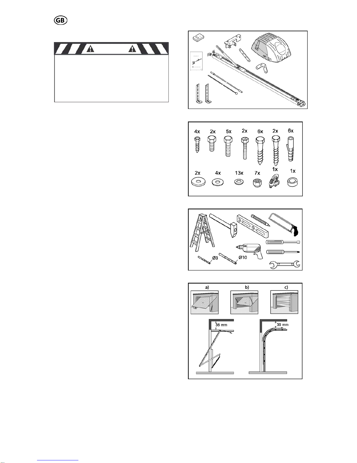
3.1 Scope of supply
The scope of supply, as shown on the Fig. 1
and 2, may vary according to the drive ver-
sion.
3.2 Required tools
For the assembly und mounting of the drive
the tools shown in Fig. 3 are required (not in
the scope of supply).
3.3 Installation requirements
The garage door opener is suitable for the
automation of spring balanced swing doors
(Fig. 4a) and sectional door (Fig. 4c).
(max. sizes see 1.0 technical data).
For an optimal attachment of the push rod to
the sectional door, a sectional door attachment
is available as an accessory.
For doors, that are non-protruding up-and-
over, a curved arm is available as accessory.
(Fig. 4b)
For the mounting a minimum lintel height of 35
mm is necessary (Fig. 4).
Fig.1
CAUTION
IMPORTANT INSTRUCTIONS FOR A
SAFE MOUNTING
ATTENTION – INCORRECT MOUNTING
MAY LEAD TO SERIOUS INJURY – ALL
MOUNTING INSTRUCTIONS HAVE TO
BE FOLLOWED
Fig. 2
Fig. 3
Fig. 4
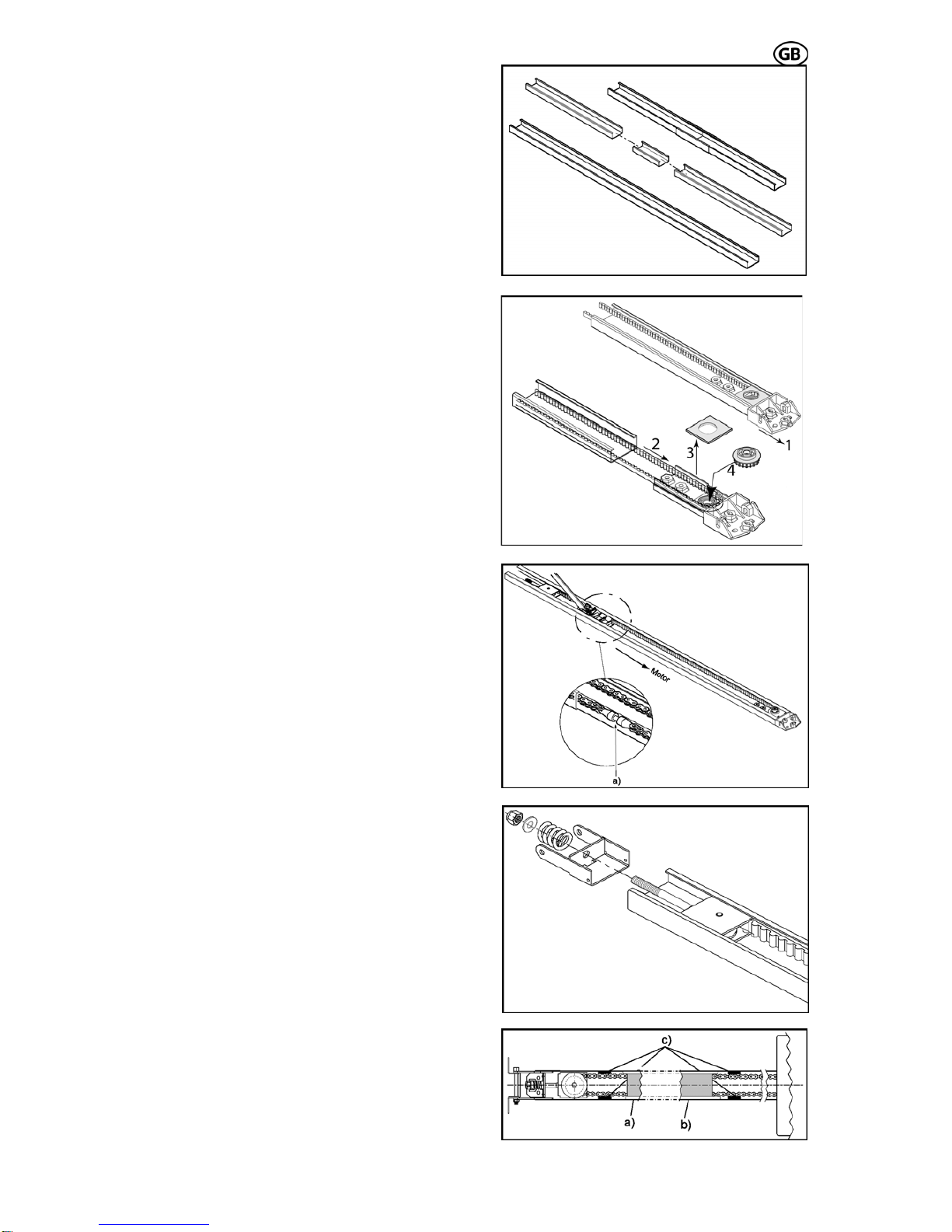
3.4 Assembly
Pre-assembly of rail
According to the version, the rails have to be
pre-mounted as requirements.
Put the rails together via the connection rail.
(Fig. 5) Slide the rails together to the stop posi-
tion.
Pull the rear bracket (Fig. 6.1) together with the
belt (Fig. 6.2) out of the rail. Remove the
transportation covering (Fig. 6.3) and press the
pinion (Fig. 6.4) into the bearing. Take care of
the belt not being squeezed. Then attach the
transportation covering again and push the
complete rear bracket back into the rail.
S 401 GB - 7 - 03-06
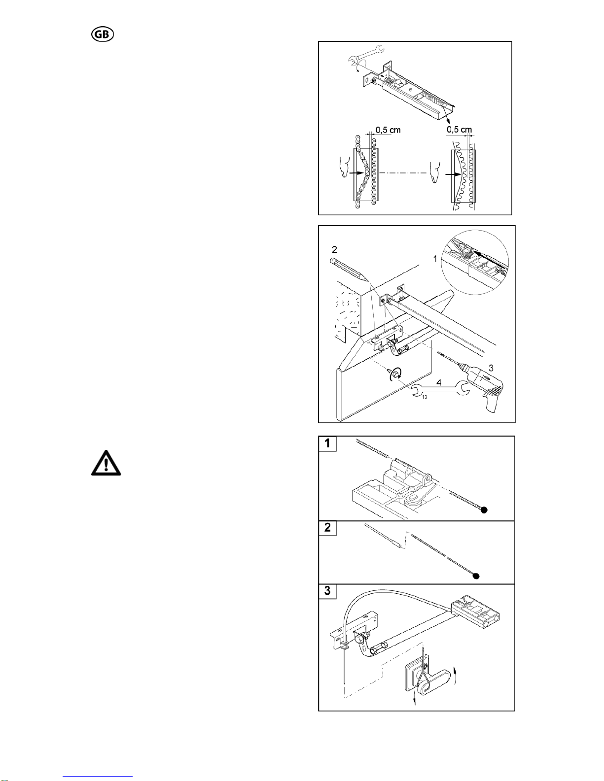
Adjust the tension of the chain or belt by pull-
ing the idler wheel towards the chain end.
Make sure, that the chain lock (Fig. 7a) is on
the left side of the rail. (Fig. 7)
Then push the tensioning bracket towards the
end of the chain and guide the coach bolt
through the hole of the tensioning bracket. Pay
attention that the coach bolt fits into the ten-
sioning bracket.
Push the provided spring and washer on the
end of the coach bolt and screw the nut on the
coach bolt. (Fig. 8)
Paste rubber buffers
If you have a chain drive, we recommend stick-
ing the provided rubber buffers to the inside of
the rail (Fig. 9c). Those serve to minimize the
noise caused, when the chain touches the rail.
Assure, that the rubber buffers are not in the
travel path of the trolley. The buffers have to
be put close to the end of the chain, so that the
trolley doesn’t touch them in door-closed- (Fig.
9a) or in door-open-position (Fig. 9b).
Fig. 5
Fig. 6
Fig. 7
Fig. 8
Fig. 9
S 401 GB - 8 - 03-06
S 401 GB - 8 - 03-06
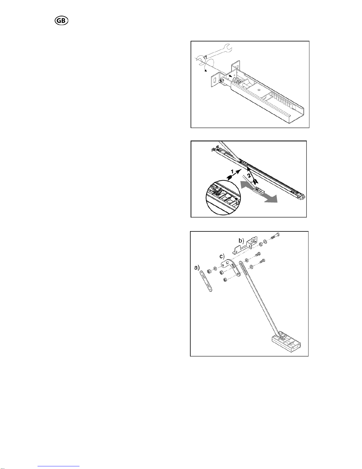
sion chain / belt
Turn the nut to tension the chain or belt
slightly. Fig. 10).
Trolley test
Check afterwards, that the trolley can easily be
moved by hand. To release the trolley, from
the chain lock, pushes the lever on the trolley
and at the same time move the trolley in the
rail (Fig. 11).
Make absolutely sure, that after this test the
trolley engages on the chain lock. To perform
this, move the trolley without holding the lever
over the chain/belt lock and the trolley en-
gages automatically.
Assembly of door bracket
According to the installation situation the pro-
vided push rod components can be combined
as needed (Fig. 12).
If the length of the push rod is not sufficient, it
can be adjusted via the extension rod (Fig.
12a). In adoption with sectional doors, we rec-
ommend the use of a sectional door angle
(Fig. 12c). Then the provided door bracket
(Fig. 12b) has to be attached to the push rod.
For the assembly use the provided screws,
washers and nuts, and tighten them firmly.
Fig. 10
Pre-ten
Fig. 11
Fig. 12

S 401 GB - 9 - 03-06
3.5 Installation
Mark the middle of the door
Measure the width of the door and mark the
iddle of the door at the lintel. (Fig. 13)
alculation of the necessary height
est door point (Fig. 14.1)
he angle a(Fig. 15) may not exceed 30°; o-
se a correct transmission of the power is
ot guaranteed.
he distance between the lower edge of the
il and the upper edge of the garage door
hould be between 5 and 7 cm in closed condi-
on.
m
C
The rail has to be mounted on such a height,
that between the high
(the highest point that the door can reach dur-
ing the movement) and the lower edge of the
rail, a clearance of at least 10-20 mm is avail-
able (Fig. 14.2).
Pay attention, that the rail is always mounted
at a level position.
T
therwi
n
T
ra
s
ti
Fig. 13
Fig. 14
Fig. 15
talling the drive all mechani-Before ins
cal locks of the door have to be put out
of order!
CAUTION

S 401 GB - 10 - 03-06
bracket
xtend the door measurements on the lintel,
so that the provid 16) is
exactly in the middle of the door and above the
required highest door position.
Us
lin
Attention:
Then attach the lintel bracket (Fig. 17) to the
lintel. (depending on the installation situation
e provided fastening screws have to be re-
laced by others).
hen fasten the rail to the lintel bracket with a
oach bolt and a lock nut (Fig. 18).
Mounting the lintel
Eed head bracket (Fig.
e a pen and mark the bracket holes on the
tel and drill the required holes (Fig. 16).
When drilling, cover the drive!
th
p
Attaching the rail to the head bracket
T
c
Fig. 16
Fig. 17
Fig. 18

Fixing of the retaining angle
S 401 GB - 11 - 03-06
g
e
(Fig. 19).
fterwards mark the points where the retaining
e
r
oles and affix the retaining
ngles to the ceiling (Fig. 20.1).
ttention: When drilling, cover the drive!
ttachment of the drive head
d shaft
n the collet of the return head (Fig. 20.2).
shown in Fig. 20.3 the drive head has to be
ttached with the 2 Phillips-screws and spring
ashers to the return head.
Bring the rail in a level position, fit the retainin
angles to the return head. Make sure, that th
rail is in a level position. The excess lengths of
the angles have to be sawed off
Attachment of the rail
A
angles shall be attached to the ceiling. Mak
sure, that the rail is aligned with the earlie
marked middle of the door.
Drill the required h
a
A
A
The next step is to insert the drive hea
o
As
a
w
Fig. 19
Abb. 20.1-20.3
- 12 - 03-06
belt
l the
hain or belt can be pushed together to
in the middle of the
il.
trolley, (Fig. 22.1)
or, where the
rill the required holes at the door and attach
, firmly to the
oor (Fig. 22.3 + 22.4).
se of an emer-
ency the door can be opened from outside.
he Bowden cable has to be moved through
e eye of the „key shaft“ and the mantle.
ig. 23.1 + 23.2) Afterwards the linkage has to
e moved through the door bracket (Fig. 23.2).
t the end of the installation of the Bowden
able has to be attached at the door handle
ig. 23.3).
is absolutely necessary, to check the correct
nction of the emergency release, before us-
g the garage door opener.
Before operating the garage door
opener: unlock the trolley and
open and close the door to the full
top by hand.
he trolley has to come to a full stop, be-
re bumping the drive head or the return
uide assembly, with the door in open /
losed position.
Adjust the tension of chain or
Turn the nut of the tension unit (Fig. 21), so
that the spring is completely compressed.
Than release the tension of the spring by turn-
ing the nut back about 1 to 2 turns, unti
c
approx. 0,5 cm distance
ra
Attachment of the door bracket assembly
First press the lever on the
and move the trolley towards the lintel.
Then mark the points of the do
door bracket shall be attached (Fig. 22.2).
D
S 401 GB
the door bracket, with 2 screws
d
Installing the emergency release
If the garage is without a second entrance, the
installation of a emergency release set is abso-
lutely necessary, so that in ca
g
T
th
(F
b
A
c
(F
It
fu
in
s
T
fo
g
c
Fig. 21
Fig. 22
Fig. 23

S 401 GB - 13 - 03-06
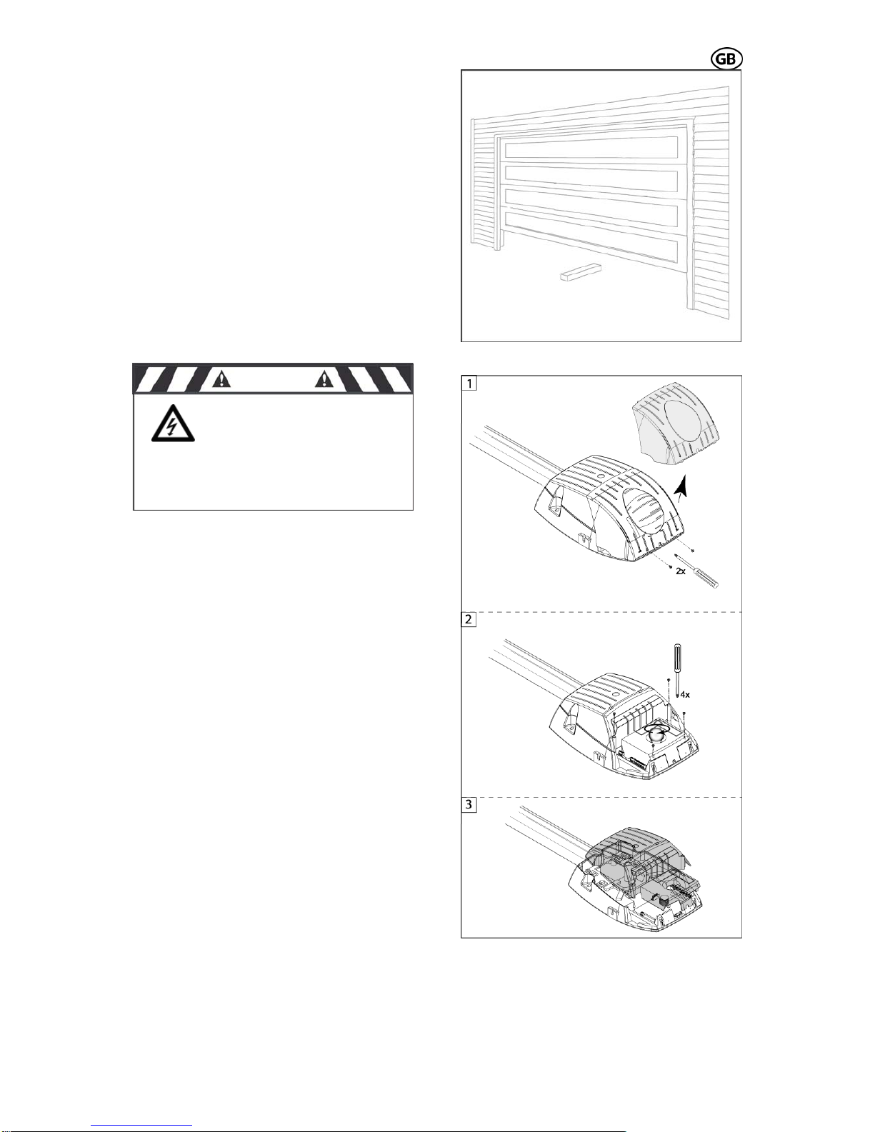
.6 Initial operation3
3.6.1 Insert red/green light module
If you want to insert the red/green light module,
you have to do the following steps:
At first, the 2 safety screws have to be re-
moved as shown in Fig. 24.1 and the light
screws of
cover has to be taken off.
Then turn out the light bulb and the 4
the cover (Fig. 24.2).
Now the cover can be taken off (Fig. 24.3) and
the red/green light module can be inserted
(correct position see Fig. 25 circuit board lay-
out).
The red/green light module has to be attached
with the provided screws on the circuit board,
and the heads of the screws have to be iso-
lated with the provided plastic covers (Fig.
24.4).
Then break out the pre-punched notch for the
red/green light module in the cover and reas-
semble the cover – screws – light bulb and
ght cover. Now plli ug the opener to the mains.
Abb. 24.1-24.4
CAUTION
Before removing the
light cover - disconnect the
power plug! 230V ~
CAUTION
The heads of the
screws must be isolated with the
ti
unde
plas c covers. The screws are
r 230 V mains voltage!

S 401 GB - 14 - 03-06
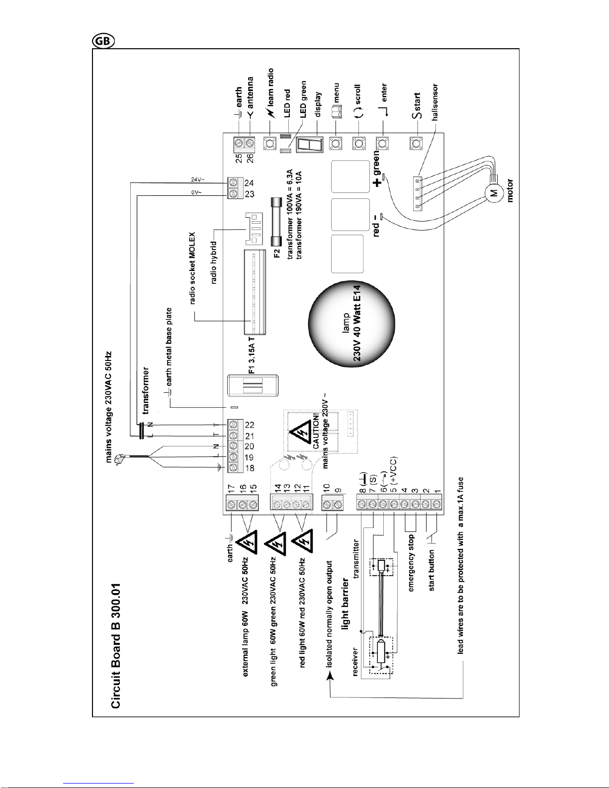
connections
e
hown in Fig. 25. For the activation and set-up
to be
nted.
The standard circuit board B 300.01 has the
follo
tion
Sta
term
The board, the start
button external and the radio receiver have the
ame function during operation (exception:
drive
oor
art button activates
the
g
mergency stop during door open move-
s to be applied. The connection ca-
le has to be laid fail safe. (e.g. with cable
type: ÖLFLEX-CLASSIC-100 2x,5mm²).
Light barrier with integra heck accord-
ing to safet
tr
te
te
re
te
terminal 7 (S): signal
rminal 8 (-): earth
sub point 4 has to be set on 1 (= active).
he receiver is always connected to the mains
ltage.
he transmitter is only active when the drive is
orking. When the drive is activated, the
ansmitter of the light barrier receives his volt-
ge.
he receiver is being activated via the
ansmitter diode and the signal of the light
arrier is switched on.
efore every start the function of the light bar-
er is being controlled.
there occurs an error on the light barrier,
ere is no start possible!
If the light barrier is activated during door clos-
ing, the drive stops and reverses (completely
or partially, according to the setting on the cir-
cuit board, menu point b1).
If there is an activation while the door opens,
there is no reaction.
CAUTION:
3.6.2 Functions and
The assembly as well as the connection- and
adjustment possibilities of the circuit board ar
s
of some connections (for example, light barrier,
safety edge, etc.) some individual adjustments
s described in paragraph 3.6.3 have
a
impleme
wing connection possibilities and func-
s:
rt button external terminal 1 (earth) and
inal 2 (signal)
start button on the circuit
s
learn function). With the start button the
can be started and stopped. During d
movement, pressing the st
the soft-stop.
Emergency stop terminal 3 and terminal 4
Wire jumper bridges terminal 3 and 4, if
emergency stop is not connected. Activatin
the e
ment, the drive is immediately stopped; when
activating while the door closes, the door stops
immediately with reversion.
If you are using a slip door, a fail safe slip door
contact ha
b
ted c
y category 2 EN 954
ansmitter:
rminal 5 (+): 80 mA / 24 V
rminal 6 (-): switched earth
ceiver:
minal 5 (+): 80 mA / 24 V
r
te
Light barrier is not connected: terminal 7 and 8
are open, Menu b sub point 4 has to be set on
0 (=inactive).When using a light barrier: menu
b
T
vo
T
w
tr
a
T
tr
b
B
ri
If
th
During the learn function, the light
barrier is not activated.
Connection safety edge 8,2 or 22 kOhm
When using a safety edge, the menu point b
sub point 5 has to be set on 1 (=active).
If there is no light barrier connected simultane-
ously (menu b sub point 4 =inactive) the safety
edge has to be just connected on terminal 7
and 8.
With an additional connected light barrier, the
safety edge has to be connected in-line with
the receiver signal of the light barrier (terminal
7) (in menu b the light barrier and the safety
edge have to be activated).
Isolated normally open output for door-
closed contact or connection warning lamp
on automatic closing terminal 9 and 10
230VAC / max 1A cos Phi = 1
30VDC/ max.1A
The external wires have to be protected with
max. 1A delay fuses.
a) Red / green light module is not installed:
When setting menu point b3 (automatic closing)
on 0 (=inactive) the clamps 9 and 10 are the
door-closed contact.
When setting b3 on 1 (=active) the terminals 9
and 10 are a isolated normally open output for a
warning lamp for automatic closing.
b) Red / green light module installed (optional)
The clamps 9 and 10 are generally door-closed
contact.
The setting of the pre-warning period automatic
closing is possible on menu point U or H (when
red / green light module is plugged).
The automatic closing period (opening period)
can be set on menu point A.
External lighting terminal 15 and terminal
16, 230 VAC/60W (max.)
t, according to the set adjust-
nu L, the internal and external
ht is on.
Connection earth terminal 17
Earth e.g. for external lighting
Connection antenna to terminal 25 and 26
To avoid interferences with the circuit board we
recommend generally: when using a pluggable
receiver (MOLEX 10-pol), connect the antenna
directly to the receiver. If this is not possible, a
rod antenna can be connected to clamps 25
and 26.
Attention: Operates only in connection with a
receiver plugged in the MOLEX-socket.
After every star
ent time at me
m
lig

S 401 GB - 15 - 03-06
iver
reaching the limit stops and breakpoints
1(PH) green : terminal 13(PH)
terminal12(N) terminal 14(N) g
returns, the pre-
Start (button on the circuit board)
1. Starting and stopping of the drive
2. Controls the drive during the learn function
(see menu).
Lighting internal 230 V / 40 W E14
Adjustment of the lighting period see menu point L.
Slot radio rece
10-pin MOLEX plug socket
Soft travel
Before
the soft travel is activated. An optimal, soft
starting and stopping of the door is achieved.
After any change in the soft travel set-up a
new power- and travel learning is necessary.
Optional module: red / green light module
terminal 11 to 14
2 relays (red, green) are provided for the red /
green light module.
red : terminal1
The pre-warning time for opening and closin
is adjustable at menu point H. At menu point b
sub point 6 red light can be switched to per-
manent lighting or blinking. After every power
failure with activated red / green light, the pre-
vious condition is being restored. At status pre-
warning, when the voltage
warning period is cancelled.
Function cycle of the red / green light control
Opening:
1. Door is closed
t blinks
ntly on (according to adjustment)
nently on
2. Start impulse
3. Pre-warning period on: red / green ligh
or is permane
4. Door opens: red light perma
5. Door is open: green light on
Closing:
1. Door is open
2. Start impulse or automatic closing
. Pre-warning period on: red / green light blinks
the menu press the
26
3
or is permanently red (according to adjustment)
4. Door closes: red light permanently on
5. Door closed: red / green light off
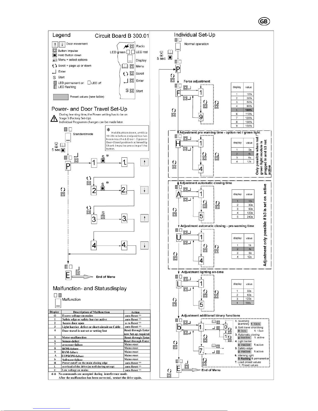
3.6.3 Set-Up
The menu structures of the different adjust-
ment possibilities are shown in Fig. 26.
Attention: After plugging the unit to the mains
wait until the green LED is permanent on, then
start set-up.
After pressing the menu button (about 5 sec.)
you get to the menu functions. With the scroll
button you can jump from one menu point or
adjustment value to the next one. When the
desired menu point or value is reached on the
display, it has to be confirmed by pressing the
nter button. For leaving
e
scroll button until it reaches the menu point E
and then confirm with the enter button.
3.6.3.1 Adjustment of force and
travel
For start-up procedure of the garage door
opener, it is absolutely necessary, to learn the
force and the travel path once (menu point P).
Follow the particular steps as shown in Fig.
(left side).
During the learning period, the end stops and
the necessary power at the different points of
door travel, are being defined by the hallsen-
sor and saved on the circuit board .
After the learning process, a test run should be
performed.
CAUTION: Make sure, that the dynamic clos-
ing power does not exceed 400N!
During the learning process, no analysis of the
light barrier and the overload is performed.
If the learning process is interrupted by emer-
gency stop, pulse length exceeding (e.g. con-
nection for pulse generator is missing) or start
button, the complete learning process has to
at can
sid
of F until the test-run is p
shu
CA
be repeated.
Manual adjustment of the power values
If you notice after the performed test run, that
the power has to be changed again, th
be adjusted at menu point F (Fig. 26, right
e). Thereby increase step by step the value
ossible without power
t off.
UTION: Make sure, that the dynamic
sing power does not exceed 40
clo 0N!
3.6
At the menu points F to b (Fig. 26, right side)
further individual adjustments can be set:
Me
at t
Me
(op ly active, if red /
e 10 sec.)
tic closure pre
menu point b3
.3.2 Individual adjustments
nu point F: Adjust the value of switch-off power
he main door closing edge (preset value 5).
nu point H: Adjust the pre-warning time,
tion) red / green light; on
green light module is installed and b3 not ac-
tive (preset value 4 sec.)
Menu point A: Adjust automatic closure pe-
riod, only possible if menu point b3 is active
(preset valu
Menu point U: Adjust automa
if
warning period , only possible
active (preset value 4 sec.)
is
Menu point L: Adjustment lighting period
(preset value 180 sec.)
Menu point b: Addititional binary functions
1. Reversion (0: full, 1: 10 cm)
2. Soft travel (0: 7 cm, 1: 15 cm)
3. Automatic closure (0: inactive,
1: active)
4. Light barrier (0: inactive 1: active)
5. Safety edge (0: inactive, 1: active)
6. Warning light (0: blinking, 1. per-
values)
manent light)
7. Load preset values (grey
S 401 GB - 16 - 03-06
Fig. 25
S 401 GB - 17 - 03-06
Fig. 26

S 401 GB - 18 - 03-06
erform safety check
For the safety of persons and ob-
jects, a safety check has to be per-
formed. Before finishing the initial op-
eration make sure that the drive stops and re-
verses according to the valid norms (EN
12453).
When reaching an obstacle (max. 150 N force
= ca. 15 kg, above an opening width of 50 mm)
the door has to stop and reverse - completely
or partial, depending on the adjustment on the
circuit board. This test and measurement of
force can only be performed by a professional.
If the door does not move the right way or
does not reverse when reaching an obstacle,
the force and travel adjustments have to be
repeated (chapter 3.6.3.1, menu point P and
Fig. 26). If the shutdown force is too low or too
high, at menu point F (chapter 3.6.3.2 and Fig.
26) the force has to be set correspondingly.
Afterwards repeat the test.
If the door, after the performed corrections
does not stop and reverse according to the
valid norms, the door may not be operated
automatically.
3.6.5 Warning notices
Warning notices against pen in have to be pla-
ced at an eye-catching place or near to the
drive (Fig. 28).
3.6.6 Radio
3.6.6.1 Installation of the radio
If your drive is not fitted with a factory equipped
radio system, the receiver has to be fitted to
the circuit board. To fit the receiver, the light
cover has to be taken off (Fig. 27.1), then plug
the receiver on the 10-pin molex socket a) as
shown in Fig. 27.2.
3.6.6.2 Set-Up of the radio
According to the radio system used, the set-up
operation of the radio can be different. For the
standard radio system PICO there is a
description in the annex of this manual.
3.6.6.3 Testing the radio
The first function test of the radio should be
performed generally inside of the garage (Fig.
29.1).
Test the radio twice inside the garage. After
successful performance, go in front of the ga-
rage and test the radio again twice (Fig. 29.2).
3
.6.4 P
Fig. 27.1-27.2
Fig. 28
Fig. 29.1-29.2
S 401 GB - 19 - 03-06
S 401 GB - 19 - 03-06
4.0 Maintenance
We recommend, that the door system be
checked once a year by a professional.
The force shutdown, possibly installed safety
equipment and the emergency release have to
be checked every 4 weeks and have any pos-
sible failures repaired immediately by an pro-
fessional.
The force shut-off can be tested, by putting a 5
cm or higher piece of wood on the floor, in the
travel path of the door (Fig. 30). Now close the
door . When reaching the obstacle, the door
has to stop and reverse (completely or par-
tially, according to the performed setting on the
circuit board).
If an exchange of single components (e.g. cir-
cuit board, motor, etc.) of the drive is neces-
sary, first remove the light cover. For that pur-
pose remove both safety screws as shown in
Fig. 31.1. After removing the light cover turn
out the bulb. Afterwards remove the 4 screws
of the cover (Fig. 31.2) and take it off (Fig.
30.3).
When exchanging the bulb, only a bulb with
max. 40 W (E14) may be used.
Batteries and bulbs are not included in war-
ranty claims.
After finishing the repairs, put back all parts in
reverse order.
5.0 Demounting and disposal
For demounting and disposal the local safety
and disposal regulations have to be followed.
Fig. 30
Fig. 31.1-31.3
CAUTION
Before taking the cover
off, disconnect the power
plug 230V ~

S 401 GB - 20 - 03-06
L g
6.0 Failure analysis
ightin :
bulb defective:
exchange with 40W/ 230V E14 bulb
• drive is without mains voltage:
• check power plug and fuses and ex-
•
change if necessary
Radio system:
• door does not run with transmitter
check the battery of the transmitter and
exchange if necessary.
receiver has not learned the code of
the transmitter, repeat learning proc-
ess.
• range is dissatisfying:
check the connection and the location
of the antenna and correct if neces-
sary.
check the output of the battery and ex-
d:
change if necessary.
use a rod aerial.
circuit boar
ly reacts with push button:
e placement of the receiver
ange if necessary.
or me-
chanic and renew if necessary (only by
• door does not move:
check, if the safety inputs are
jumpered or safety installations are in-
stalled and not connected.
• door on
check th
and exch
• door stops while travelling:
door is too tight, check the do
a professional !!)
• door reverses while moving:
check if there is an obstacle in the
travel path and remove the obstacle.
motor: motor runs, but the door does not
check the connection between push
motor gearbox defective, exchange
the circuit board):
• move:
rod and door and correct if necessary,
check if the trolley is engaged in the
chain/belt lock?
• motor jerks:
complete motor unit
• motor does not start
• check, if the hallsensor cable is con-
nected correctly (at the motor and at
Table of contents
Other Bernal Garage Door Opener manuals


