Bernard Burton Spirit of Pitts User manual

© 2005 - Bernard Burton DRAFT 1
Designed in 2005
by Bernard Burton
Assembly manual

© 2005 - Bernard Burton DRAFT 2
The plans can be requested via this link http://www.gundersonaerodesign.com/m12plansreq.htm
The laser kit is available here http://www.gundersonaerodesign.com/ . Gunderson AeroDesign is a
company located in Vista, CA dedicated to the radio controlled aircraft hobby.
Note
This assembly manual is not intended to tell you how to build this aircraft, each builder has their own approach to building. This is only a guide
which will show you how we built our Spirit of Pitts. Use it if you feel that it may help.
NOT ALL STEPS ARE SHOWN IN THIS MANUAL.
Disclaimer
This plane and plans are intended for ADVANCED BUILDERS and PILOTS ONLY !
The user shall determine the suitability of the product for their intended use, and shall assume all risk and liability in connection therewith. The
builder assumes all risk of injury when building this plane.

© 2005 - Bernard Burton DRAFT 3
Fuse:
Step 1: Prepare the fuse sides S1.
- Glue the 3 fuse side sections together. Use a long straight edge to assure alignment
along top edge.
- Glue the front side doubler S2 on S1 with 30’ epoxy and let the epoxy cure.
Step 2: Glue the former doubler F2a on F2 with 30’ epoxy. The second F2 former does not
require to be doubled. Let the epoxy cure.
Î
Step 3: Build crutch assembly, upside down, on a flat workbench. We can not emphasize enough
the importance of building this crutch square and also the alignment to the print. (This is
as important as building a straight wing). The flat surface of the formers should be placed
on the workbench.
Glue with 30’ epoxy the formers F5, F2, F2’ (doubled), F3 and F4 on their respective
places on the fuse sides S1. Be sure your start with F5 first. Verify and eventually adjust
the alignments and let the epoxy cure.
Note: Be sure that you prepare one right side and one left side.

© 2005 - Bernard Burton DRAFT 4
Step 4: Glue F1 and then C1 in place. Before the 30’ epoxy cures, glue C3 (fuse front bottom)
and C2 (fuse front top) on their place. Verify and eventually adjust the alignments and let
the epoxy cure.
Step 5: Glue the S1 doublers between F1 & F2 and between F2’ and F3 on the outsides of F1.
This is to re-enforce the position where the wing struts are attached.
Step 6: Glue F6, F7, F8 and F9 in place. Verify and eventually adjust the alignments and let the
epoxy cure.
Step 7: Join the formers with balsa sticks:
Helpful hint: Use a piece of scrap foam or balsa to hold the fuse sides out against
the formers while you glue the formers in place.

© 2005 - Bernard Burton DRAFT 5
- Glue two 10x10 mm Balsa sticks on the lower right and left former slots from F1 up to
F9
- Glue two 10x10 mm Balsa sticks on the upper right and left former slots from F1 up to
F9
- Glue one 10x10 mm Balsa stick on the top former slots from F6 up to 3 cm behind F8
- Glue one 10x10 mm Balsa stick on the bottom former slots from F5 up to F9
- Glue one 10x10 mm Balsa stick on the bottom former slots from F2 up to F2’
- Glue four 5x5 mm Balsa sticks on the top former slots from F6 up to the end of the
fuse (F9)
- Glue four 5x5 mm Balsa sticks on the former slots (top half) from F6 up to the end of
the fuse
- Glue four 5x5 mm Balsa sticks on the former slots (bottom half) from F5 up to the
end of the fuse (F9)
- Glue four 5x5 mm Balsa stick on the former slots (bottom half) from F2 up to F2’
Step 8: Prepare the removable canopy:
- Put the canopy formers FT1, FT2, FT3, FT4 and F6a on their place according the
plans on the fuse. Do not glue the formers on the fuse.
- Glue the 5x5 mm & 10x10 mm balsa sticks on the formers according the plan. Pay
attention that the lower 10x10 mm stick is going up to F6a. Do not glue the stick on
the fuse.
- Glue A1 and A2 onto the 10x10 sticks according the plan and glue the 5x5 mm sticks
between the formers
- Cover with 2 mm balsa sheet according the plan drawings
- If you have a Fiberglass or Carbon canopy then glue it on its place on the removable
canopy frame.
-
Step 9: Finalize the fuse structure:
- Glue the rear landing gear re-enforcement at the bottom of the fuse sides on the
back-end of the fuse
- Glue F9 (wing fuse fixation) in place with 30’ epoxy. Re-enforce with triangular balsa
on the inside and outside of the fuse sides.

© 2005 - Bernard Burton DRAFT 6
Step 10: Prepare the landing gear cover:
- Glue the F1a formers together via 10x10 mm and 5x5 mm sticks
- Cover with 2 mm balsa sheet.
- The landing gear cover must fit in the fuse landing gear hole but should not be glued
on the fuse
- Cut the landing gear cover at the level of the fuse landing gear exit.
Step 11: Cover the fuse:
- Prepare the covering sheets by gluing the required number of 2 mm balsa sheet and
required length side by side. This operation can easily be done with CA glue when the
sheets are placed on a Wax paper.
- To allow easy sheet wrapping around the fuse, you can spread an Ammoniac-Water
mixture on the balsa sheet. Wrap the wet sheet in place and let it dry for a night
- Use CA glue to glue the balsa sheets according the plan drawings with special care
for the wing join.
Step 12: Elevator and rudder assembly:
- On a flat workbench, build the elevator and rudder panels using a copy of the plans.
Use polyurethane glue for maximal robustness.
- Use 10x10 mm hard wood for the leading edge of the fix rudder and elevator parts.
- Glue the rudder (fixed part) on the elevator (fixed part) at 90° with 30’ epoxy. Re-
enforce the glue join with triangle spars.
- We recommend using 3mm Pin-hinges for the rudder and elevator articulations.
- Check the fit on the fuse but do not glue on the fuse at this stage.

© 2005 - Bernard Burton DRAFT 7
Step 13: Prepare the motor cowl
- Prepare all the cowl concentric rings (CR1 – CR8) by gluing their sub-parts with CA
glue.
- Glue the concentric rings together as showed on the plan with 30’ epoxy. Verify and
eventually adjust the alignments and let the epoxy cure.
- Glue all the 5x5 mm sticks between the three CF rings. Verify and eventually adjust
the alignments and let the epoxy cure.
- Wrap the cowl with 2mm balsa sheet. Glue with 30’ epoxy.
- Sand the concentric rings on the outside to have a smooth & curved cowl noose
- Wait until the motor is installed before adjusting & fixing the cowl on the fuse
Helpful hint: The length of the cowl should your motor length and/or its position to
allow plane balancing

© 2005 - Bernard Burton DRAFT 8
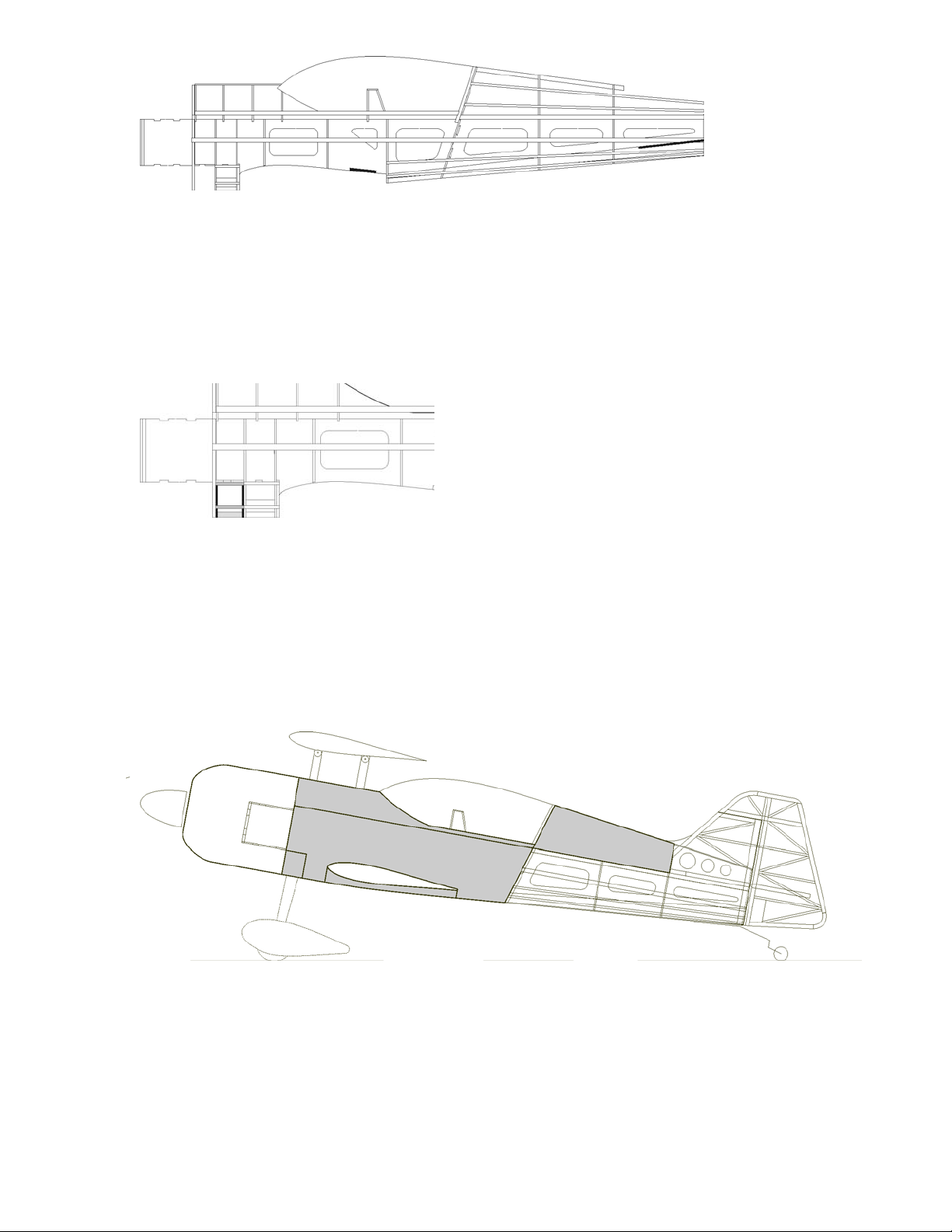
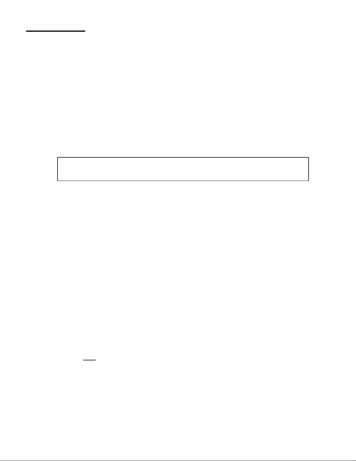
Upper wings:
Step 1: Prepare the top left wing:
- On a flat workbench, prepare & protect your plan.
- Pin the lower main spar on the plan
- Glue all the wing ribs on the lower main spar (Hard wood 10x10 mm) according the
plan. W1-W2-W3-W4-W9 should be glued with 30’ epoxy. Other ribs can be glued
with polyurethane glue. Pin the rear rib alignment tabs on the workbench to
guarantee a straight wing trailing edge
- Proceed with the upper main spar (Hard wood 10x10 mm) as well as with the top 5x5
mm balsa spars
- Glue the 10x10 mm Balsa leading edge and the balsa trailing edge
- Proceed with all remaining 5x5 mm balsa spars (upper & lower)
- To prevent wing torsion, glue 2 mm balsa re-enforcement between the upper and
lower main spars (vertical fiber direction)
- Cover the wing with 2 mm balsa sheet according the plan
- Glue the rib caps.
- Prepare the servo support assembly and glue it in place. Consider that the servo arm
is on the lower side of the wing
- Install the optional wing tip if required. Use the small balsa square triangles to re-
enforce the wing tip fixation.
- Prepare the aileron: pin a 2mm balsa sheet according the plan. Glue the aileron ribs
(small & long triangles). Re-enforce at the position of the control horn. Put the leading
edge spars (square & triangle) and cover the top with a 2 mm balsa sheet.
- Put a wire in the wing to ease the servo wires installation at a later stage.
- When the glue is fully cured, remove the wing & aileron from the workbench
- Glue W9a & W9b plywood ribs on W3 & W9 with 30’ epoxy. The tabs should be
placed on the lower side of the wing
- Remove the rib alignment tabs. Except the W1 & W9 alignment tabs.
- If your job is well done, the wing should rest on the four wing fixation tabs and stay
perfectly straight.
- Continue to cover the wing with 2 mm balsa sheet according the plan but ensure that
you can still access W1-W2-W3-W4 ribs to glue the wing tubes at a later stage.
Step 2: Prepare the top right wing following the same instructions as here above.
Step 3: When the right & left upper wings are ready, proceed as follow:
- On a flat workbench, align the wings and glue the right & left half wing tube sockets in
place with the aluminum tube inside. Do not glue the aluminum tube in their sockets.
Note: a dry assembly could be required to ensure a perfect alignment before gluing.
- Verify and eventually adjust the alignments before the glue cures
- Close the right & left wings with the remaining 2mm balsa sheeting
- Remove the remaining alignment tabs.
-
- Glue the remaining rib caps
- At this stage, the wings alignment should be perfect: straight & not twisted. The eight
wing fixations tabs should rest on the workbench without any constrains.
- Sand the leading edges.
- Your top wing is ready.
Note: During the previous steps, always verify and eventually adjust the
alignments before the glue cures.

© 2005 - Bernard Burton DRAFT 9
Bottom wings:
Step 1: 1) Prepare upper left wing:
- On a flat workbench, prepare & protect your plan.
- Pin the lower main spar on the plan
- Glue all the wing ribs on the lower main spar (Hard wood 10x10 mm) according the
plan. W1B-W2B-W3B-W9 should be glued with 30’ epoxy. Other ribs can be glued
with polyurethane glue. Pin the rear rib alignment tabs on the workbench to
guarantee a straight wing trailing edge
- Proceed with the upper main spar (Hard wood 10x10 mm) as well as with the top 5x5
mm balsa spars
- Glue the 10x10 mm Balsa leading edge and the balsa trailing edge
- Proceed with all remaining 5x5 mm balsa spars (upper & lower)
- To prevent wing torsion, glue 2 mm balsa re-enforcement between the upper and
lower main spars (vertical fiber direction)
- Cover the wing with 2 mm balsa sheet according the plan
- Glue the rib caps
- Prepare the servo support assembly and glue it in place. Consider that the servo arm
is on the lower side of the wing
- Install the optional wing tip if required. Use the small balsa square triangles to re-
enforce the wing tip fixation.
- Prepare the aileron: pin a 2mm balsa sheet according the plan. Glue the aileron ribs
(small & long triangles). Re-enforce at the position of the control horn. Put the leading
edge spars (square & triangle) and cover the top with a 2 mm balsa sheet.
- Glue W9a plywood ribs on W9 with 30’ epoxy. The tabs should be placed on the
upper side of the wing
- Put a wire in the wing to ease the servo wires installation at a later stage.
- When the glue is fully cured, remove the wing & aileron from the workbench
- Remove the rib alignment tabs except the W1b & W9 alignment tabs.
- Continue to cover the wing with 2 mm balsa sheet according the plan but ensure that
you can still access W1-W2-W3-W5 ribs to glue the wing tubes at a later stage.
Step 2: Prepare bottom right wing following the same instructions as here above.
Step 3: When the right & left bottom wings are ready, proceed as follow:
- On a flat workbench, align the wings and glue the right & left half wing tube sockets in
place with the aluminum tube inside. Do not glue the aluminum tube in their sockets.
Note: a dry assembly could be required to ensure a perfect alignment before gluing.
- Verify and eventually adjust the alignments before the glue cures
- Remove the remaining alignment tabs.
- Close the right & left wings with the remaining 2mm balsa sheeting
- Glue the remaining rib caps
- At this stage, the wings alignment should be perfect: straight & not twisted. The four
tabs (wing fixations) should rest on the workbench without any constrains.
- Sand the leading edges.
- Your bottom wing is ready.
Note: During the previous steps, always verify and eventually adjust the
alignments before the glue cures.

© 2005 - Bernard Burton DRAFT 10
Plane geometry parameters:
•Wingspan 175 cm
•Length 175 cm
•Airfoil E169 (14.5%)
•Wings surface 119 dm²
•Weight 6.5 Kg (estimated)
•Wing load 54 grs / dm² (estimated)
•Top wing incidence: 0°
•Bottom wing incidence: 0°
•Elevator incidence: 0°
•Motor down trust angle: 0°
•Motor right trust angle: 2°
Plane geometry alignment:
Step 1: Align the bottom wing:
- Put the wing in place.
- Verify and adjust the wing position:
oThe distance between the trailing wing tip and the end of fuse must be the
symmetric for left and right wings.
oThe wing horizontal axis must be perpendicular (90°) with the vertical fuse
axis.
oThe wing incidence compared to the fuse axis = 0°
oDrill the wing fixation holes in S9. Glue the screw fixing nut with 30’ epoxy.
oVerify and eventually adjust again the alignments before the glue cures.
Step 2: Align the elevator/rudder assembly:
- Fix the bottom wings with Nylon screws.
- Align the elevator/rudder assembly with the bottom wing:
oThe distance between the trailing wing tip and the trailing elevator tip must be
the symmetric for left and right.
oThe wing horizontal axis must be parallel with the elevator horizontal axis
oThe elevator incidence compared to the fuse axis = 0°
oGlue the elevator/rudder assembly with 30’ epoxy
oVerify and eventually adjust again the alignments before the glue cures.
Step 3: Align the top wing:
- Screw the wings struts on the bottom wing with 3mm screws
- When the top wing is positioned on the fuse wing struts, the holes in the wing
fixations tabs should be perfectly aligned with the fixation holes on the wing struts
without any kind of constrains. This is the demonstration that your plane is build
straight.
- Fix the top wing with 3mm screws.
oThe distance between the trailing wing tip and the end of fuse must be the
symmetric for left and right wings.
oThe wing horizontal axis must be perpendicular (90°) with the vertical fuse
axis.
oThe top wing horizontal axis must be parallel with the bottom wing horizontal
axis
oThe wing incidence compared to the fuse axis = 0°

© 2005 - Bernard Burton DRAFT 11
Center of Gravity:
The plane should be centered at 25% of the median chord or 147 mm from the leading edge of
the top wing. The Center of Gravity can be moved backward for 3D acrobatics.
Table of contents
Popular Toy manuals by other brands

Radica Games
Radica Games 20Q P6624 instruction manual

Seagull Models
Seagull Models YAKOVLEV YAK 3 ARF Assembly manual

Extreme Networks
Extreme Networks SS1-CV instruction manual

atd models
atd models ATD007 instruction manual

Velleman
Velleman KNS15 user manual

Mega Bloks
Mega Bloks Skylanders Cut Throat Carnival manual

Fisher-Price
Fisher-Price THOMAS & FRIENDS TRACK MASTER STEAMWORKS REPAIR... quick start guide

Black Horse Model
Black Horse Model GLASAIR Instruction manual book

Skysun Hobbies
Skysun Hobbies Pitts 150cc Assembly manual

Kid's CONCEPT
Kid's CONCEPT Bistro White wooden kitchen Assembly instruction

Billing Boats
Billing Boats African Queen BB588 manual

Fisher-Price
Fisher-Price FGW16 quick start guide