manuals.online logo
Brands
  1. Home
  2. •
  3. Brands
  4. •
  5. CyberData
  6. •
  7. Switch
  8. •
  9. CyberData 011187 Manual

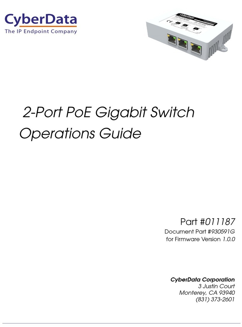
CyberData 011187 Manual

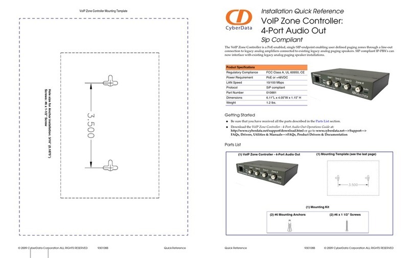
Quick Reference 930469I © 2021, CyberData Corporation, ALL RIGHTS RESERVED© 2021, CyberData Corporation, ALL RIGHTS RESERVED 930469I Quick Reference
Installation Method
The site where you install the switch may greatly affect its performance. When installing, please take the following into
consideration.
• Install the switch in a cool, dry place. See the technical specifications tab at https://www.cyberdata.net/products/011187
for the acceptable temperature and humidity operating ranges.
• Install the switch on a secure, level surface. Alternatively, the switch can be applied to any smooth dry surface using
furnished stick-on tape.
• Leave at least 10cm of space at the front and rear of the switch to ensure adequate ventilation.
Desktop or Shelf Installation
When installing the switch on a shelf on desktop, make sure that the previously mentioned guidelines in the
Installation Method section are followed for adequate ventilation.
Typical Installation
802.3af or
802.3at
PoE Power for Phone
Non-PoE
Mounting Options:
1. Mounting Screws (not included)
• Use a size 6 to 8 pan head screw.
2. Adhesive
• Peel off the adhesive backing and attach the
unit to a suitable surface.
The Standard Cable, RJ-45 Pin Assignment
The following figures shows a straight cable and a crossover cable connection. Use a straight cable connection to connect switch/
Hub or other devices:
Straight cable for the switch (uplink MDI-II port) to switch/Hub or other devices connection.
Crossover cable for switch (MDI-X port) to switch/hub or other network devices (MDI-X port) connection.
Contacting CyberData
Sales: 831-373-2601 ext. 334
Support: 831-373-2601 ext. 333
Support Website: http://support.cyberdata.net/
RMA Department: 831-373-2601 ext. 136
RMA Email: [email protected]
RMA Status: http://support.cyberdata.net/
Warranty Information: http://support.cyberdata.net/
Corporate Headquarters
CyberData Corporation
3 Justin Court
Monterey, CA 93940, USA
Phone: 831-373-2601
Fax: 831-373-4193
http://www.cyberdata.net/
The IP Endpoint Company
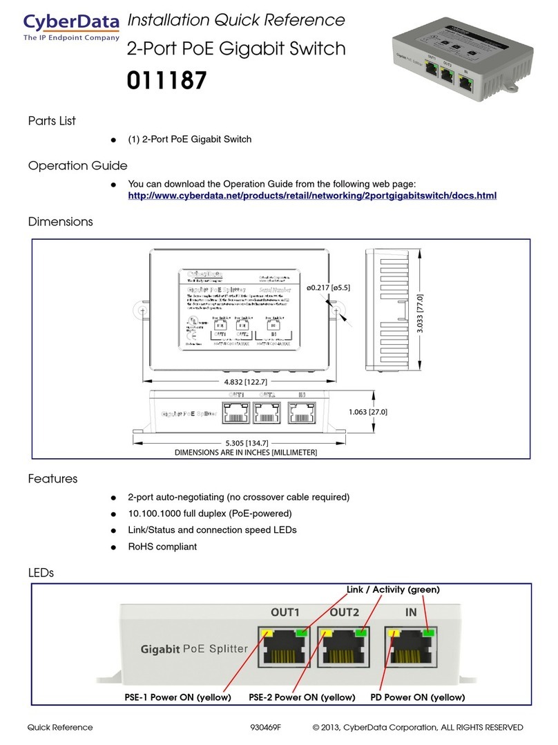
Installation Quick Reference
2-Port PoE Gigabit Switch
011187
© 2021, CyberData Corporation, ALL RIGHTS RESERVED 930469I Quick Reference Quick Reference 930469I © 2021, CyberData Corporation, ALL RIGHTS RESERVED
Network Connection
Connect your devices (computer, router, switch, IP Phone, Wireless Access Point, IP Camera, etc.) to the ports with a CAT-5/
CAT-5e/CAT-6 network cable. Since the switch supports Auto MDI/MDI-X, you can use either a straight through or cross-over
network cable.
• Connect the switch from the PD port to your central Gigabit PoE Switch.
• Connect your IP Phone to any of the of the PSE2 ports on the switch.
• Connect your computer or other networking device to any of the PSE2 ports on the switch.
The Standard RJ-45 Introduction
Regarding cable-making methods, a cable which does not meet the standards of the sequence data will make the data
transmission speed slow, unstable and even be blocked. Ta b l e 1 represents the standard RJ-45 jack and the connector
(Figure 1) and pin definition:
Figure 1. Standard RJ-45 Jack / Connector
Table 1. RJ-45 Connector Pin Definitions
Pin Number Signal
1 _TX1 +(PoE Power+)
2 _TX1 - (PoE Power+)
3 _RX1 + (PoE Power-)
4_TX2+
5_TX2--
6 _RX1 - (PoE Power-)
7_RX2+
8_RX2-
PoE Switch
Dimensions
Powering on the 2-Port PoE Gigabit Switch
The switch is powered by your existing central POE Switch. No additional power supply is required. Simply plug your cable from your
central POE switch into the PD port of the switch and your switch will power on for use.
How the Input Power is Distributed
LED Status Description
PD (Orange) ON Switch has a connection from the PD port to the PSE device.
Power has been successfully applied.
OFF Connection to the PSE device is not present.
No power has been applied to the switch.
PSE (Orange) ON PD device such as IP phone is connected to the port and
drawing power.
OFF PD device is not connected or no power is being drawn from
the switch.
Link/Act (Green) ON
A valid link
is
established.
Blink Traffic is present on port.
OFF
No
link
has been established.
4.832 [122.7]
DIMENSIONS ARE IN INCHES [MILLIMETER]
3.033 [77.0]
1.063 [27.0]
5.305 [134.7]
Ø0.217
[Ø5.5]
PSE PSE PD
CyberData Corporation
www.cyberdata.net
Link / Activity (green)
PSE-1 Power ON (yellow) PSE-2 Power ON (yellow) PD Power ON (yellow)

Other CyberData Switch manuals

CyberData External Hub User manual

CyberData

CyberData External Hub User manual

CyberData 011539 Manual

CyberData

CyberData 011539 Manual

CyberData 011528 Manual

CyberData

CyberData 011528 Manual

CyberData 011539 Manual

CyberData

CyberData 011539 Manual

CyberData 10807 User manual

CyberData

CyberData 10807 User manual

CyberData Hub User manual

CyberData

CyberData Hub User manual

CyberData 11187 User manual

CyberData

CyberData 11187 User manual

CyberData 10845 User manual

CyberData

CyberData 10845 User manual

CyberData 011508 Manual

CyberData

CyberData 011508 Manual

CyberData 10845 User manual

CyberData

CyberData 10845 User manual

CyberData 10807 User manual

CyberData

CyberData 10807 User manual

CyberData 4-Port PoweredUSB 2.0 Hub User manual

CyberData

CyberData 4-Port PoweredUSB 2.0 Hub User manual

CyberData 11006 User manual

CyberData

CyberData 11006 User manual

CyberData KS-1000 User manual

CyberData

CyberData KS-1000 User manual
CyberData RS232 User manual

CyberData

CyberData RS232 User manual

CyberData 11187 Manual

CyberData

CyberData 11187 Manual

CyberData 10807 User manual

CyberData

CyberData 10807 User manual

CyberData 10845 User manual

CyberData

CyberData 10845 User manual

CyberData 4-Port PoweredUSB 2.0 Hub 011006 User manual

CyberData

CyberData 4-Port PoweredUSB 2.0 Hub 011006 User manual

CyberData 10630 User manual

CyberData

CyberData 10630 User manual
CyberData 10630 User manual

CyberData

CyberData 10630 User manual

CyberData 011539 Manual

CyberData

CyberData 011539 Manual

CyberData 10776 User manual

CyberData

CyberData 10776 User manual
CyberData 11187 Manual

CyberData

CyberData 11187 Manual
Popular Switch manuals by other brands

soniKKs HFU-D-310 user guide

soniKKs

soniKKs HFU-D-310 user guide

Dell PowerConnect 2016 user guide

Dell

Dell PowerConnect 2016 user guide

AMX Solecis SDX-414-DX quick start guide

AMX

AMX Solecis SDX-414-DX quick start guide

Cisco Nexus 7000 Series Command reference

Cisco

Cisco Nexus 7000 Series Command reference

Nxg AB2 owner's manual

Nxg

Nxg AB2 owner's manual

Endress+Hauser Nivotester FTL 375 N 3 Series manual

Endress+Hauser

Endress+Hauser Nivotester FTL 375 N 3 Series manual

Extron electronics Converter CVC 200 user manual

Extron electronics

Extron electronics Converter CVC 200 user manual

Fore Systems forerunner series Configuration manual

Fore Systems

Fore Systems forerunner series Configuration manual

Eaton EATS16N Installation and user manual

Eaton

Eaton EATS16N Installation and user manual

Lucent Technologies 4ESS SCS Maintenance manual

Lucent Technologies

Lucent Technologies 4ESS SCS Maintenance manual

Lindy 32969 user manual

Lindy

Lindy 32969 user manual

TRENDnet TFC-1600MM user guide

TRENDnet

TRENDnet TFC-1600MM user guide

Lindy 32585 user manual

Lindy

Lindy 32585 user manual

CoCo AWMR-230 user manual

CoCo

CoCo AWMR-230 user manual

gofanco HDRswitch4P-Aud user guide

gofanco

gofanco HDRswitch4P-Aud user guide

Quintum DX Series DX8120 supplementary guide

Quintum

Quintum DX Series DX8120 supplementary guide

ABB 3299A-A02100 x Installation and usage manual

ABB

ABB 3299A-A02100 x Installation and usage manual

Ross Ultrix Carbonite Installation and cabling guide

Ross

Ross Ultrix Carbonite Installation and cabling guide

manuals.online logo
manuals.online logoBrands
  • About & Mission
  • Contact us
  • Privacy Policy
  • Terms and Conditions

Copyright 2025 Manuals.Online. All Rights Reserved.