4
one-minute warm-up and self-zeroing sequence
when it is first turned on in fresh air. The alarm of
the instrument may very loud without contact any
gas. That is caused by the high Tic Rate preset in
rotary wheel.
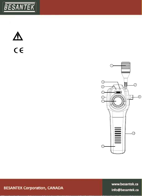
Rate (Sensitivity) Adjustment
Each time the instrument is put into service, you
should conduct a quick functional test. Adjust the
Tic Rate to non-alarm level. Then, simply expose
the sensor to a known leak, like a cigarette lighter,
or pass the probe over a drop of combustible fluid.
After the initial warm-up, the instrument can be used
to detect combustible gasses. When the sensor in
the probe tip detects a combustible gas, the tic rate
will increase and the instrument sounds a warbling
tone while the ALARM light. As the concentration of
gas increases so does the tic rate.
If the situation calls for quiet operation, or if
background noise makes it difficult to hear the
built-in speaker, you can use an earphone. The jack
is at the top of the instrument. Note that listening to
the alarm or tic through the earphone is very loud.
If the READY light is off, the batteries are low. They
should be replaced immediately. Low batteries will
adversely affect the instrument’s reliability. See the
replacement procedures.