CGS TFT Owner's manual
Installation, Operation & Maintenance Manual Merlin Detector-TFT
IOM Iss: 1 05-21 1
Gas Detector TFT
Addressable Safe Area Fixed Gas Detector
Installation, Operation & Maintenance
Please read this manual carefully and retain for future use.
CGS supply a range of remote gas detectors including carbon monoxide (CO), natural gas/methane (NG), liquid
petroleum gas (LPG) and also oxygen (O2) that are compatible with our range of Merlin control panels connecting up
to 16 detectors (control panel dependant) per cable run to monitor gas levels/hazards in safe areas.
The information contained within this manual should be referenced for typical installation and operation only.
For specific requirements that may deviate from the information in this manual –contact your supplier.

Installation, Operation & Maintenance Manual Merlin Detector-TFT
IOM Iss: 1 05-21 2
Contents
Important Warning Statements ...........................................................................................3
Installation.............................................................................................................................4
Typical Location & Positioning..........................................................................................................4
Access & Mounting ............................................................................................................................5
Internal Board Overview ....................................................................................................................5
Wiring a Detector (GDP2X or GDPX+ Control Panel)....................................................................6
Creating a Detector Chain.................................................................................................................6
Detector ID Switches .........................................................................................................................7
120ohm Termination Resistance ......................................................................................................7
Wiring a Detector (GDP2 or GDP4 Control Panel).........................................................................8
Wiring your Detector (Merlin ‘S’ Control Panels) ...........................................................................8
Audible Alarm Switch.........................................................................................................................8
Factory Set Condition ........................................................................................................................8
Installation Tips ...................................................................................................................................9
Operation ..............................................................................................................................9
Initial Power-Up (Commissioning) ....................................................................................................9
Digital Indication ...............................................................................................................................10
Alarm Set Points ...............................................................................................................................10
General Maintenance .........................................................................................................10
Cleaning.............................................................................................................................................10
Manual Circuit Simulation Test.......................................................................................................11
Bump Test (Gas Response Check) ................................................................................................11
Service & Field Calibration ................................................................................................12
Overview............................................................................................................................................12
Annual Service Message .................................................................................................................12
Service Mode (GDP2X & GDPX+)..................................................................................................13
Field Calibration................................................................................................................................13
End of Operational Life (EOL).........................................................................................................14
Specification .......................................................................................................................15

Installation, Operation & Maintenance Manual Merlin Detector-TFT
IOM Iss: 1 05-21 3
Important Warning Statements
Please take the time to thoroughly read these instructions which should be retained for future reference.
Detectors are shipped pre-calibrated and configured.
The expected lifetime of a gas sensor is 3-10 years upon initial power up dependant on your target gas and environmental
factors. The device will display a message to indicate this time and should immediately be replaced.
It is recommended that this device be commissioned upon installation and serviced annually by a competent person.
Do not apply lighter gas or other aerosols to the device –this will cause extreme damage to the sensors.
High concentrations of alcohol found in many products may damage, deteriorate or affect the gas sensing elements.
This device is designed to detect the gas type displayed on the screen only.
It is not designed to detect smoke, fire or other gases and should not be used as such.
This device provides early warning of the presence of gas, usually before a healthy adult would experience symptoms. This
warning is possible provided your alarm is installed and maintained in accordance with this manual.
Never ignore your device when in alarm.
This device requires a continual supply of electrical power –it will not work without power.
This device should not be used to substitute proper installation, use and/or maintenance of fuel burning appliances
including appropriate ventilation and exhaust systems.
Multiple detectors may be required to adequately protect property and persons.
This device does not prevent dangerous gasses from occurring or accumulating.
Actuation of your alarm indicates the presence of dangerous levels of gas.
The device is not intended for use in potentially explosive atmospheres.
Seek fresh air supply and contact your local gas emergency service should you suspect a gas leak.
This unit may not fully safeguard individuals with specific medical conditions. If in doubt, consult a doctor/physician.
Your product should reach you in perfect condition, if you suspect it is damaged, contact your supplier.
Manufacturer’s Warranty
Warranty coverage: The manufacturer warrants to the original consumer purchaser, that this product will be free of defects in
material and workmanship for a period of three (3) years from date of purchase or one (1) years for oxygen detectors.
The manufacturer’s liability hereunder is limited to replacement of the product with repaired product at the discretion of the
manufacturer. This warranty is void if the product has been damaged by accident, unreasonable use, neglect, tampering or other
causes not arising from defects in material or workmanship. This warranty extends to the original consumer purchaser of the
product only. Warranty disclaimers: Any implied warranties arising out of this sale, including but not limited to the implied
warranties of description, merchantability and intended operational purpose, are limited in duration to the above warranty period. In
no event shall the manufacturer be liable for loss of use of this product or for any indirect, special, incidental or consequential
damages, or costs, or expenses incurred by the consumer or any other user of this product, whether due to a breach of contract,
negligence, strict liability in tort or otherwise. The manufacturer shall have no liability for any personal injury, property damage or any
special, incidental, contingent or consequential damage of any kind resulting from gas leakage, fire or explosion. This warranty does
not affect your statutory rights. Warranty Performance: During the above warranty period, your product will be replaced with a
comparable product if the defective product is returned together with proof of purchase date. The replacement product will be in
warranty for the remainder of the original warranty period or for six months –whichever is the greatest.
Information on waste disposal for consumers of electrical & electronic equipment.
When this product has reached the end of its life it must be treated as Waste Electrical & Electronics Equipment (WEEE). Any
WEEE marked products must not be mixed with general household waste, but kept separate for the treatment, recovery and
recycling of the materials used. Please contact your supplier or local authority for details of recycling schemes in your area.
At the end of their working life, electrochemical sensors for oxygen and carbon monoxide detectors should be disposed of in an
environmentally safe manner. Alternatively they can be securely packaged and returned to CGS clearly marked for disposal.
Electrochemical sensors should not be incinerated as this may cause the cell to emit toxic fumes.

Installation, Operation & Maintenance Manual Merlin Detector-TFT
IOM Iss: 1 05-21 4
Installation
Typical Location & Positioning
Our detectors should be installed in safe areas only at risk of gas leaks e.g. over boilers, valves or meters. Take in to
account the design of the air flow patterns within the zone area.
Detectors should be installed in the correct orientation, as recommended, and ease of access should be accounted
for to allow for any servicing, recalibration and other forms of maintenance.
Consider the coverage required, application and function of the area. Emphasis should be placed on airflow patterns,
correct placement and not perceived detection ranges. The target gas will only be identified when contact is made
with the sensing element itself.
Maximum Gas Detectors per Merlin Panel
Merlin ‘S’ Range
1 Detector
Merlin GDP2
Merlin GDP4
6 Detectors (2 Zone Panel –LED Indication)
12 Detectors (4 Zone Panel –LED Indication)
Merlin GDP2X
Merlin GDPX+
8 Detectors (2 Zone Panel –Digital Indication)
16 Detectors (4 Zone Panel –Digital Indication)
Avoid conditions of any other environmental factors that could potentially impede the accuracy and operation of the
detectors such as; condensation; vibration; temperature, pressure, the presence of other gases, electromagnetic
interference and draft/splash zones i.e. doors, fans, sinks, ovens etc.
Locations for detectors will vary based on the intended application and target gas, they should be located near
identified sources of a potential gas leaks/pockets where gas could quickly accumulate and areas of identified
consequential risk to detect gas. The composition of the target gas and its density relative to air are used as the basis
for the recommended height of sensors. Generally, the installation height of a sensor for a heavy gas (such as
propane) would be close to the lowest point in the area, and for a light gas (such as methane) would be close to the
highest point in the area. These recommended heights may vary based on air flow and temperature conditions in
addition to the proposed application and location –this is particularly apparent with oxygen depletion sensors, and the
target gas that they are used for.
Target Gas
Typical Position
Natural Gas/Methane (NG)
High Level - 300mm (1ft) from ceiling
Liquid Petroleum Gas (LPG)
Low Level - 300mm (1ft) from ground level
Carbon Monoxide (CO)
Breathing Zone - 1700mm (5ft 6”) from ground level
Hydrogen (H)
High Level - 300mm (1ft) from ceiling
Oxygen (O2)
*Breathing Zone - 1000-1500mm (3 - 5ft) from ground level
* If you are installing and monitoring Oxygen depletion –consider the density of gas for its application and position
the detector accordingly i.e. ground level for high density gases.
The detectors are designed around a centralised control panel of which the location also needs to be considered.
The control panel should be located away from the area that it is monitoring and accessible is for both status
observation and alarm purposes.
Where cable runs may exceed 100 yards from a control panel –Contact your supplier!

Installation, Operation & Maintenance Manual Merlin Detector-TFT
IOM Iss: 1 05-21 5
Access & Mounting
Unpack all the parts.
The detectors are designed for surface mounting and must be installed by a licensed,
insured contractor or competent person. A deeper back enclosure is supplied to
accommodate wiring where required.
Carefully remove the rear cover from the unit by releasing the two latching clips located at
the bottom of the case. To do this –use a small flat head screwdriver.
Using the rear cover - mark the screw holes to the wall and ensure the wall surface is flat to
prevent base distortion. There are two pre-fractured areas for cable entry provided on the
inside of the rear cover which may be cut away as required. After executing the mounting
and the connections –replace the rear cover ensuring the two clips are latched.
Make a note of the installation date on the label located on the side of the unit.
We recommend all Merlin gas detection equipment is commissioned by a competent/trained engineer to
ensure correct installation and operation. Contact CGS for more information.
Internal Board Overview
Note: Terminal blocks are plug/socket type and may be removed to ease wiring.
Be careful when creating access for cables –Damage to circuit boards will void any warranty!
Any damage attempting to remove the circuit board parts may void any warranty!
Detectors must be earthed/grounded for electrical safety and to limit the effects of EMC or R/F interference!
For MODBUS communications, a shielded cable is used!

Installation, Operation & Maintenance Manual Merlin Detector-TFT
IOM Iss: 1 05-21 6
Wiring a Detector (GDP2X or GDPX+ Control Panel)
24vdc power supply from the control panel and communication cables are wired to control panels (GDP2X or
GDPX+). Both control panel and detector terminals are marked as [DETECTOR CHAIN + - D+ D-].
[SHEILD WIRE] detector terminals should be used for earthing/grounding and shield wires connected to any
Earth/Ground terminal on the control panel. Twist the shield wire to avoid stray shield wires,
A shielded and twisted 2 or 4 core cable is used to wire the MODBUS
terminals [D+ & D-). The shielding can be of 2 types: braided [mesh of thin
conducting wires] or foil (consisting of a thin sheet of metal covering the
twisted wires). One example of such cable is BELDEN 3082A. Any cable with
similar characteristics can be used to connect all the devices together.
If you are encountering noise or irregular problems with a bus link, the problem is likely related to grounding,
incorrect shielding or wiring mains power cables next to data cables.
The detector must be earthed/grounded for electrical safety and limit the effects of R/F & EMC interference!
Where cable runs may exceed 100 yards from one control panel –Contact your supplier!
Ensure the 120-ohm termination resistance switch is turned on at each end of a cable run!
Creating a Detector Chain
Create a detector chain by connecting detectors in a parallel (daisy chain) method.
Any other way may cause issues or damage to the overall system. Resistor switches should be turned on at each end
of a chain –see section ‘120ohm Termination Resistance’.
Single Detector Chain from
Control Panel example.

Installation, Operation & Maintenance Manual Merlin Detector-TFT
IOM Iss: 1 05-21 7
Split Detector Chain from Control Panel example.
Reversing the [D+] and [D-] connections of any device can lead to the whole system to stop working owing to reverse
polarity found on the terminals. In order to avoid this problem, it is recommended that the cable of same colour
should be used to connect all [D+] terminals together and similarly cable of same colour to be used to connect all [D-]
terminals together.
The detector must be earthed/grounded for electrical safety and limit the effects of R/F & EMC interference!
Where cable runs may exceed 100 yards from one control panel –Contact your supplier!
Ensure the 120ohm termination resistance switch is turned on at each end of a cable run!
Detector ID Switches
When wiring multiple detectors it is important to identify each detector installed for
the control panel to receive and display accurate data corresponding with the
correct device.
The ID configuration diagram is printed onto detector boards for quick
reference as shown opposite. All detectors are factory set to ID1.
We recommend a plan, map and/or marking the detector enclosures detailing ID and location!
ID Switches must be configured for each detector connected to receive and display accurate data!
120ohm Termination Resistance
Signal communication issues may occur where the bus length is too long, high baud rates are
used or signal reflections are occurring. To avoid this, terminating at each end of a chain
may help the quality of the data signal by turning on the 120-ohm terminal resistor switch.
If a split chain is used, terminate the last detector in each chain.
If a single chain is used, terminate the first device (Panel) and last device (Detector).
Split chain Single chain
Installation, Operation & Maintenance Manual Merlin Detector-TFT
IOM Iss: 1 05-21 8
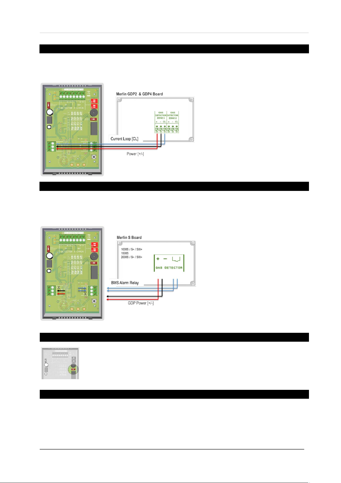
Wiring a Detector (GDP2 or GDP4 Control Panel)
Power is supplied to a detector via the GDP terminal [+ / -] and using the panel [GAS DETECTION ZONE] terminal.
If you are using a GDP panel you will need to use the detector [C/L] terminal as an alarm relay.
BMS terminals can be used in conjunction with
other external relays that affect other devices
and controls such as purge fans or audible
alarms etc.
Wiring your Detector (Merlin ‘S’Control Panels)
Power is supplied to a detector via the GDP terminal [+ / -] and using the ‘S’ panel [GAS DETECTOR] terminal [+ / -].
For a BMS alarm relay use [COM] and [NC] on the detector and the [open/close] switch terminal on the panel.
BMS are volt free connections.
A relay will change state when in alarm or
when gas is detected.
BMS terminals can be used in conjunction with
other external relays that affect other devices
and controls such as purge fans and audible
alarms etc.
Audible Alarm Switch
There is a switch on the detector board identified as [Buzzer On/Off].
The detector can be configured to have an audible alarm or not when gas levels reach the alarm
set points. The alarm will continuously sound –there are no provisions to silence the alarm, gas
levels must drop to a safe value for the alarm to stop.
Factory Set Condition
Buzzer On/Off Switch
ON
Chain Termination Resistor
OFF
Detector ID Switches
ID 1
Detectors are shipped pre-calibrated and configured.

Installation, Operation & Maintenance Manual Merlin Detector-TFT
IOM Iss: 1 05-21 9
Installation Tips
Wiring detector chains
The best way to connect devices in a MODBUS RTU communication is a parallel DAISY CHAIN method.
Cable distance
You may encounter problems when powering detectors beyond 100 yards from one control panel, in this instance,
contact your supplier.
Resistance to interference
Signal communication issues may occur where the bus length is too long, high baud rates are used or signal
reflections are occurring. To avoid this, terminating at each end of a chain may help the quality of the data signal by
turning on the 120ohm terminal resistor switch of the first and last device in the chain.
Earthing/Grounding
If you are encountering noise or irregular or abnormal problems, the problem is likely related to grounding, incorrect
shielding or wiring mains power cables next to data cables. If using a shielded cable –ensure the shielding or
equivalent is wired to the [Shield Wire] terminal on the detectors and connected to a mains powered earth/ground
point on the control panel.
Cable characteristics
For MODBUS communications, a shielded and twisted pair cable is used. The shielding can be of 2 types: braided
[like a mesh of thin conducting wires] or like a foil [consisting of a thin sheet of metal covering the twisted wires].
Detector protection
High concentrations of alcohol found in many products may damage, deteriorate or affect the gas sensing elements of
the detectors –such as; wine; deodorants; stain removers; thinners etc.
Detector identification
Remember to individually ID each connected detector by configuring the ID switches on the circuit board. Make a
plan, map and/or note of the location of all connected detectors for tracing and locality purposes.
Buzzer on alarm
There are no provisions to silence the alarm buzzer when high gas levels are detected. Gas levels must return to safe
level for the buzzer to stop. The audible buzzer is optional via a switch on the circuit board.
Operation
Initial Power-Up (Commissioning)
On connecting power, the detector enters ‘sensor stabilisation’ phase for approximately 60 seconds –during this
period the screen will display an ‘initialisation’ message indicating that the device is not yet ready for gas detection.
After the sensor has stabilised –the screen will display;
a. Target gas.
b. Target gas value.
c. Target gas measurement (parts per million or % LEL).
d. Unique detector serial/batch number.
e. Configured ID number.
We recommend all gas detection systems be commissioned by a competent/trained engineer to ensure
correct installation and operation!
Installation, Operation & Maintenance Manual Merlin Detector-TFT
IOM Iss: 1 05-21 10
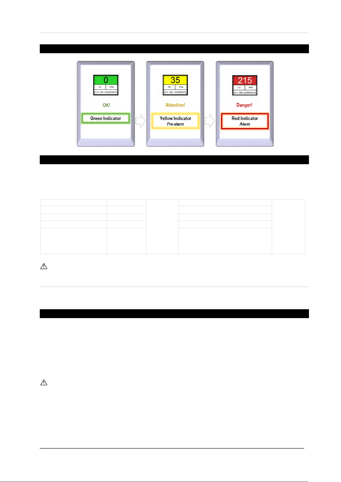
Digital Indication
Alarm Set Points
▲Rising alarm ▼Falling alarm LEL (Lower Explosive Limit) PPM (Parts per Million)
Gas Detector
Pre-Alarm
Buzzer
Alarm State
Buzzer
Methane/Natural Gas (NG)
▲8% LEL
No Sound
▲ 10% LEL
Continuous
sound
Liquid Petroleum Gas (LPG)
▲8% LEL
▲10% LEL
Hydrogen Gas (H)
▲8% LEL
▲10% LEL
Oxygen (O2)
N/A
▼18.5% ▲23%
Carbon Monoxide (CO)
▲ 20 PPM
▲ 20ppm after two (2) hours
▲50ppm after One (1) hour
▲100ppm after Ten (10) minutes
▲ 300ppm after One (1) minute
An audible buzzer will sound if the buzzer switch on the circuit board is on!
General Maintenance
Cleaning
Keep your gas detector in good working order - follow these basic principles;
Remove any dust/debris from the outer enclosure regularly using a slightly damp cloth.
Never use detergents or solvents to clean your device.
Never spray air fresheners, hair spray, paint or other aerosols near the device.
Never paint the device. Paint will seal vents and interfere with the device.
Concentrations of alcohol found in many products may damage, deteriorate or affect the gas sensing elements
such as; wine; deodorants; stain removers and thinners. Other gases and substances to avoid are; corrosives
(i.e. chlorine & hydrogen chloride); alkali metals; basic or acidic compounds; silicones; tetraethyl lead;
halogens and halogenated compounds!

Installation, Operation & Maintenance Manual Merlin Detector-TFT
IOM Iss: 1 05-21 11
Manual Circuit Simulation Test
When the test button on the circuit board is pressed and held the detector will simulate an open
circuit to ensure configured systems, outputs, alarms, indications and other external devices operate
as intended in response to gas. When the test button is released –the test sequence will terminate
and return to normal operation.
Access to the interior of the detector, when carrying out any work, must be conducted by a competent person!
This test does not check the gas sensing element itself!
Bump Test (Gas Response Check)
What is a Bump Test?
Gas response checks are often referred to as a ‘bump test’. Bump tests are important to make sure a device is able to
detect a release of gas as early as possible. The aim of the bump test is to make sure a detector is working at its
optimum by briefly exposing the unit to a known concentration of the target gas that usually exceeds the highest
alarm point. If the detector goes into alarm and all signals/outputs activate, then the system is working safely. If the
system fails to operate as intended in an alarm state, the gas detector must not be used until a full inspection and
service has been conducted.
Why is it important?
A detector may visually appear in good working order, but its sensitivity can be inhibited by external factors. Dust,
humidity, temperature fluctuations, cleaning products, contaminants or sensor drift (ageing) can cause a decline in
sensitivity and eventual failure.
How often?
Regular bump tests are important to make sure the detector is able to detect a release of gas as early as possible and
usually takes seconds (gas type dependant i.e. CO sensors will take over a minute) and is often completed alongside
a scheduled fire alarm test, however the frequency should be determined following an appropriate risk assessment by
the end user. Remember, bump testing does not remove the need to have gas detectors inspected, calibrated and
serviced periodically by a competent person.
What do I need?
Contact your CGS representative for details of suitable bump testing kits and gases. Kits usually consist of a certified
gas cylinder; flow control regulator, tube pipe and applicator cone. We recommend only using CGS calibration gas
kits to ensure correct flow rates meet CGS technical requirements. A bump testing gas is usually a concentration mix
that exceeds the highest alarm set-point.
See below for recommended gas concentrations for bump testing your detector.
Detector Type
Bump Test Gas
Response Time
CO - Carbon Monoxide
400 - 500ppm (balance in air).
<120s
NG - Methane
0.6 - 0.8% BV (balance in air)
<30s
LPG - Liquid Petroleum Gas
0.3 –0.4% BV (balance in air)
<30s
H - Hydrogen
5000 - 6000ppm (balance in air)
<30s
O2- Oxygen
15% (balance in Nitrogen).
<60s
All certified test gases supplied by CGS are classified as non-flammable and non-toxic, however, they do contain gas
under pressure and may explode if heated to extreme temperatures and cause asphyxiation in high concentrations.
Installation, Operation & Maintenance Manual Merlin Detector-TFT
IOM Iss: 1 05-21 12
How to perform a Bump Test?
1. Ensure you have the correct gas for the device type prior to application.
2. Screw and seal the regulator/valve into the gas cylinder outlet.
3. Once sealed, the regulator pressure gauge will indicate cylinder pressure.
4. Offer up the applicator hose/cone to the lower vents.
5. Open the valve/regulator to allow the gas to be delivered at a pre-set flow rate.
7. Wait for the device to enter alarm status and energise configured outputs/relays.
At this point…
9. Remove applicator hose/ cone and turn the gas cylinder regulator/valve off.
10. Wait for the device to return to normal.
11. Reset the system.
Record your test details. There is a provision for this in your control panel manual.
To increase reaction time, cover the escape vents at the top of the device.
Alternatively, enclose the device and apply gas i.e. in an air tight bag or container.
For more help and advice on bump testing –contact us.
Always remove the regulator/valve from cylinder after use!
Always check cylinder pressure upon sealing valve –there may not be a sufficient amount of gas!
All CGS cylinders will re-seal upon removal of the regulator/valve!
Always give at least five (5) minutes between testing the same unit or until gas has fully dispersed!
Always consider safety and use equipment in accordance with Safety Data Sheets!
Service & Field Calibration
Overview
Detectors are pre-calibrated at the time of manufacture, therefore a field calibration is only required periodically
(usually annually) to compensate for its sensitivity and accuracy that can be inhibited by external factors. Dust,
humidity, temperature fluctuations, cleaning products, contaminants or sensor drift (ageing) can cause a decline in
sensitivity, accuracy and eventual failure. Servicing and field calibration is important to prolong the operational life and
ensure the detector is able to detect a concentration of gas as accurately and as early as possible to optimise
protection. Typical accuracy of a detector is ± 10-20% of the standard field gas concentration.
Service and field calibration should coincide with the annual service message prompted on the detection system after
each year of service/operation. The annual timer for service will begin after 5 hours of continuous power irrespective
of whether the system is then used intermittently. Depending on the application and environmental factors, field
calibration can be conducted at a higher frequency determined by the end user following an appropriate risk
assessment but must be executed by a competent person.
Contact your CGS representative for details of suitable field calibration kits and gases to ensure any equipment and
flow rates meet CGS technical requirements.
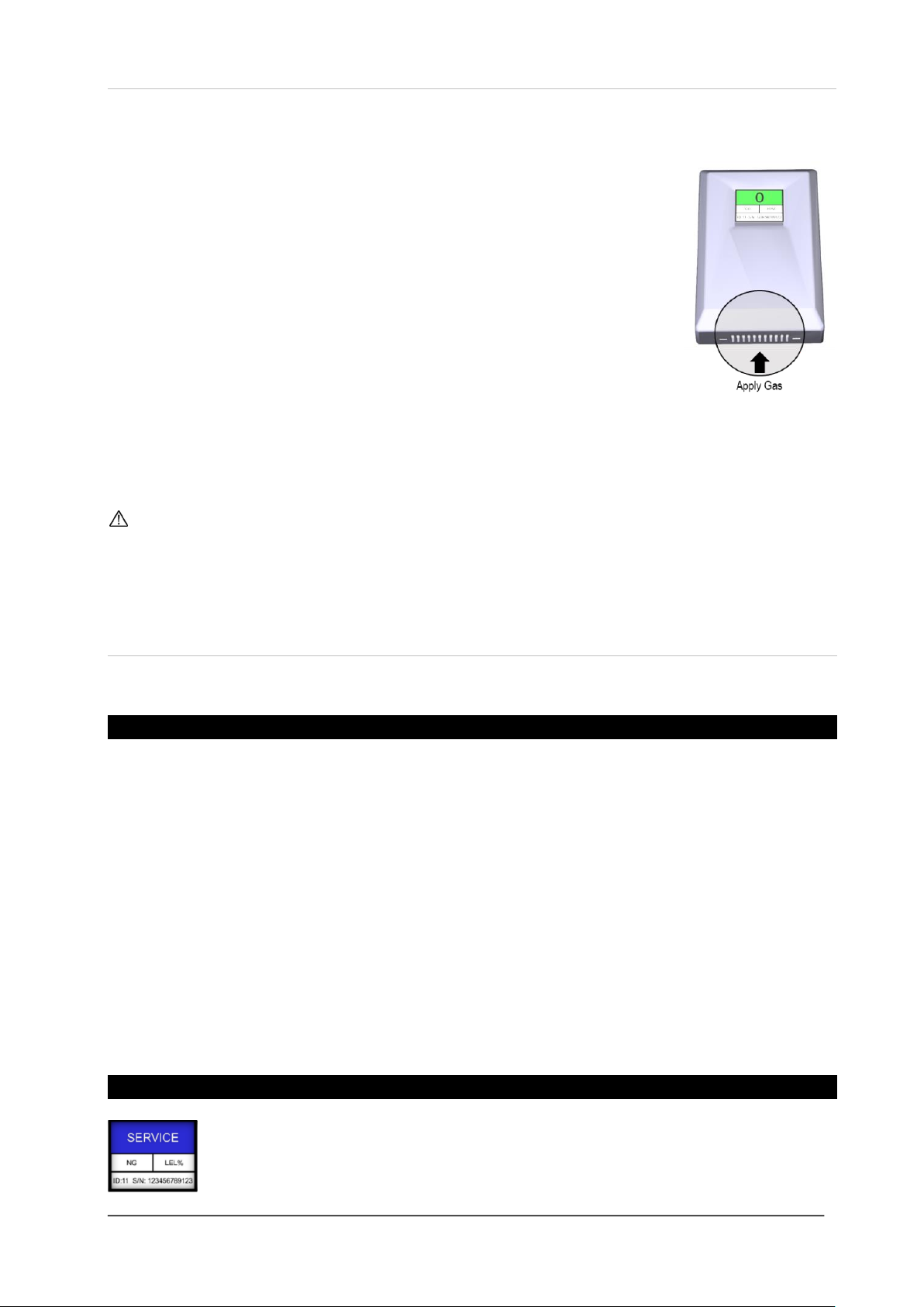
Annual Service Message
A service screen will intermittently flash every 30 seconds after one year of operation. The annual
message reminder will begin after five (5) hours of continuous power irrespective of whether the
system is then used intermittently. The detector will still operate as intended during this time.

Installation, Operation & Maintenance Manual Merlin Detector-TFT
IOM Iss: 1 05-21 13
Service Mode (GDP2X & GDPX+)
Access service mode by pressing the CGS logo on the control panel home screens only. The screen will display a
service prompt. Press Yes. (Note: All alarm signals/outputs will be inhibited for fifteen (15) minutes. Proceed to
service and re-calibrate detectors if required. Upon completion –exit service mode by pressing the ‘Exit’ button on
screen. If you need more time, exit and re-enable service mode. The system returns to a normal state after fifteen (15)
minutes automatically if the ‘exit’ button is not pressed.
When service mode is enabled, the control panel will ignore all alarm signals/outputs and the gas valve will
remain active. The panel will return to a normal operational state after fifteen minutes automatically unless
service mode is disabled manually by pressing the [EXIT] button on screen!
Field Calibration
1. Carefully remove the detector cover to access the circuit board.
2. Ensure that service mode has been enabled on the control panel.
3. Short out the unmarked service headers for ~3s.
4. A calibration prompt will appear for a limited time on the detector screen.
5. Offer up the applicator hose/cone and cover the gas sensor fully.
6. Open the valve/regulator and deliver the gas at a pre-set flow rate.
7. Wait for a ‘successful’ message to appear on the detector screen.
8. Remove applicator hose/cone and turn the gas cylinder regulator/valve off.
9. After ~5s the detector will return to normal operation.
(Note: the annual service reminder is automatically reset)
10. Carefully replace the back cover.
See below for calibrated gas concentrations that must be used to calibrate your detector.
Detector Type
Calibration Gas
CO - Carbon Monoxide
120ppm (balance in air).
NG - Methane
0.5% BV (balance in air)
LPG - Liquid Petroleum Gas
0.2% BV (balance in air)
H - Hydrogen
4000ppm (balance in air)
O2- Oxygen
20.9% (balance in Nitrogen).

Installation, Operation & Maintenance Manual Merlin Detector-TFT
IOM Iss: 1 05-21 14
Gas sensor location, types and response times
The time for sensors to respond to their target gas will vary
on the type of gas sensing element. You should always refer
to the specification for information on sensor type and alarm
levels i.e. electro-mechanical sensors (such as CO and O2)
will react to its target gas slower than semi-conducting
sensor types (such as methane and LPG).
Failed Field Calibration
If field calibration is unsuccessful a screen text ‘Fail’ will appear.
After ~5s the detector will return to a normal state as it was pre-service but the service reminder
message will remain flashing. Check that the correct gas and concentration has been applied and
gas was applied before contacting your supplier.
Access to the interior of the detector, when carrying out any work, must be conducted by a competent person!
Before carrying out any work ensure local regulations and site procedures are followed!
Always give at least five (5) minutes between testing the same unit or when gas has fully dispersed!
Do not conduct calibration of sensors in conditions outside of any recommended ranges!
To recalibrate a detector, the following procedure and gases must be used!
Calibrated gases must be mixed in accordance with recognised standards such as EN 6142.
If a gas sensor is exposed to a concentration significantly above the measuring range, it should be
recalibrated as soon as possible afterwards!
Contact CGS for more information.
End of Operational Life (EOL)
The typical life of a gas detector depends on its application and intended target gas, in addition the operational life
can be prolonged if the system and equipment is installed and maintained in accordance the instructions stated within
this manual.
At the end of its predicted operational life –the detector will display an ‘End of Life’ screen. This
message indicates that the detector has reached its expected operational lifecycle and no gas
levels will be displayed. You must contact your supplier immediately for replacement.
The EOL is approximate from the first five (5) hours of continuous power!
The EOL will depend on the type of gas your detector is targeting and may vary depending on its application
and environmental conditions such as the frequency of exposure to the target gas, poisons or inhibitors!

Installation, Operation & Maintenance Manual Merlin Detector-TFT
IOM Iss: 1 05-21 15
Specification
General
Product:
Gas Detector-TFT
Model(s):
CO (Carbon Monoxide) NG (Methane/Natural Gas) LPG (Liquid Petroleum Gas) H (Hydrogen) O2 (Oxygen)
Use:
Indoor, Safe Areas (not to be used in potentially explosive atmospheres)
Indicators (1.8” TFT Screen)
Green (Safe), Yellow (Special State) & Red (Alarm). Gas Type & Detected Concentration Level. Measured
Value Detector ID No. Serial No. End of Life. Sensor Fault. Service.
Screen Brightness
Non- adjustable
Mounting
Wall Mounting
Electrical
Max. Power Consumption
90mA Max @ 24vdc
Power Voltage Input Range
12-32Vdc (24vdc Nominal)
Communication
RS485, Modbus RTU
BMS Terminal
Volt Free (Normally Closed / Common / Normally Open)
GDP Terminal
24Vdc Power Input (+ - ) & Current Loop (CL)
Relay(s)
1x 30vdc 2A (Non-Latching)
Terminal Wire ratings
Copper 18AWG (0.75mm2) Min. 14 x screw terminals.
Construction
Dimensions (H x W x D)
140 x 95 x 30mm / 5.51 x 3.74 x 1.18”
Unit Weight (Approx.)
0.05kg / 1.77oz
Housing Material
Polylac - PA765
Environmental
Ingress Protection
IP40
Storage Conditions
Dry. Temp: -10 ~ 50°C / 14~ 122°F : 30 ~ 80% rh
Compliance
CE / UKCA
BS EN 50270 / BS EN 61010-1
Sensor Specification
Factory Calibration Conditions
25° ± 5°C - 77° ± 41°F (40-70% RH)
Sensor Operating Temperature
-20C° ~ 50°C (14 ~ 122°F)
Sensor Operating Humidity
Continuous 30-80% rh Non-Condensing
Sensor Operating Pressure
Normal Atmospheric Pressure ± 10%
Gas
Sensor
Indicating
Range
Steps
Calibration
Gas
Response
(t90)
Recovery
(t10)
Alarm: 1
(Pre alarm warning)
Alarm: 2
*EOL
(Years)
Electrochemical Sensors
Carbon
Monoxide
(CO)
0-999ppm
1
120ppm CO
<60s
<60s
▲20ppm
Exposure time.
▲20ppm (after two hours)
▲50ppm (after one hour)
▲100ppm (after ten minutes)
▲300ppm (after one minute)
5
Oxygen
(O2)
0-30% V/V
0.1
Clean Air
(20.9%)
<30s
<60s
N/A
▼18.5% V/V
▲23% V/V
3
Semiconductor Sensors
Methane
(CH4)
0-20% LEL
0.1
0.5% BV
methane
<30s
<30s
▲8% LEL
▲10% LEL
10
Propane
(LPG)
0-20% LEL
0.1
0.2% BV
Propane
<30s
<30s
▲8% LEL
▲10% LEL
10
Hydrogen
(H)
0-20% LEL
0.1
4000ppm
Hydrogen
<30s
<30s
▲8% LEL
▲10% LEL
10
▲ Rising Alarm ▼Falling alarm
*EOL –Expected Operational Life

Installation, Operation & Maintenance Manual Merlin Detector-TFT
IOM Iss: 1 05-21 16
Installation Details
Please pass this manual to the system owner / user.
Date of Installation:
Installation Location:
Organisation:
Stamp/Signature of the installer:
We recommend all Merlin gas detection equipment be commissioned by competent/trained engineers to ensure
correct installation and operation. The Merlin range of gas detectors are calibrated when manufactured, however, we
strongly recommend the detectors response and alarm signals are tested and validated once installed. This will
ensure the equipment performs as intended and is free from any unforeseen damage caused by transit/installation.
Every effort is made to ensure the accuracy of this document; however, CGS can assume no responsibility for any
errors or omissions in this document or their consequences. CGS would greatly appreciate being informed of any
errors or omissions that may be found in the content of this document. For information not covered in this document,
or if there is a requirement to send comments/corrections, please contact CGS using the contact details given below.
Canadian Gas Safety
Telephone: 647-577-1500
Canadian Gas Safety is the owner of this document and reserves all rights of modification without prior notice.
Table of contents
Other CGS Gas Detector manuals


Popular Gas Detector manuals by other brands


Riken Keiki
Riken Keiki GD-84D-EX Series operating manual

Duomo
Duomo BX150 manual

SyxthSense
SyxthSense RGI-CO0-L42 Product sheet

HSS Hire
HSS Hire Safe and Sure 34074 Operating & safety guide

Crowcon
Crowcon Xsafe Bright Installation, operation and maintenance instructions

WatchGas
WatchGas AirWatch Mk 1.0 Quick reference card


