BESCUTTER VERSA Series User manual

USER MANUAL
VERSA Series
MODELS:
VERSA 150 / VERSA CCD / VERSA 260

Models addressed in this manual:
VERSA 150, VERSA 260 and VERSA CCD.
Please keep this user manual within your reach so that you can consult it at any moment. This
manual is considered as a permanent part of the laser system and should be kept with the
machine in case it is resold.
The information and specications included in this manual are valid at the time of its approval for
publication. However, Bescutter Inc., reserves the right to discontinue or change the machine’s
specications and / or design at any time without prior notice and without incurring any legal
obligation. No part of this publication should be reproduced without written permission from
Bescutter Inc.
Last updated July 2020

1. SAFETY ........................................................................................................................ 04
2. UNPACKING AND PRE-ASSEMBLY ................................................................................... 05
3. SYSTEM OVERVIEW ........................................................................................................07
3.1 Mechanical Drive System ............................................................................................. 07
3.2 Optical System ............................................................................................................. 07
3.3 Control System .............................................................................................................08
3.4 Back ............................................................................................................................. 10
3.5 Peripheral Equipment ...................................................................................................10
3.6 Accessories ..................................................................................................................11
4. INSTALLATION ...............................................................................................................12
4.1 Conditioning ................................................................................................................. 12
4.1.1 Work Area Conditioning .......................................................................................... 12
4.1.2 Operator .................................................................................................................. 12
4.1.3 Other adjustments .................................................................................................. 12
4.1.4 Machine leveling. .................................................................................................... 12
4.2 Installation .................................................................................................................. 12
4.2.1 Laser Tube Installation ........................................................................................... 12
4.2.2 Water Chiller Installation ....................................................................................... 14
4.2.3 Fume Extractor Installation .................................................................................... 15
4.2.4 Air Compressor Installation .................................................................................... 15
5. EQUIPMENT INSPECTION AND CALIBRATION .................................................................. 16
5.1 Before turning on the equipment ................................................................................. 16
5.1.1 Start-up process .................................................................................................... 16
5.2 Laser Beam Alignment ................................................................................................. 16
5.2.1 Screw adjustments to guide the path of the laser beam ........................................ 17
5.2.2 Laser test run ......................................................................................................... 17
5.2.3 Laser Beam Alignment: from the tube to the 1st reective mirror .......................... 18
5.2.4 Laser Beam Alignment: between the 1st and 2nd reective mirror .......................... 18
5.2.5 Laser Beam Alignment: between the 2nd and 3rd reective mirror ......................... 20
5.2.6 Vertical alignment: From the 3rd mirror to the laser outlet (nozzle) ....................... 21
6. MAINTENANCE .............................................................................................................. 23
6.1 Water Chiller ................................................................................................................23
6.2 Fume Extractor ........................................................................................................... 23
6.3 Mirrors and Lenses .......................................................................................................23
6.4 Guide Rails ....................................................................................................................23
7. CO2 GLASS LASER TUBE: USE PRECAUTIONS ................................................................. 24
8. TROUBLESHOOTING ....................................................................................................... 25
INDEX

4
• NEVER leave the laser equipment unattended when it is in operation.
• NEVER allow people without proper qualication or training to install, operate or do equipment
maintenance.
• ALWAYS pay attention to the work in progress and be careful to react to any abnormality or possible
threats.
• ALWAYS wear Personal Protective Equipment (P.P.E) such as safety glasses , gloves, footwear,
industrial safety clothing, respiratory and hearing protectors.
• NEVER cut and / or engrave disapproved or dangerous materials such as PVC or other materials that
generate harmful gases.
• NEVER leave the laser tube access door open except when replacing the tube.
• NEVER insert or pass through any object in the path of the laser beam.
• NEVER observe the path of the laser beam directly.
• ALWAYS keep the work table free of combustible, ammable and / or explosive materials.
• ALWAYS keep the work table clean and remove any object other than the material to be cut and / or
engraved.
• NEVER leave the work area cover opened while the laser is operating.
• NEVER cut or engrave metals, mirrors, or highly reective materials to avoid lens or mirror damages.
• ALWAYS conrm that the fume extractor, air compressor and water chiller are working before turning
on the laser.
• ONLY trained personnel are authorized to disassemble or modify the laser machine, since doing so can
result in electrocution due to parts that operate with high voltages.
• ONLY trained personnel are authorized to install, operate, or maintain the laser system.
• ALWAYS wear approved Personal Protective Equipment (P.P.E) to prevent injuries.
• ONLY manufacturer or authorized distributor parts and spare parts are allowed to be used in the laser
system.
• This is a CLASS 4 LASER.
• There can be both visible and non-visible radiation.
• Avoid exposing your skin or eyes to direct or scattered radiation.
• The wave length generated by the laser tube is 10.6um.
• Use approved eye protection for a wavelength of 10.6um when working
with or around the equipment.
• Press the EMERGENCY STOP button located on the LED panel, in case of:
• Fire.
• Abnormal sounds.
• Injuries.
• Any other emergency situation.
1. SAFETY
Laser systems use highly focused and energized light beams to cut, engrave and mark materials. When
used correctly, they are a very powerful manufacturing tool. BE EXTREMELY CAREFUL when working with a
laser system. Read this manual completely before installing, servicing, or operating the equipment. Failure
to follow this manual’s instructions, not using Personal Protective Equipment (P.P.E) or not taking adequate
precautions may result in personal injury or even death.

5
Attention: When placing the machine in its nal location, keep in mind that you must keep
a space wide enough for a correct installation and handling of the laser tube and peripheral
equipment (Chiller, Fume Extractor and, Air Compressor).
Attention: The laser tube is fragile. It
must be handled carefully
1. Use a drill with a 5/16 chuck to remove each
of the screws from the wooden box.
2. Remove all plastic protections and foams that
cover the machine.
3. Open carefully each of the machine’s doors and
remove the boxes and accessories in its interior.
2. UNPACKING AND PRE-ASSEMBLY
The two driving belts may be secured to prevent
rail movement. If so, remove the zip ties and
carefully move the rail back and forth to make
sure it can move freely.
Zip tie to prevent rail movement.

6
4. Remove the steel pallet under the machine, leaving it on its wheels.
In case the oor’s surface is not level, turn the orange Wing Nut to lower or raise the rubber bases of the
leveling caster wheels.

7
3.1 Mechanical Drive System.
3.2 Optical System.
3. SYSTEM OVERVIEW:
Attention:
The front surface of the reection mirror should
be placed facing the laser tube.

8
3.3 Control System
Attention: High voltage power supplies can
generate voltages higher than 10,000V. Strong
static electricity might be generated for a short
period, even when the power supply is off. Do
not directly touch the wires at any time.
Ruida Control System
Ruida Control Panel Ruida Control Board
Attention: When changing the optical lens,
remember that it should be placed with the at
surface facing the work table (down).

9
Control Panel main buttons Power Supply
Electrical Cabinet
10
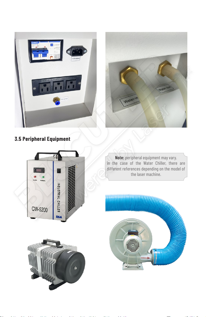
Industrial Water Chiller
Fume extractor:
700 Watts, 3400 r/min, 110V, 60 Hz.
Ducts: Corrugated Rubber Pipe 183cm x 15 cm.
Air Compressor: 110V 60 Hz.
3.4 Back
3.5 Peripheral Equipment
Note: peripheral equipment may vary.
In the case of the Water Chiller, there are
different references depending on the model of
the laser machine.

11
3.6 Accesorios
Toolkit.
Focus measurer to adjust the position of the laser head.
Attention:
There might be certain differences between the accessories
for each model.
12
4.1 Conditioning
4. INSTALLATION
4.1.1 Work Area Conditioning:
Make sure the work area is free of condensed water,
electromagnetism, strong air currents, pollution,
among others. The workplace temperature should
be between 10 ° C and 38 ° C, humidity should
be between 10% and 90%. Make sure of having
access to two 110V/60Hz grounded outlets.
4.1.2 Operator:
The operator must be properly qualied and
trained to install the laser system. Additionally, the
operator must have read this manual and be aware
of the risks involved when working with a category
4 laser or high voltage equipment.
4.1.3 Other adjustments:
Users must prepare the materials and supplies
needed, including: 8 liters of distilled water (you
can use ionized water as a second option) for the
Chiller, two (2) AC110V grounded electrical outlets,
a computer, a proper exhaust system, testing
materials, among others.
4.2 Installation
4.2.1 Laser Tube Installation
Open the rear cabinet door (where the laser tube is placed) and remove the top of the Laser tube mounts.
Attention: do not move or adjust the bottom
parts of the laser tube mounts, because it could
affect the laser path signicantly.
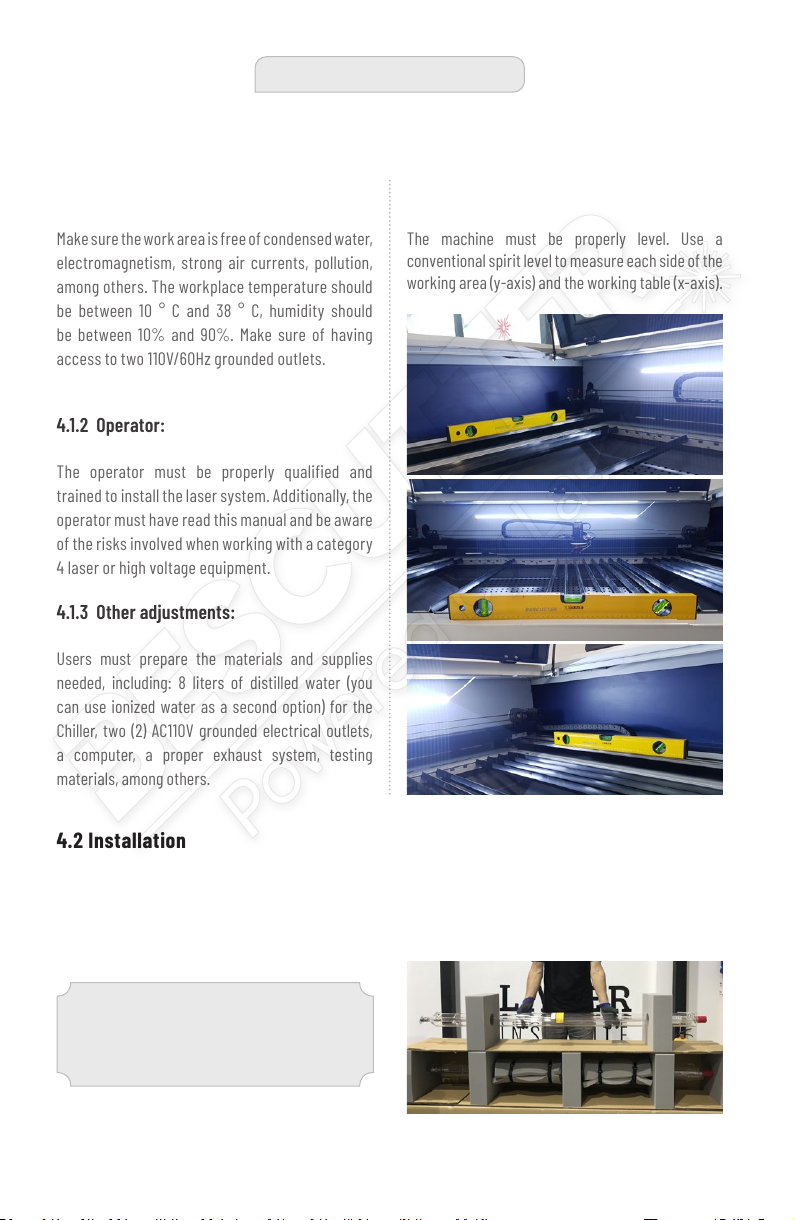
4.1.4 Machine Leveling:
The machine must be properly level. Use a
conventional spirit level to measure each side of the
working area (y-axis) and the working table (x-axis).
13
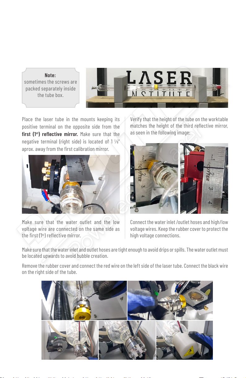
Make sure that the water inlet and outlet hoses are tight enough to avoid drips or spills. The water outlet must
be located upwards to avoid bubble creation.
Remove the rubber cover and connect the red wire on the left side of the laser tube. Connect the black wire
on the right side of the tube.
The laser tube is protected by pads inside its packaging to prevent damage during transport. It takes
two people to carefully remove the laser tube from its packaging. One of the two people should hold
the laser tube rmly by the middle section and the other person should remove the pads that cover it.
It is important that the pads are carefully removed instead of being pulled since both ends of the tube
have connections and water inlets that are fragile.
Place the laser tube in the mounts keeping its
positive terminal on the opposite side from the
rst (1st) reective mirror. Make sure that the
negative terminal (right side) is located of 1 ⅛“
aprox. away from the rst calibration mirror.
Make sure that the water outlet and the low
voltage wire are connected on the same side as
the rst (1st) reective mirror.
Note:
sometimes the screws are
packed separately inside
the tube box.
Verify that the height of the tube on the worktable
matches the height of the third reective mirror,
as seen in the following image:
Connect the water inlet /outlet hoses and high/low
voltage wires. Keep the rubber cover to protect the
high voltage connections.
14
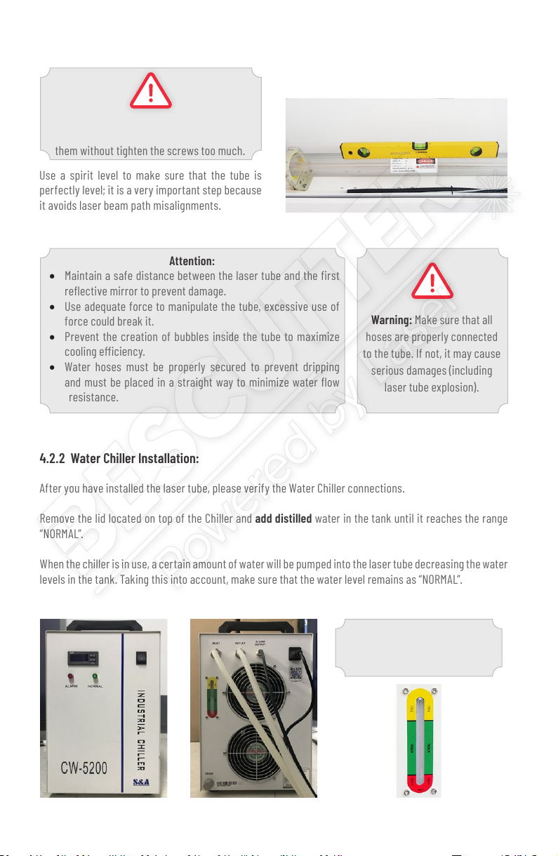
4.2.2 Water Chiller Installation:
Note: the green section
located in the back of the chiller
indicates the “NORMAL” level.
Warning:
Install the upper parts of the mounts and adjust
them without tighten the screws too much.
Warning: Make sure that all
hoses are properly connected
to the tube. If not, it may cause
serious damages (including
laser tube explosion).
Attention:
• Maintain a safe distance between the laser tube and the rst
reective mirror to prevent damage.
• Use adequate force to manipulate the tube, excessive use of
force could break it.
• Prevent the creation of bubbles inside the tube to maximize
cooling eciency.
• Water hoses must be properly secured to prevent dripping
and must be placed in a straight way to minimize water ow
resistance.
After you have installed the laser tube, please verify the Water Chiller connections.
Remove the lid located on top of the Chiller and add distilled water in the tank until it reaches the range
“NORMAL”.
When the chiller is in use, a certain amount of water will be pumped into the laser tube decreasing the water
levels in the tank. Taking this into account, make sure that the water level remains as “NORMAL”.
Use a spirit level to make sure that the tube is
perfectly level; it is a very important step because
it avoids laser beam path misalignments.

15
Then connect the water outlet of the Chiller to the water inlet of the laser machine (WATER-IN) and, the inlet
of the chiller to the outlet of the laser machine (WATER-OUT). Finally connect the signal cable that comes
from the laser machine to the alarm connector (ALARM OUTPUT) of the chiller.
Starting the machine:
After the installation is completed, press the power switch on the Water Chiller. You will hear different
noises (loud beeps). The water should then start to ow into the laser tube. The green light in the front of
the chiller will light when the water ow is correct. If there is any problem an alarm will be generated with
a loud beep and the red light will turn on. If the chiller does not work properly, the laser beam will not be
generated.
Attention:
• Only use distilled water.
• Never turn on the chiller without lling the tank with water.
• The water in the laser tube must ow from the high voltage terminal to the low voltage terminal.
Otherwise, the laser tube could be damaged.
• Change the water every two weeks. In case the room temperature is below the freezing point (32 ° F
or 0 ° C), the water must be drained to prevent water tank damage.
Attention: the air compressor is a very important part of the laser system. Compressed air
passes through the hoses to the laser head removing smoke or any other type of pollutant, regulates
the temperature of the lens and some materials, avoiding the re. The amount of air can be
graduated from the air ow valve. It is important to check the compressor connections and make
sure it is working at all times while the laser is in use.
4.2.3 Fume Extractor Installation:
Connect the corrugated ducts (bellows) from the
machine outlet to the air inlet of the extractor;
adjust it using the metallic clamps. Connect the
fume extractor outlet to an extra exhaust system
for additional air purication.
This ending must be
connectedtothecompressor
outlet, and the other one to
the laser machine air inlet
located in the back (under
the name of ‘Air pump’).
4.2.4 Air Compressor Installation:
To connect the copper adapter to the compressor,
cut 4 cm of one of the silicone hoses of the chiller,
then insert the smaller one and secure the union
using zip ties, as shown in the image:

16
5. EQUIPMENT INSPECTION AND CALIBRATION
5.1 Before turning on the equipment
Before turning on the laser, inspect all connections (electrical, mechanical, peripheral equipment, etc).
In the toolkit you will nd the implements needed
to calibrate the laser system (acrylic, tape, etc).
Next, you will nd an explanation on how to
adjust the mirror screws to perform a successful
calibration of the laser beam.
5.2 Laser Beam Alignment
5.1.1 Start-up process
After turning on the machine and peripheral equipment, make sure that the water from the laser tube ows
in the right direction. Also check that the water inlet/outlet hoses and power cord are connected correctly.
Make sure there there are not air bubbles in the laser tube.
Turning the laser system on:
1. Ensure power supply and make sure that
breaker located in the back of the machine is up.
2. Turn the main power switch to the right.
3. Make sure the emergency switch is not active;
to deactivate it, turn it to the right.
4. Activate the switch (located in the laser unit)
that enables the chiller and the compressor.
5. Turn the chiller on.
6. Turn the fume extractor on.
Turning the laser system off:
1. Turn off the switch that enables the chiller
and the compressor.
2. Turn off the laser unit.
3. Disconnect the fume extractor.
Note: these procedures may vary according
to the laser equipment model.
Warning: The laser head initially moves to the top right corner every time the machine
is turned on, if not, press the “Esc” button to prevent the movement of the laser head.
(Go to section 8 of this manual, for a possible solution).
Warning: The two driving belts may be secured to prevent rail and laser head
movement. If so, remove the zip ties and carefully move the rail back and forth to
make sure it can move freely.

17
The optical system consists of a laser tube, three reective mirrors, an optical lens and, the
laser head. The following diagram corresponds to the path of the laser beam:
CO
Focus
lens
Reflective
Mirror
Reflective
Mirror
Reflective Mirror
Nozzle
Material
Laser
Laser
Laser
Laser
Anode
Cathode
Tube Mount Tube Mount
The laser beam generated by the tube is reected by
three mirrors and is focused through an optical lens
before coming into contact with the material. The
purpose of laser alignment is to ensure that the laser
beam path is correctly centered from the laser tube to
its exit through the laser head nozzle.
5.2.1 Screw adjustments to guide the path of the laser beam
5.2.2 Laser test run
Warning: Be cautious in case you press
the ‘Reset’ button on the control panel because
the laser head will automatically move to the
upper right corner. Make sure that the work
area is free, before operating the machine.
First, press the arrows on the control panel to
make sure the laser head can move freely. If
everything works correctly, continue with the
laser beam calibration.
Note: After turning on the machine, wait for
the control panel to turn on for you to use it.

18
Locate one of the acrylic pieces (provided in the tool
kit), then draw a crosshair or a cross on the acrylic
using a marker. (This is optional).
Cut a piece of double-sided tape and use it to glue
the acrylic to the rst mirror (without dirtying it).
Attention: if after pressing the ‘Pulse’
button, the machine does not generate the
beam, press the red ‘esc’ button twice and
then press ‘Pulse’ again.
Place the acrylic in the mirror making sure that
the cross is located in the center of it. Then
check the maximum power by pressing the
“Max power” button. Congure this parameter
with a value of 30%.
Press the ‘Pulse’ button on the control panel
and verify that the light beam had hit the acrylic
piece (use the same piece to perform the entire
calibration process).
5.2.4 Laser Beam Alignment: between the
rst and second reective mirror.
Step 1: Place the acrylic piece on the second
reective mirror. The second mirror is located on
the left end of the rail.
5.2.3 Laser Beam Alignment: from the tube
to the rst reective mirror
Make sure of keeping a distance of 1 ⅛“
aprox. between the laser tube and the rst
mirror before continuing
(4.2.1 Laser Tube Installation).
Place one of the acrylic pieces on the rst mirror.
Then press the “Pulse” button on the control panel.
Verify that the laser had impacted the center (slightly
tilted to the right) of the rst reective mirror.

19
SCREW
#1
SCREW
#2
SCREW
#3
Step 2: Press the movement buttons on the X-Y axes of the control panel to move the laser head to the top left
end of the work table (the closest position to the rst and second reective mirror). Press the ‘Pulse’ button
and make sure the laser hits within the area corresponding to the second mirror.
Step 3: Press the scroll button on the Y axis to move the rail and laser head to the bottom left end (the
furthest position from the rst reective mirror). Press the ‘Pulse’ button and check if the marks from the
Step 2 and 3 are located one above the other. If not, tighten the screws of the rst reective mirror.
In case the mark from the step 3 is placed:
To the left: loosen the screw #2
Up: loosen the screw #1
Up left diagonally: tight the screw #3
To the right: tight the screw #2
Down: tight the screw #1
Down right diagonally: loosen the screw #3
Make these adjustments until both marks are
located one above the other.

20
5.2.5 Laser Beam Alignment: between the second and third reective mirror:
Step 2: Move the laser head to the furthest
point between the 2nd and 3rd mirror and press
the button ‘Pulse’. Check if the mark matches
the previous one (they overlap each other);
otherwise, tighten the three screws as indicated
in the previous section. (5.2.1 Screw adjustments
to guide the path of the laser beam).
Step 3: After the marks match, move the laser
head from right to left and make new marks by
pressing the button ‘Pulse’ to verify that they
remain one over the other.
Final mark between the 2nd and 3rd mirror:
Respectively, from the second reective mirror
up to the third, the laser should t into the central
part of the mirror. If not, calibrate the laser again
until it hits the center of the third reective mirror.
Note:
the screws on the first mirror already
are calibrated. In this step the screws to
be manipulated are those from the 2nd
REFLECTIVE MIRROR.
Step 1: Place the acrylic piece on the third
reective mirror. The laser head must remain at
the minimum distance between the 2nd and 3rd
reective mirror. Press the ‘Pulse’ button and
check the position of the laser mark.
In case the mark from the step 3 is placed:
To the left: loosen the screw #2
Up: loosen the screw #1
Up left diagonally: tight the screw #3
To the right: tight the screw #2
Down: tight the screw #1
Down right diagonally: loosen the screw #3
Make these adjustments until both marks are
located one above the other.
This manual suits for next models
3
Table of contents
Other BESCUTTER Cutter manuals


