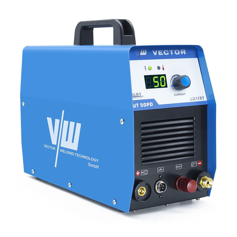
Vector Welding SIWM DIGITAL Paris700 User manual

OPERATING INSTRUCTIONSOPERATING INSTRUCTIONS
Paris700 Cutting Machine
Register now
and benefit!
Jetzt Registrieren
und Profitieren!
www.smart-iwm.com

VECTOR DIGITAL – We optimize the quality and prices
Looking to the future, sustainability, environment friendly and high on the customer-oriented
competence - the key words to which we are responsible.
For this reason, we develop our own powerful brand VECTOR .
In VECTO R weldin g equipm ent c omb ines adv anced i nvert er techn olo gy,th e hig hest
quality standards of a premium brand and low prices to a unique value for money. Inverter
technology is an essential component of process improvement and minimizes energy
consumption. In all our equipment, we therefore trust on the MOSFET technology from
Toshiba and Infineon IGBT technology from SIEMENS. Their innovative solutions are
setting new standards in welding technology.
VECTOR welding equipment can be used on nearly all weld able metals. It is particularly
suitable when quality welds are extremely important. Private gardening - motorcycles,
cars, trucks, classic cars, model making, stair and balcony railings or in the professional
and industrial sectors such as Oil pipeline, chemical, automotive, shipbuilding, boiler,
electric power construction, nuclear power, aerospace, military, industrial installation,
brid g e c o nstr u ction and othe r indu s tries , the high e st q uali t y r e quire m ents a re met
successfully with VECTOR welding equipment.
V E C TOR i s o n e o f t h e l e ading s uppli e r s o f w e l d i ng e q u ipmen t - d i s c o v e r o u r
possibilities - profit from our vision to offer modern, high-performance welding
equipment at unbeatable prices.
On the basis of 4 strategic objectives, our company work day by
day to optimize this vision:
◆Number 1 in Technology
◆Number 1 in the prices
◆Number 1 in Service
◆Number 1 in the environmental compatibility
More than 30,000 enthusiastic customers trust our equipment in the welding and plasma
technology. They confirm the success of these trendsetting strategy. In addition to the
stringent quality test and the test in the production, we subject the equipment a thorough
inspection before delivery. We guarantee delivery of spare parts and repair of all equipment.
The customer is served during and after the warranty period from us. In case of problems,
call us , we are always available. You are also welcome to visit us. Highly qualified employees
are dedicated to carrying out their various tasks with expertise and passion. Our motivated
team will always find a positive solution for you. Everyone is welcome to test our equipment
in detail under the guidance of our experts.
Private gardening, industry or professional, in every area you win if you rely on technology
of welding equipment from VECTOR.
For questions or suggestions, please contact us.www.smart-iwm.com
WARNINGS
Read and understand this entire Manual and your employer’s safety
practices before installing, operating ,or servicing the equipment.
While The operating instructions provide an introduction to the safe
use of the products.
• Read the operating instructions for all system components!
• Observe accident prevention regulations!
• Observe all local regulations!
• Confirm with a signature where appropriate.
Record the following information for Warranty purposes:
Where Purchased:
Purchase Date:
Serial NO.:
Published by:
VECTOR WELDING TECHNOLOGY GMBH
Hansestrasse 101.
51149, Koln, Germany
www.smart-iwm.com

1.1 Arc welding damage--------------------------------------------------------------01-04
1.2 Effects of low frequency electric and magnetic fields----------------------- 04-04
1.3 Symbol chart------------------------------------------------------------------------ 05-05
1. Safety instructions
3.Operation
3.2 Installation Instructions------------------ ------------------------------------------- 11-14
3.1 Layout for the panel----------------------------------------------------------------- 08-11
4.Troubleshooting
4.1 Troubleshooting--------------------------------------------------------------------- 14-16
5.Maintenance
5.1 Maintenance------------------------------------------------------------------------- 17-17
2.Summary
2.2 Specifications------------------------------------------------------------------------ 06-07
2.1 Brief Introduction-------------------------------------------------------------------- 06-06
2.4 Packaged Items---------------------------------------------------------------------- 07-07
2.3 -----------------------------------------------------------------------------07-07Duty cycle
WARNING
PROTECT YOURSELF AND OTHERS FROM POSSIBLE SERIOUS INJURY OR DEATH.
KEEP CHILDREN AWAY. PACEMAKER WEARERS KEEP AWAY UNTIL CONSULTING
YOUR DOCTOR. DO NOT LOSE THESE INSTRUCTIONS. READ OPERATING/INSTRU-
CTION MANUAL BEFORE INSTALLING, OPERATING OR SERVICING THIS EQUIPMENT.
Welding products and welding processes can cause serious injury or death, or damage
to other equipment or property, if the operator does not strictly observe all safety rules
and take precautionary actions.
ELECTRIC SHOCK can kill.
Touching live electrical parts can cause fatal shocks or severe burns. The electrode and
work circuit is electrically live whenever the output is on. The input power circuit and
machine internal circuits are also live when power is on. In semi-automatic or automatic
wire welding, the wire, wire reel, drive roll housing, and all metal parts touching the welding
wire are electrically live. Incorrectly installed or improperly grounded equipment is a hazard.
1. Do not touch live electrical parts.
2. Wear dry, hole-free insulating gloves and body protection.
3. Insulate yourself from work and ground using dry insulating mats or covers.
4. Disconnect input power or stop engine before installing or servicing this equipment.
Lock input power disconnect switch open, or remove line fuses so power cannot be
turned on accidentally.
5. Properly install and ground this equipment according to its Owner’s Manual.
WARNING
1.1 Arc Welding Damage
Safe practices have developed from past experience in the use of welding and cutting.
These practices must be learned through study and training before using this equipment.
Some of these practices apply to equipment connected to power lines; other practices
apply to engine driven equipment. Anyone not having extensive training in welding and
cutting practices should not attempt to weld.
Safe practices are outlined in the European Standard EN60974-1 entitled: Safety in
welding and allied processes Part 2: Electrical HAVE ALL INSTALLATION, OPERATION,
MAINTENANCE, ANDREPAIR WORK PERFORMED ONLY BY QUALIFIED PEOPLE.
Safety instructions
01
CUTTING SERIES EQUIPMENT

WARNING FLYING SPARKS and HOT METAL
can cause injury.
Chipping and grinding cause flying metal. As welds cool, they can throw off slag.
1. Wear approved face shield or safety goggles. Side shields recommended.
2. Wear proper body protection to protect skin.
WARNING ARC RAYS can burn eyes and skin,
NOISE can damage hearing.
Arc rays from the welding process produce intense heat and strong ultraviolet rays that
can burn eyes and skin. Noise from some processes can damage hearing.
1. Wear a welding helmet fitted with a proper shade of filter to protect your face and eyes
when welding or watching;
2. Wear approved safety glasses. Side shields recommended;
3. Use protective screens or barriers to protect others from flash and glare;
warn others not to watch the arc;
4. Wear protective clothing made from durable, flame-resistant material(wool and leather)
and foot protection;
5. Use approved ear plugs or ear muffs if noise level is high;
6. Never wear contact lenses while welding.
WARNING FUMES AND GASES can be hazardous
to your health.
Welding produces fumes and gases. Breathing these fumes and gases can be hazardous
to your health.
1. Keep your head out of the fumes. Do not breathe the fumes.
2. If inside, ventilate the area and/or use exhaust at the arc to remove welding fumes
and gases.
3. If ventilation is poor, use an approved air-supplied respirator.
4. Work in a confined space only if it is well ventilated, or while wearing an air-supplied
respirator. Shielding gases used for welding can displace air causing injury or death.
Be sure the breathing air is safe.
5. Do not weld in locations near degreasing, cleaning, or spraying operations. The heat
and rays of the arc can react with vapours to form highly toxic and irritating gases.
6. Do not weld on coated metals, such as galvanized, lead, or cadmium plated steel, unless
the coating is removed from the weld area, the area is well ventilated, and if necessary,
while wearing an air- supplied respirator. The coatings and any metals containing these
elements can give off toxic fumes if welded.
WARNING WELDING can cause fire or explosion.
Sparks and spatter fly off from the welding arc. The fly sparks and hot metal, weld spatter,
hot workpiece, and hot equipment can cause fires and burns. Accidental contact of
electrode or welding wire to metal objects can cause sparks, overheating, or fire.
1. Protect yourself and others from flying sparks and hot metal.
2. Do not weld where flying sparks can strike flammable material.
3. Remove all flammables far away from the welding arc. If this is not possible, tightly
cover them with approved covers.
4. Be alert that welding sparks and hot materials from welding can easily go through small
cracks and openings to adjacent areas.
5. Watch for fire, and keep a fire extinguisher nearby.
WARNING CYLINDERS can explode if damaged.
Shielding gas cylinders contain gas under high pressure. If damaged, a cylinder can
explode. Since gas cylinders are normally part of the welding process, be sure to treat
them carefully.
1. Protect compressed gas cylinders from excessive heat, mechanical shocks, and arcs.
2. Install and secure cylinders in an upright position by chaining them to a stationary support
or equipment cylinder rack to prevent falling or tipping.
3. Keep cylinders away from any welding or other electrical circuits.
4. Never allow a welding electrode to touch any cylinder.
5. Use only correct shielding gas cylinders, regulators, hoses, and fittings designed for the
specific application; maintain them and associated parts in good condition.
6. Turn face away from valve outlet when opening cylinder valve.
7. Keep protective cap in place over valve except when cylinder is in use or connected
for use.
8. Read and follow instructions on compressed gas cylinders, associated equipment.
WARNING ENGINE FUEL can cause fire or explosion.
Engine fuel is highly flammable.
1. Stop engine before checking or adding fuel.
2. Do not add fuel while smoking or if unit is near any sparks or open flames.
3. Allow engine to cool before fuelling. If possible,check and add fuel to cold engine before
beginning job.
4. Do not overfill tank — allow room for fuel to expand.
5. Do not spill fuel. If fuelling is spilled, clean up before starting engine.
6. Be aware that welding on a ceiling, floor, bulkhead, or partition can cause fire on the
hidden side.
7. Do not weld on closed containers such as tanks or drums.
8. Connect work cable to the work as close to the welding area as practical to prevent
welding current from travelling long, possibly unknown paths and causing electric
shock and fire hazards.
9. Do not use welder to thaw frozen pipes.
10. Remove stick electrode from holder or cut off welding wire at contact tip when not
in use.
0302
Safety instructions Safety instructions CUTTING SERIES EQUIPMENT CUTTING SERIES EQUIPMENT

WARNING
SPARKS can cause battery gases to explode;
BATTERY ACID can burn eyes and skin.
Batteries contain acid and generate explosive gases.
1. Always wear a face shield when working on a battery.
2. Stop engine before disconnecting or connecting battery cables.
3. Do not allow tools to cause sparks when working on a battery.
4. Do not use welder to charge batteries or jump start vehicles.
5. Observe correct polarity (+ and –) on batteries.
WARNING STEAM AND PRESSURIZED HOT COOLANT
can burn face, eyes, and skin.
The coolant in the radiator can be very hot and under pressure.
1. Do not remove radiator cap when engine is hot. Allow engine to cool.
2. Wear gloves and put a rag over cap area when removing cap.
3. Allow pressure to escape before completely removing cap.
NOTE
To reduce magnetic fields in the workplace, use the following procedures.
1. Keep cables close together by twisting or taping them.
2. Arrange cables to one side and away from the operator.
3. Do not coil or drape cable around the body.
4. Keep welding Power Source and cables as far away from body as practical.
5. The people with heart-pacemaker should be away from the welding area.
1.2 Effects Of Low Frequency Electric and Magnetic Fields
1.3 Symbol Chart
Note that only some of these symbols will appear on your model.
Electric current flowing through any conductor causes localized Electric and Magnetic
Fields (EMF). The discuss on the effect of EMF is ongoing all the world. Up to now, no
material evidences show that EMF may have effects on health. However, the research
on damage of EMF is still ongoing. Before any conslusion, we should minimize exposure
to EMF as few as possible.
WARNING MOVING PARTS can cause injury.
Moving parts, such as fans, rotors, and belts can cut fingers and hands and catch loose
clothing.
1. Keep all doors, panels, covers, and guards closed and securely in place.
2. Stop engine before installing or connecting unit.
3. Have only qualified people remove guards or covers for maintenance and troubleshooting
as necessary.
4. To prevent accidental starting during servicing, disconnect negative (-) battery cable
from battery.
5. Keep hands, hair, loose clothing, and tools away from moving parts.
6. Reinstall panels or guards and close doors when servicing is finished and before
starting engine.
0504
Safety instructions Safety instructions CUTTING SERIES EQUIPMENT CUTTING SERIES EQUIPMENT

2.1 Brief Introduction
Paris700 plasma cutting machines adopts the latest pulse width modulation (PWM)
technology and insulated gate bipolar transistor (IGBT) power module, which can change
work frequency to medium frequency so as to replace the traditional hulking work frequency
transformer with the cabinet medium frequency transformer. Thus, its characterized
with portable, small size, light weight, low consumption and etc.
Paris700 plasma cutting machines Characteristics:
◆IGBT technology
◆With EMI filter to minimize the pollution of the electrified net
◆High mains voltage tolerance±15%to maintain stable work.
◆MCU control system, responds immediately to any changes.
◆Excellent cutting capability.
◆Pilot arc controller, can cut grid workpiece.
2.2 Specifications
Description
Weight
Power Source Dimensions
Cooling
Welder Type
European Standards
Number of Phases
Nominal Supply Voltage
Nominal Supply Frequency
Welding Current Range
Single Phase Generator Requirement
Welding Output, 40ºC, 10 min.
Open circuit voltage
Protection Class
Quality Cutting Thickness (500mm/min)
Maximum Cutting Capacity
Maximum Input Current
Effective Input Current
SIWM DIGITAL Paris700
10 kg
Fan Cooled
Inverter Power Source
EN 60974-1 / IEC 60974-1
1
400V +/- 15%
50/60Hz
20 - 70A
13.8A
10A
15kVA
70A @ 60%, 108V / 57A @ 100%, 101.7V
311V DC
IP23
15mm (Steel cutting capability / Thickness to scale.)
20mm (Steel cutting capability / Thickness to scale.)
◆
Intelligent protection: over-current, over-heat, when the mentioned problems occoured, the
alarm lamp on the front panel will be on and the output current will be cut off. It can self-protect
and prolong the using life.
CUTTING SERIES EQUIPMENT
Summary
2.3 Duty Cycle
2.4 Packaged Items
Due to variations that can occur in manufactured products, claimed performance, voltages,
ratings, all capacities, measurements, dimensions and weights quoted are approximate
only. Achievable capacities and ratings in use and operation will depend upon correct
installation, use, applications,maintenance and service
◆Plasma Torch 4m AG60
◆300A earth clamp with 2.5m cable
◆2.5m Power cable
◆2.8m Gas Hose 8x13.5
◆Operating Manual
The rated duty cycle of a Welding Power Source is a statement of the time it may be
operated at its rated welding current output without exceeding the temperature limits of the
insulation of the component parts. To explain the 10 minute duty cycle period the following
example is used. Suppose a Welding Power Source is designed to operate at a 60% duty
cycle, 70 amperes at 108 volts. This means that it has been designed and built to provide
the rated amperage (70A) for 4 minutes, i.e. arc welding time, out of every 10 minute
period (60% of 10 minutes is 4 minutes). During the other 6 minutes of the 10 minute period
the Welding Power Source must idle and be allowed to cool.
Duty Cycle(PERCENTAGE)
Welding Current(AMPS)
25 50 75 100 125 150 175
0
1 0
2 0
3 0
4 0
5 0
6 0
7 0
8 0
9 0
1 0 0
200 2 25 250275 3000
Safe
Operating
Region
NOTE
Summary
CUTTING SERIES EQUIPMENT
H365mmxW/160mmxD380mm
0706

Operation CUTTING SERIES EQUIPMENT
CUTTING SERIES EQUIPMENT
3.1 Layout For The Panel
Operation
Front
Behind
0908
12
6
8
3
4
5
7
9
10

10
Operation CUTTING SERIES EQUIPMENT
11
CUTTING SERIES EQUIPMENT Operation
4. Cutting current adjustment
Clockwise rotate to enlarge the current, and anti-clockwise rotate to reduce the current.
CAUTION
Loose welding terminal connections can cause
overheating and result in the male plug being
fused in the bayonet terminal.
5. Positive Welding Output Terminal
The positive cutting terminal is used to connect the cutting output of the power source
to the appropriate welding accessory such as earth clamp. It is essential, however, that
the male plug is inserted and turned securely to achieve a sound electrical connection.
6. Plasma Torch Connector
Plasma torch insert in to connect with the machine. It’s necessary to be sure that the
plug is correctly and tightly connected to maintain the electricity and gas supply.
DO NOT TOUCH the electrode wire while it is
being fed through the system. The electrode
wire will be at welding voltage potential.
1. Digital Display
The digital meter is used to display the pre-set (preview) amperage for cutting and the
actual cutting current.
2. Power Indicator
The green power indicator will be illuminated when the welder is turned ON and indicates
the presence of power.
WARNING
7. Plasma torch control Switch
Remote control Switch receptacle is used to connect a plasma torch trigger switch:
To make connections, align keyway, insert plug, and rotate threaded collar fully clockwise.
The socket information is included in the event the supplied cable is not suitable and it is
necessary to wire a plug or cable to interface with the receptacle.
3. Thermal Overload Indicator Light
This welding power source is protected by a self resetting thermostat. The indicator will
illuminate if the duty cycle of the power source has been exceeded. Should the thermal
overload indicator illuminate the output of the power source will be disabled. Once the
power source cools down this light will go OFF and the over temperature condition will
automatically reset. Note that the mains power switch should remain in the on position
such that the fan continues to operate thus allowing the unit to cool sufficiently. Do not
switch the unit off should a thermal overload condition be present.
8. Pilot connection
The plasma torch is connected to the pilot port on the machine. Here is theArc generated
by pressing the button on the burner. (contactless ignition).
9. Power switch
Connect 230V power supply before using the machine. Pull the switch to the closure
state of “AN” to operate the machine, and pull the switch to “AUS” after use. Turn off
the power input, and the machine will stop operating.
10. Gas input port
Th e gas port is c onnec ted w ith t he g as v alve output port. After conne cti on, c heck
wh eth er the re is gas leaka ge. (As sho wn in the pictu re of s ectio n 2.5: Gas va lve
as sem bly).
3.2 Installation Instructions
In order for the unit to function correctly, it must be installed properly. Follow the procedure
given below for correct installation:
1. Read the safety rules given in this manual carefully.
2. Check on receiving the unit that there are no defective parts or parts damaged during
transportation.
3. Attach air regulator as show in picture Air Regulator Installation only for Paris700.
4. Set your unit up in an area which is adequately ventilated and make sure that the air
vents are not obstructed.
5. Connect the power supply cable to a socket located as near as possible to the work area,
so that the unit can be switched off quickly in case of emergency.
6. Your machine has a 16 amp plug fitted, before use check that the green/yellow earth is
connected to the earth pin socket of fitted plug.
7. Make sure that the mains supply switch and any fuses have a value which ± 15% the
maximum current absorbed by the unit. All fuses should be the slow-blow type.
8. Any extensions of power supply cable should have the same cross-section as the power
supply cable. The extension leads, however, should only be used when absolutely
necessary. It is important to note that any extension of mains cables or torch cables will
possibly affect the cutting performance of this cutting equipment, due to the fact that the
resistance of the cable will reduce voltage input, which is determined by the length of the
cable. The supplied length of main cables and torch cables is recommended.
9. Fasten the earth clamp to the piece to be cut, If the surface of the piece to be cut is
painted, rusty or covered with insulating material, clean the surface so that
satisfactory contact between the piece and the earth clamp can be obtained.
10. Make sure that the torch has been assembled with the correct components and that the
cutting tip is suitable for the cutting current.
11. Connect air to regulator and adjust regulator to deliver 5-6 bar 90ltr/min.
12. Switch the unit on using the main switch located on the back side.
13. press the cutting torch to achieve a pilot from the copper tip, when this pilot is up to the
work piece , cutting operation begins.

CUTTING SERIES EQUIPMENT
CAUTION
CAUTION
CAUTION
Do not point the torch jet at foreign bodies.
Avoi d u nnec essa ry ligh ting of the p ilot arc t o pre v ent exce ssiv e
con sump tion of the elec trod eand noz z le.
During cutting the speed of the torch movement should be in accordance with the
thickness of the piece to be cut. Excessive speed causes a return of incandescent
towards the torch which shortens the life of the parts of the torch most subject to
wear and tear. The metal fouling on the nozzle should be removed as soon as possible.
power supply
Air compressor
Plasma torch
Earth clamp
Air regulator installation and operation
1. Firmly tight and seal the copper air hole at IN and OUT terminal by high pressure rubber tube .
2.Tight and seal the meter with meter face rubber tube.
3.Fix the connecting shelf with screw as the regulator position.
4.Get down the plastic screw and fix the regulator on the shelf.
Operation Operation
12 13
5.Turn on the air valve, turn up the pressure adjusting knob, turn the pressure volume
(meter inside shows kg), and then put down the knob.(+ means increasing pressure,
- means decreasing pressure.)
6.Scale of the meter is as follow. The volume in the picture is 6 kg.
7. If the water in thegas filtering bottle is too much, please turn on the water valve to let the
water go out.
Connecting shelf
Pressure adjusting knob
Pressure meter
Air filting bottle
Air pipe
Air out
Air in
Drainage interface
4.1 Troubleshooting
◆Before arc welding machines are dispatched from the factory, they have already been
debugged accurately. So forbid anyone who is not authorized by us to do any change to
the equipment!
◆Only professional maintenance personal who is authorized by us could overhaul the machine!
◆Maintenance course must be operated carefully. If any wire becomes flexible or is misplaced,
it maybe potential danger to user!

◆Guarantee to shut off the arc welding machine’s power before turn on the outline of the
equipment!
◆If there is any problem and has no the authorized professional maintenance personal,
please contact local agent or the branch company!
Nr.
1
5
2
3
4
Troubles Solution
Fan is broken and the control board
broken
The input or output of the air flow
around the machine is blocked
Faulty components in the machine Consult the dealer or manufacturer
to repair
Change fan and control board
Fan blocked
Over-heat appear
Correct the condition
Check and correct it
let meachine cool down 5 minutes
and make sure the duty cycle is
not exceeded
Input voltage is not correct Choose the proper voltage
Connect correctly
Change the power light
Change it
Change it
Connect correctly
Repair or change it
Change it
Change it
Install and screw properly
Check and change
Install and screw properly
Adjust the gas pressure to 65psi/
4.5 bar,the barometer indicate up
to 0.4Mpa or 60psi.
Clean it and change the control
board
Change capacitor and control
board
There is something in the fan and
the control board broken
The start capacitor of fan damaged
and the control board broken
The power light damaged or
connection is not good
The tip or electrode is unfitted
installation
The power cable connected not
good
The light of the power indicator is
broken and the problems mentioned
in Nr. 2
Change the light of the power
indicator or refer to the solution
in Nr. 2
The input lines not corretly connected
The power board is broken
The power cable is broken
The power board is broken
The shield cup is unfitted installation
Cutting torch is broken or mistake
Gas pressure too low
Power on switch is damaged
Turn on the
power source,
power indicator
is lit, fan and air
control valve are
not working
The over-heat
alarm is on after
a few minutes
cutting
Turn on the
power source,
fan is working,
power indicator
is not lit
Turn on the
power source,
fan is not working,
power indicator is
not lit
Turn on the power
source, Torch/Gas
indicator is on
Reasons
Display panel is broken
6
Input voltage is not correct
Torch parts broken
Gas pressure too low or too high
Faulty components in the machine
When torch is
pressed the torch
failed to ignite the
arc
Inspect torch parts and replace
if necessary
Adjust it to proper rate
Consult the dealer or manufacturer
to repair
Choose the proper voltage
CUTTING SERIES EQUIPMENT
Troubleshooting Troubleshooting
CUTTING SERIES EQUIPMENT
14 15
If there are some simple troubles of WSME-series welding machine, you can consult the
following overhauling chart:
Nr.
7
8
9
10
11
12
Troubles Solution
Gas pipe not connected or pressure
is too low
Input voltage is not correct
Gas pressure too low or too high
The gas distributor is uninstalled
Torch parts are worn
The cutting torch is broken
Power supply is overheated
Torch consumbles are worn
Air regulator is broken
Incorrect setting of cutting current
Cutting current is too low Increase the cutting current
Reduce cutting speed
The movement of torch is too fast
Faulty components in the machine
Change or repair it
Check and replace
Change it
Consult the dealer or manufacturer
to repair
Check the gas connection, adjust the
proper setting
Consult the dealer or manufacturer
to repair
Check and adjust the cutting current
Consult the dealer or manufacturer
to repair
Excessive oil or moisture in torch
Do not directly start to cut before
cleaning the torch
Check the air pressure and air flow lack of air pressure
Check and adjust the gas setting
at least 65psi/4.5 bar
let meachine cool down 5 minutes
and make sure the duty cycle is
not exceeded
Check and change the torch parts
Consult the dealer or manufacturer
to repair
Install it
Machine is in trouble
The connection between cutting
torch and machine is not correct o
r the connection is poor
Check the torch leads are properly
connect to the machine
Earth clamp not correctly connect to
the work piece
Gas pressure too low , the torch/gas
indicator is on when torch switch is
pressed
Make sure the earth clamp has a
proper connection to a clean and
dry area of the workpiece
Adjust it to proper rate
Choose the proper voltage
Faulty components in the machine
When torch is
pressed the torch
is difficult to ignite
After triggering
the torch ,the pilot
arc cannot change
to the cutting pilot
Arc shuts off during
operation and it will
not restart when
torch is triggered
The power indicator
is on ,fan is working
but no gas flow , gas
indicator is on
low cutting output
Torch can cut but
the quality is poor
Reasons

O bserve tha t whether panel k nob and switch in the fro nt an d at the
back of a rc we ld ing machine are f le xible ane put corre ctly in p lace.If
the knob has not been put correctly in place, please correct, If you can’t
correct or fix the knob, please replace immediately
If the switch is not flexible or it can’t be put correctly in place, please
re place immed iately; P lease get i n touch wit h maintenan ce servi ce
department if there are no accessories
Af ter tur n-on pow er, w atch /lis ten t o t hat whe ther the arc w e ldi ng
machine has shaking, whistle calling or peculiar smell. If there is one
of the a bove p roble m s, f i nd o ut t he r e ason t o g e t r i d of, if y ou c an’t
find out the reason, Please contact local this area agent or the branch
company
Observe that whether the display value of LED is intact. If the
display number is not intact, please replace the damaged LED. If it still
doesn’t work, please maintain or replace the display PCB
Observe that whether the min/max value on LED accords with the set
value.If there is any difference and it has affected the normal welding
craft, please adjust it
Check up that Whether fan is damaged and is normal to rotate or control
. If the fan is damaged,please change immediately.If the fan does not
rotate after the arc welding machine is overheated, observe that whether
there is something blocked in the blade,if it is blocked,please get rid of;
If the fan does not rotate after getting rid of the above problems, you can
poke the blade by the rotation direction of fan.If the fan rotates normally,
the start capacity should be replaced; If not, change the fan
Observe that whether the fast connector is loose or overheated. If
the arc welding machine has the above problems,it should be fastened
or changed
Observe that Whether the current output cable is damaged. If it is
damaged, it should be wrapped up, insulated or changed
Using the dry compressed air to clear the inside of arc welding machine.
Especially forclearing up the dusts on radiator, main voltage transformer,
inductance, IGBT module, the fast recover diode and PCB, etc
Check up the bolt in arc welding machine,if it is loose,please screw
down it.If it is skid, please replace.If it is rusty,please erase rust on bolt
to ensure it works well
Whether the actual current accords with the displaying value.If they
does not accord, they should be regulated.The actual current value can
be measured by the adjusted plier-type ampere meter
Measure the insulating impedance among the main circuit,PCB and
case, if it below 1MΩ,insulation is thought to be damaged and need to
change, and need to change or strengthen insulation
Date
Daily
examination
Monthly
examination
Quarter-
yearly
examination
Yearly
examination
Maintenance item
◆Warning:For safety while maintaining the machine,please shut off the
supply power and wait for 5minutes,until capacity voltage already drop
to safe voltage 36V!
5.1 Maintenance
In order to guarantee that arc welding machine works high-efficiently and in safety,it must
be maintained regularly.Let customers understand the maintenance methods and means
of arc w elding machine more, ena bl e customers to carry on si mp le examin at io n and
safeguarding by oneself,try one’s best to reduce the fault rate and repair times of arc
welding machine, so as to lengthen service life of arc welding machine.Maintenance
items in detail are in the following table.
Troubleshooting CUTTING SERIES EQUIPMENT
16
Table of contents
Other Vector Welding Cutter manuals
Popular Cutter manuals by other brands

Dexter Laundry
Dexter Laundry GL-DP1236A instruction manual

Makita
Makita SC103D instruction manual

Powermatic
Powermatic SLR12-700 instruction sheet

Huskie Tools
Huskie Tools REC-434YC Operating instructions manual

Worx
Worx WX801L manual

Quality Commercial Macines
Quality Commercial Macines QCM-8200M user manual

Secabo
Secabo T60 II operating instructions

Altuna
Altuna ERREBI DELTA ADVANCE instruction manual

Piranha
Piranha B Series Safety, operation and maintenance manual

Greenlee
Greenlee EBS12ML Service manual

Rothenberger
Rothenberger ROCUT XL 225 Instructions for use

Lissmac
Lissmac COMPACTCUT 800 operating manual