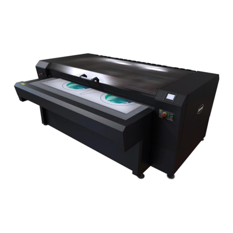
SILLA S26 Guide

CESOIA MOD. –S26 –S32 –S36 –S40 –S45 –S50 –S55
Operating, maintenance, spare parts manual Rel. 3 dated 02/07/2019 Pagina 19 di 54
Manuale di uso, manutenzione e ricambi
Operating, maintenance, spare parts manual
CUTTING MACHINE
mod. - S26 - S32 - S36 -
S40 - S45 - S50 –S55
REL. 3 Date 02/07/2019

CUTTING MACHINE MOD. –S26 –S32 –S36 –S40 –S45 –S50 –S55
Operating, maintenance, spare parts manual Rel. 3 dated 02/07/2019 Pagina 20 di 54
TABLE OF CONTENTS
Page
6.1
Adjusting the machine
28
7
OPERATION
28
7.1
Control instruments
28
7.2
Machine operation and controls
28
7.2.1
Start push button
28
7.2.2
Emergency stop push button
28
7.2.3
Lever control
28
7.2.4
Knob control
28
7.3
Operation of the machine
29
7.3.1
Starting the machine
29
7.3.2
Stopping the machine
29
7.3.3
During operation
29
7.3.4
Warning signs
29
8
MAINTENANCE
30
8.1
Recommended lubricants
30
8.2
Ordinary maintenance
30
8.3
Extraordinary maintenance
30
8.4
Bolt torque
31
8.5
Troubleshooting
31
8.6
Maintenance of hydraulic unit
31
8.7
Ordering spare parts
31
9
DISMANTLING
32
9.1
Disassembling and dismantling
32
9.2
Demolition
32
10
DECLARATION OF
CONFORMITY
33
11
WARRANTY REGISTRATION
FORM
35
12
SPARE PARTS MANUAL
From
37
1.INTRODUCTION AND GENERAL PROVISIONS
This manual is directed at the user and operator who will be responsible for the safe, efficient and trouble free operation of the
machine. Read and understand this manual and always follow the safety precautions outlined in the Instruction and Safety
Manual. Keep this manual handy for frequent reference and to pass on to new operators or owners.
The machine is equipped with tested special safety devices and safety systems. SILLA cannot be held responsible for
unauthorized modifications or procedures, replacements and/or all other modifications changing the use the machine has been
designed and manufactured for.
Warranty:
The mechanical and electrical products of the machine, which are not normal service items, have a one-year warranty starting
from the date of the sale. The warranty does not cover the normal service items like tools, driving belts, liquids and oils.
The defective or not properly working products will be replaced by the Technical Personnel of the Manufacturer of the machine,
after the defective product has been proven to be defective. The warranty does not cover the products in case of modification,
abuse, misuse, improper use, negligence or improper maintenance (routine and extraordinary maintenance) as shown by this
I.M. This warranty is valid in the territory of the European Community. The consumer is the right holder according to the
applicable national laws governing the sale of consumables and this warranty makes those rights unprejudiced.
2.MARKING
A label with the following machine identification data is located on the machine:
EC marking according to EC directive 2006/42, Enclosure III;
Name and address of the manufacturer and/or legal representative in Europe;
Machine designation;
Machine type;
Serial or part number;
Year of construction.
TABLE OF CONTENTS
Page
1
INTRODUCTION
20
2
MARKING
20
2
ABBREVIATION LIST
20
3
GENERAL PRECAUTIONS
21
4
CHARACTERISTICS
22
4.1
Description of the machine
22
4.1.1
Machine body
22
4.1.2
Cutting unit
22
4.1.3
Control unit
22
4.2
Technical characteristics and
dimensions
23
4.3
Safety prescriptions
23
4.4
Noise
24
4.5
Conformity with safety
regulations
26
5
INSTALLATION/NEW BUILDING
YARD
24
5.1
Transport
24
5.2
Placing and earthing
25
5.3
Areas of respect and dimensions
25
5.4
Pre-operation checklist
26
5.5
Safety first
26
5.6
Putting into operation
26
5.7
Electric installation
26
5.8
Diagrams
26
5.8.1
Three-phase wiring diagram
27
5.8.2
Single-phase wiring diagram
27
5.8.3
Oil-pressure diagram
27
5.9
Training
28
6
ADJUSTMENTS
28

CUTTING MACHINE MOD. –S26 –S32 –S36 –S40 –S45 –S50 –S55
Operating, maintenance, spare parts manual Rel. 3 dated 02/07/2019 Pagina 21 di 54
For assistance and information or spare parts, refer to:
SILLA Macchine Edili e Stradali Srl
Via S.Gimignano , 96
53036 –POGGIBONSI (SI) - ITALIA
Tel. ++39-0577 - 938051 Fax. ++39-0577 –981609
This INSTRUCTION MANUAL and all the enclosed documents are freehold property
of the Company SILLA.
Reproduction (in any form or way inclusive recording and photocopy) in whole and/or part is forbidden without the
written authorisation of the Company SILLA.
In case this Instruction Manual should get lost or destroyed ask the Company SILLA for a complete copy.
LIST OF ABBREVIATIONS AND DEFINITIONS USED IN THIS MANUAL
Danger
Source of probable injuries to the health
Dangerous area
Any area inside and/or next to a machine where the presence of a person is a risk for the safety and the
health of said person.
Exposed person
Any person, in whole or in part, inside a dangerous area.
Operator
Person or persons having the task of install, making it work, regulating it, carrying out maintenance
procedures, cleaning, repairing and transporting a machine.
Hazard
Combination of probabilities and seriousness of probable injuries to the health in a dangerous situation.
Guard
Machine element specifically used for granting protection by means of a material barrier.
Protection device
Device (other than a guard) reducing the hazard, alone or together with a guard.
Authorized use
The use of the machine according to the information given by the instructions for use.
Not authorized but
reasonably predictable
use
The use of the machine different from that shown in the instructions for use, but which can derivate from
easily predictable human behaviour.
Caution: precautions and instructions to be strictly followed.
3. GENERAL PRECAUTIONS
The operating safety of the machine is only granted for the functions listed in this instruction manual. SILLA
cannot accept any responsibility, if the machine should be used for different uses than those listed in this
manual or uses, which do not comply with the operating instructions.
SILLA cannot accept any responsibility for safety, liability and performances of the machine, if the precautions and the
instructions of this instruction manual, especially referred to use on building yards, maintenance and dismantling are
disregarded.
The correct use of this cutting machine implies good knowledge of these instructions for use and the hazards connected
with its possible incorrect use.
Consequently, the cutting machine shall only be used by skilled and authorised personnel. The operator using the cutting
machine shall be trained on its correct use, the relevant protection devices and the accessory tools.
The operating safety of the cutting machine is only guaranteed for the functions and the materials listed in this instruction
manual.
SILLA cannot accept any responsibility, if the cutting machine is used for other purposes than those outlined in this manual
and which do not comply with the operating instructions.
The cutting machine shall not be used in places with the presence of gas, inflammable liquids or other inflammable
materials. The machine shall not be installed in environments with risk of explosion
SILLA cannot accept any responsibility for safety, liability and performances of the machine, if the precautions and the
instructions of this instruction manual, especially referred to: use, ordinary and extraordinary maintenance and repair are
disregarded.
The electric installation of the user shall comply with the CEI 64.8 standards ( CENELEC HD 384).
The Manufacturer cannot accept any responsibility, if the cutting machine is not properly connected to the unipotential
earthing system and if there are no protection devices installed upstream, which are coordinated to ensure automatic cut-
off, according to the standards mentioned before.
For maintenance works needing some components to be replaced, only use original spare parts or spares authorized by
the Technical Dept. of Silla.
In particular, ensure the maintenance of the electric installation is carried out by specialised and authorised personnel and
by using original components.
However, for service or repair works always refer to the After-Sales Service recommended by the supplier of the cutting
machine.

CUTTING MACHINE MOD. –S26 –S32 –S36 –S40 –S45 –S50 –S55
Operating, maintenance, spare parts manual Rel. 3 dated 02/07/2019 Pagina 22 di 54
The user of the cutting machine takes full responsibility for its good and safe operation, if the machine was not repaired or
maintained by the specialized or authorised personnel.
The cutting machine is delivered with the protection devices already installed and fixed. Check and maintain these
protection devices and the whole cutting machine per the schedule recommendations.
Do not wear any jewellery or clothing that can get caught or distract from the operation of the machine.
Ensure good lighting (natural or artificial) of the cutting machine and the control panel to avoid shady areas, dangerous
dazzling and stroboscopic effects.
For extraordinary maintenance and repair use only original spare parts. For all repairs, please refer to the After-Sales
Service authorised by the supplier of the machine.
All the above-mentioned operations shall be carried out in an appropriate place with the machine switched off and the
electric supply cable disconnected, in order to prevent other persons from starting the machine.
All the operators using the machine shall be trained on its correct use, the safety devices, the behaviour and actions to
perform for a correct use of the machine and operators’ safety.
During the use on the construction site, the machine shall be protected against falling objects by means of a solid plank
covering (see also art. 114 DLgs 81/08)
The machine is delivered with the protection devices already installed; however, the operator shall check their good working
before starting to use the machine. Check and maintain these protection devices and the complete machine according to
the maintenance schedule. The operator shall reflect upon the possible consequences before approaching with his hands,
in particular:
- NEVER SWITCH ON THE MACHINE WITHOUT THE PROTECTION SHIELDS;
- NEVER REMOVE AND NEVER OPEN THE PROTECTION SHIELDS WHEN THE MACHINE IS RUNNING.
- NEVER SWITCH ON AND NEVER START WORKING WITH THE MACHINE IF THERE ARE BYSTANDERS.
The machine has a considerable mass; therefore do not use it in case of storms. Electrocution hazard!
Clear the area of unauthorized personnel or obstacles, before starting work.
The operator shall wear appropriate clothing: work gloves, safety shoes, etc. Do not wear any jewellery or clothing that can
get caught on the machine.
Follow the safety precautions, in particular:
Switch off the machine before opening or cleaning it; ensure no one can turn it on by accident;
Use the protective equipment (work gloves, safety shoes, etc.) during use, assembly and maintenance of the machine;
Be cautious in approaching all the moving parts.
Follow the safety instructions shown in chapter SAFETY PRECAUTIONS.
4. CHARACTERISTICS
4.1 Description of the machine
The cutting machine has a metal structural work structure. The following are the machine units:
4.1.1 Machine body.
The machine body has a welded metal structural work base, a screwed casing manufactured from sheet, a case protecting the
cutting area (see section 5.4) and wheels.
4.1.2 Cutting unit.
The cutting unit has a single-acting oil-pressure cylinder, which is connected to the arm of the cutting machine and controls the
operation of the cutting blade. Cylinder reversal is done by means of two pull springs anchored to the machine body. A pump
driven by an electric motor, which is connected to a flow distributor, feeds the cylinder with oil. Under the base there is tank for
the oil.
4.1.3 Control unit.
This unit has a control lever (4.1.3.1), a start button (4.1.3.2), a stop button (4.1.3.3), a safety switch in the cutting area (4.1.3.4)
and a box with outlet 4.1.3.5.

CUTTING MACHINE MOD. –S26 –S32 –S36 –S40 –S45 –S50 –S55
Operating, maintenance, spare parts manual Rel. 3 dated 02/07/2019 Pagina 23 di 54
4.2 Technical characteristics and dimensions
Technical data of Cutting Machines:
TECHNICAL DATA
S 26
S 32
S 36
S 40
S 45
S 50
S 55
LENGTH (mm)
890
1050
1150
1330
1330
1330
1330
WIDTH (mm)
510
530
600
680
680
680
680
HEIGHT (mm)
850
910
730
870
870
870
870
WEIGHT (Kg)
150
215
250
370
380
420
550
Electric motor
3
3
3
4
4
5,5
7,5
4.3 SAFETY PRESCRIPTIONS Limits for use, space, endurance
The cutting machine has been designed for continuous working 8 hours/day; it can also be used for 16 or 24
hours/day by suffering a proportional loss of endurance. Electric energy shall be used according to the parameters
shown in section 5.7.
The electrical connection shall be carried out according to the parameters shown in the “wiring diagram”of page 9.
The cutting machine shall be installed in a covere place with ambient temperature between +5° C and + 40° C and
humidity up to 90 % at 20° C.
Lack of appropriate maintenance, as recommended in section 8, will reduce both endurance and reliability of the
cutting machine.
The machine shall not be used in places at risk for explosions or fires (gas/powders) (no Ex protection). The machine
has been designed and built just for cutting structural steel in different configurations (rod iron, square and flat drawn
iron) on building yards.
Metal drawn products, made from low-carbon steel with dimensions deducible from the following schedule:
The cutting machine performances may be different according to various external factors and to the type of product
being processed.
In view of its specificness it is not possible to use the cutting machine for purposes other than those outlined in this
instruction manual. Furthermore, the manufacturer cannot foresee other ways of using the machine, according to
point 1.1.2 letter C of EEC directive 2006/42.
Ensure the areas of respect of the machine, according to its range of action and the relevant work area, also in view of
the dimensions of the materials to be cut.
Do not exceed machine limits. Do not modify the machine to improve its performances.
Leaving the machine unattended in public places is dangerous. Therefore, provide appropriate barriers around the
work area to prevent unauthorized persons from approaching it.
Do not make attempts to repair the machine, always call authorized repair shops.
Serious infection or toxic reaction can develop from hydraulic fluid piercing the skin surface. Wear proper hand and
eye protection when searching for a high-pressure hydraulic leak. Use a piece of wood or cardboard as a backstop
instead of hands to isolate and identify a leak. Should the oil pierce the skin surface, seek medical attention
immediately.
Before connecting or disconnecting any electric component, you must know very well the electric system. A wrong
connection may cause injuries and damages.
Oil is a special waste and must be disposed of according to the laws in force.
The electric installation of the user shall comply with CEI 64/8 standards and Law 46/90; it shall be equipped with
automatic protection devices, which are coordinated with the earthing system. Ensure good lighting in the work area
and around the machine, in order to avoid shady areas, dangerous dazzling and stroboscopic effects. The
Manufacturer cannot accept any responsibility, if the cutting machine is not properly connected to the unipotential
earthing system and if there are no protection devices installed upstream, which are coordinated to ensure automatic
cut-off, according to the standards mentioned before.
The scrap materials, which are produced during the machining, must be collected and sent to specialized companies
for disposal, according to the laws in force, in order to protect the environment.

CUTTING MACHINE MOD. –S26 –S32 –S36 –S40 –S45 –S50 –S55
Operating, maintenance, spare parts manual Rel. 3 dated 02/07/2019 Pagina 24 di 54
The materials to be processed with their minimum/maximum dimensions are those stated in table 4.3 .
Although the user strictly follows the instructions for use, there still might be some residual hazards during the use of
the machine.
The machine shall be used by qualified and healthy adults only.
CAUTION !!!!!!
EVERY USE OF THE MACHINE DIFFERENT THAN THOSE OUTLINED BY THE MANUFACTURER IN THIS
INSTRUCTION MANUAL IS AN IMPROPER USE. THEREFORE, THE COMPANY SILLA CANNOT ACCEPT ANY
RESPONSIBILITY, IF THE MACHINE SHOULD BE USED BY THE OPERATOR FOR DIFFERENT USES THAN
THOSE LISTED IN THIS INSTRUCTION MANUAL OR THOSE NOT COMPLYING WITH THE OPERATING INSTRUCTIONS.
4.4 Noise
the noise emission level of the Cutting Machine measured at the operator’s ear does not exceed the
maximum value of 63 Pa, according to UNI 11200 standard
In order to not increase the noise level strictly follow these rules:
Clean and grease the machine elements per the schedule recommendations;
Ensure the machine parts are not obstructed or damaged.
With this noise emission level the use of protective equipment like earmuffs, earplugs, etc. is not mandatory but
recommended.
These noise values are emission levels and are not necessarily safe work levels. While there is a correlation between the
emission levels and the exposition levels, it cannot be used in a reliable way to evaluate whether there is or nor the need for
additional precautions. The factors affecting the worker’s real exposition level include the duration of the exposition, the
environmental characteristics, other emission sources like for example the number of adjacent machines and types of
machining. The single exposition levels may also differ from country to country. However, thanks to this information the user of
the machine can better evaluate the dangers and risks.
4.5 Conformity with safety regulations
The Cutting Machine has been designed and built in accordance with the following standards:
“Machinery Safety Directive” EC 2006/42 published in the Official Gazette of European Union on
June 9, 2006.
" Electromagnetic Compatibility Directive " EC 2004/108 , published in the Official Gazette of European Union
on December 31, 2004.
-EN ISO 12100-1 (2003) Safety of machinery - basic concepts, general principles of design –Part 1: basic terminology,
methodology.
-EN ISO 12100-2 (2003) Safety of machinery - basic concepts, general principles of design –Part 2: technical principles.
-EN ISO 14121-1 (2007) Safety of machinery –risk evaluation -Part 1: principles
-EN ISO 13850 (2008) Safety of machinery –emergency stop –principles of design.
5. INSTALLATION / NEW BUILDING YARD
5.1 Transport
The cutting machine is delivered to the Customer fully assembled and tested.
The packed machine, protected with proper material, is assembled on the pallet and fixed to it by means of two tie rods. Fix
the package to the platform of the means of transport by means of proper retention instruments, such as: special belts, ropes,
etc.
Unload the machine by means of suitable means, such as fork lifts, by inserting the forks in the special openings of the pallet.
Then place the machine onto its wheels on a level soil capable of supporting its weight. Before transporting the machine to
another building yard, pack and protect the machine with proper material, assemble and fix it on/to the pallet by means of two
tie rods. Fix the packing to the platform of the means of transport by means of proper retention instruments, such as: special
belts, ropes, etc.
The weight of the machines is outlined on the EC plate and in section 4.2 of this manual; due to their considerable weight you
must provide accurate loading/unloading means.
Ensure your hoisting equipment has adequate dimensions and capacity.
Be careful during hoisting and handling the machine to prevent injury to persons and damage to the machine.
The hoisting equipment shall be dimensioned according to the weight to be hoisted.
The machine is delivered together with the following accessories:
- 1 Instruction Manual for use, maintenance and spare pieces with EC statement of conformance;
- 4 Allen wrenches size 4-5-6-10 for mod. S26 and size 4-5-6-14 for the other models;
- 1 flat setscrew wrench size 13-17 for mod. S26 and size 17-22 for the other models;
- 1 Grease pump (only for mod. S36-40-45-50);
Never hoist the machine by hand, even if you are more than one person: it is too dangerous.
Follow the safety instructions shown in chapter SAFETY PRECAUTIONS

CUTTING MACHINE MOD. –S26 –S32 –S36 –S40 –S45 –S50 –S55
Operating, maintenance, spare parts manual Rel. 3 dated 02/07/2019 Pagina 25 di 54
5.2 Placing and earthing
Place the machine on a steady and level soil. Check the flatness of the soil before installation by means of a
water level (longitudinally and crosswise).
The installation place shall be protected against atmospheric agents. During the use on the construction site,
the machine shall be protected against falling objects by means of a solid plank covering (see also art. 114
DLgs 81/08).
Make sure the soil is correctly dimensioned to support the weight of the machine. It must be self-extinguishing and not
combustible.
Next to the machine there must be a 3 P+T 16A plug for the connection with the electric installation. Connect the machine to
the general ground system of the building yard by means of the power cable. Its resistance shall not exceed 883 Ohm,
otherwise the cutting machine shall be connected to a supplementary ground rod by connecting it to the special ground screw
(earth rod see fig. 2).
In case the machine shall be connected to a generating set, by means of electrical separation (NOT grounded generating set),
the following conditions shall be respected, according to the CEI 64-8 standard:
- the machine shall not be connected to a ground system;
- extension of the circuit below 250 metres;
- realisation of equipotential bonding between machine mass and other equipment mass powered by the same generating
set;
- the power cables shall be properly isolated and it shall be possible to inspect their whole length.
However, follow provisions for electrical separations mentioned in the CEI 64-8 standard.
Make sure there is an area of respect of at least 2000 mm around the machine. During machining the machine produces scrap
and dust, which must be disposed of by specialized companies.
Next to the machine there must be:
Connection to the electric supply mains;
areas for the hoisting and handling of work products;
areas for the collection and discharge of residual products;
Never use the machine near inflammable or explosive materials and/or in places with the presence of gas.
Follow the safety instructions shown in chapter SAFETY PRECAUTIONS.
Unauthorised persons shall never use the machine.
5.3 Areas of respect and dimensions
The area of respect around the machine shall be at least 2 meters to ensure good working and correct
maintenance of the machine. The personnel shall move within this area with the utmost care.
Inside the area of respect the operators shall move with the utmost care and eliminate all kinds of
obstacles hindering the passage. The driving seat may become slippery because of work residuals. Use the
personal protective equipment (safety shoes) and frequently clean the floor.
Caution! The use of additives or special products for cleaning the machine may injury the health of the
person. Carefully read the prescriptions of the relevant products. These products may also modify the quality of the
paint of the Cutting Machine and damage its hydraulic parts.

CUTTING MACHINE MOD. –S26 –S32 –S36 –S40 –S45 –S50 –S55
Operating, maintenance, spare parts manual Rel. 3 dated 02/07/2019 Pagina 26 di 54
5.4 Pre- operation checklist Use work gloves during set-up and setting at work of the machine.
Before the setting at work of the cutting machine, especially at first starting or when it is installed on a new work site, the
following technical advices and suggestions concerning the various types of connections shall be respected.
5.5 La Safety first
All the machines can be dangerous. When the Cutting Machine is correctly used and properly maintained, it is a very
safe machine. On the contrary, if it is badly used, it may become dangerous. Both in this manual and on the machine there are
warning signs showing the possible hazards and how to avoid them. Do not operate the machine, until you are not able to
control it. Do not start any work until you are not sure about your and other people’s safety. You can cause serious damage, if
you try to carry out some non-familiar operations, without prior testing on free areas, far from people and on level ground.
Follow the safety instructions shown in chapter 4.3 SAFETY PRECAUTIONS
5.6 Putting into operation
On delivery the machine is connected to 380 V. Before starting the machine, ensure the following:
- The motor voltage must correspond to the voltage of the external line.
- Grounding according to I.S.P.E.L.S standards is mandatory.
- The feeding cable shall not be below 4x1,5 mm.
-Change-over to 220 V voltage has to be carried out as follows:
a) Change the terminal board from “star” to “delta”
b) Displace the electric connection of the transformer at input from 380 V to 220 V.
Check the area of respect and the work areas;
Check the protections for good fixing;
Check the caution/danger signs on the machine for good visibility.
Test all the mechanical and electric machine controls, loadless, to check correctness, efficiency and working;
Check the oil level inside the tank through the level pilot lamp placed on the rear side of the machine.
5.7 Electric installation
The electric installation of the user must be in compliance with CEI 64.8 standards (Italian law n. 46/90).
The machine is fitted with an electric plug.
The plug must be connected to the installation of the user according to the maximum electrical input.
Provide the following: - Unipotential grounding system,
-The sum of the discharger resistances and the mass of the protection wires shall be below 883 Ohm.
The connector shall be of type 3P +T complying with the CEI 23-12 standard . The supply cable shall be of type
H07RN-F or expressly indicated by the manufacturer for laying outside in wet environments with a section suitable to
the current to be conducted. The cable shall be protected by strong raceways against the passage of means and/or
people.
Voltage drop shall be verified according to the following formula:
=voltage coefficient L= length I = Intensity in ampere line current
K= coefficient (1,73 for three-phase lines) (2 for single-phase lines)
The grounding connection shall be done by means of a self-extinguishing
yellow-green cable, its minimum section shall not be below the one of the supply cable. Ensure grounding of all the
metallic parts of the machine. Ensure the protection against lightning and/or electric discharges.
For installations on building yards, connect to the grounding system of the building yard also the additional external
earthing plug, placed on one machine structure: use a copper cable with a section of 35 square millimetres provided
with cable terminal and fix the cable terminal to the clamp with a screw nut (Fig. 2).
Ensure good lighting and visibility of the machine installation place, according to the work area, and avoid shady
areas, dangerous dazzling and stroboscopic effects. The Company cannot accept any responsibility in case of wrong
connection of the electric system or bad grounding.
The motors on the machine are protected by means of a magneto-thermal device. The motors are provided with special
devices to avoid accidental machine starts after electric cutoff. In the case of intervention of the thermal protections, open by
means of the special screwdriver the electric panel and reset the thermal switch by pressing the green push-button. All the
electric elements and apparatus are protected according to the place of use, they have a protection grade of minimum IP 54
(protection from dust and liquids).
The control panel is placed so that is it visible by the operator, it also houses the supply plug. The machine is provided with a
START/STOP push-button, which is placed on the machine case, on the side with the control level for fast machine
starting/stopping.
Follow the safety instructions shown in chapter SAFETY PRECAUTIONS
5.8 Diagrams
GENERAL FEATURES OF CUTTING M/C
RATED POWER KW 2,2 -3 -4-5,5
RATED CURRENT A 4,4-6- 8-11
RATED VOLTAGE V 400
AUXILIARY VOLTAGE V 24
VALUE OF SHORT-CIRCUIT CURRENT
MAX. = 30 KA
DEGREE OF PROTECTION IP 54

CUTTING MACHINE MOD. –S26 –S32 –S36 –S40 –S45 –S50 –S55
Operating, maintenance, spare parts manual Rel. 3 dated 02/07/2019 Pagina 27 di 54
5.8.1 Three-phase wiring diagram
5.8.2 Single-phase wiring diagram
5.8.3 Hydraulic diagram
Maximum pressure valve
S 26
Single-ph.
S 26
Three-ph.
S 32
Single-ph.
S 32
Three-ph.
S 36
Three-ph.
S 40
Three-ph.
S 45
Three-ph.
S 50
Three-ph.
S 55
Three-ph.
A (l/1')
3.8
6.3
9
11
11
11
11
11
11
B (kW)
2.2
2.2
2.2
2.2
2.2
3
4
5,5
5,5
C (mm)
1/2"
1/2"
3/4"
3/4"
3/4"
3/4"
3/4"
3/4"
3/4"
D (mm)
3/8"
3/8"
½"+1/4"
1/2"+1/4"
1/4"+1/2"
1/4"+1/2"
1/4"+1/2"
1/4"+1/2"
1/4"+1/2"
E (l)
6.5
6.5
9
9
9
9
12
12
12

CUTTING MACHINE MOD. –S26 –S32 –S36 –S40 –S45 –S50 –S55
Operating, maintenance, spare parts manual Rel. 3 dated 02/07/2019 Pagina 28 di 54
5.9 Training
Before starting to use the machine, read this instruction manual and understand how to use
the machine in a safe way.
6 ADJUSTMENTS
6.1 Adjusting the machine
At first operation on the building yard, the machine does not need any adjustments. However, we suggest to read the
following paragraph:
5.4 Pre-operation checklist.
Never carry out adjustments while the machine is running/working.
Do not alter or bypass any active safety devices installed on the cutting machine.
Follow the safety instructions shown in chapter SAFETY PRECAUTIONS.
Every single adjustment and/or modification of the safety/work parameters set on the machine, which has not been
authorised by the technical personnel of the company Silla or which is not outlined in this instruction manual, may
influence the quality of the product and injure the operator’s health. The company Silla decline any responsibility for
liability, performances and safety of the machine in case of modification/alteration of the machine and of the relevant
operation/safety parameters.
7. OPERATION
7.1 Control instruments
The START and STOP push-buttons are placed on the main casing of the Cutting Machine.
The STOP and the Emergency STOP push-button is installed next to the START push-button in a clearly visible way, in
order to stop the machine at any time. To disengage it, turn it clockwise.
The lever control placed on the upper side of the machine, allows the operator to carry out cutting operation by simply
pulling the lever towards him. The control lever activates the cut because the oil enters the hydraulic cylinder.
The control lever automatically returns into home position. The return of the cylinder is possible, even if the blade did not
finish its stroke; you simply need to turn the lever into home position and the circuit reopens, thus allowing the return of the
cutting unit.
During operation, follow the safety instructions shown in chapter SAFETY PRECAUTIONS.
7.2 Machine operation and controls
7.2.1 "START" push-button.
It is used to start the oil-pressure pump or to reinitialise it after the emergency stop push button has been
pressed and after power cutoffs. The oil-pressure pump does not automatically start after a power cutoff; it is
the operator who must decide to start it again.
7.2.2 Emergency stop push-button
It cuts the power supply to the electric motor, which starts the oil-pressure pump in case of need. The push-button is of type
“mechanical interlock with rotary disengagement”; to disengage the push-button it must be turned cw.
Another emergency stop push-button is placed on the machine opposite side in order to stop it at any time.
Do not “play” with the emergency stop push-button. Use these buttons only for the use they have been
designed for.
7.2.3 Lever control
The lever control placed on the upper side of the machine, allows the operator to carry out cutting operation by simply pulling
the lever towards him. The control lever activates the cut because the oil enters the hydraulic cylinder.
The control lever automatically returns into home position.
The return of the cylinder is possible, even if the blade did not finish its stroke; you simply need to turn the lever into home
position and the circuit reopens, thus allowing the return of the cutting unit.
7.2.4 Knob control
The models S 36 - S40 - S45 -S50 –S55 also have a knob, placed on a machine side, for manual or automatic mode selection.
By lowering this knob, before pulling the lever, you can set continuous cutting cycle. Consequently, after pulling the lever once,
you can carry out cuts without the need to pull the lever again. All this is possible thanks to a mechanism that closes the o il
circuit inside the cylinder, after the return of the arm of the cutting machine, thus starting a new cutting cycle.

CUTTING MACHINE MOD. –S26 –S32 –S36 –S40 –S45 –S50 –S55
Operating, maintenance, spare parts manual Rel. 3 dated 02/07/2019 Pagina 29 di 54
7.3 Operation of the machine
7.3.1 Starting the machine
1 –Connect the plug to the socket on the electric board; ensure the supply voltage is equal to the machine voltage.
2 –Lower the protection case of the cutting area.
3 –ONLY FOR MOD. S36 –S40 –S45 –S50: place the aforesaid knob in upper position (manual mode) or in lower position
(automatic mode). 4 –Position the workpiece (or the workpieces) to be cut (see table at section 4.3). 5 –Press the
“START” push-button to start the machine.
Caution! If the protection case of the cutting unit is not closed, the machine will not work.
Do not alter or bypass any active safety devices installed on the cutting machine.
6 –Pull the lever to cut.
7.3.2 Stopping the machine
To switch off/stop the cutting machine, press the emergency stop push-button and cut the electric power supply or unplug.
Keep the cutting machine always switched off when you do not use it.
The operator shall always be careful and concentrate on what he is going to do and on the possible consequences.
7.3.3 During operation
Use the prescribed personal protective equipment.
Never approach the moving and operating elements with your hands, arms or other parts of your body. Remove rubble with
an appropriate device and always when the machine is stopped: never use your hands! In case of accident, press the
STOP push-button and lift the lever in to home position, the oil will automatically come out from the cylinder and
the cutting unit will automatically return into its home position. The same operation shall be repeated if one ore
several bars should jam inside the bar cutting unit.
In case of machine trouble, or something to check, stop the machine and immediately disconnect it from the electric
installation.
During the operation of the machine, of its elements or of its accessories, it is strictly forbidden to remove any protection,
safety switches, carters, barriers or other protection and safety elements. Never modify switches or other safety and/or
operating cycle control devices, because such an intervention could seriously damage the mechanical elements of the
machine and injure the health of the operator.
Pay attention to the operating and the moving parts.
Do not climb or position yourself on or inside the machine, even if it is switched off.
In case of machine trouble, stop the machine with the emergency stop push-button and cut off the electric energy supply
until the trouble has been eliminated.
The operator is the person entitled to operate with the machine and consequently he is the only responsible for it.
7.3.4 Warning signs

CUTTING MACHINE MOD. –S26 –S32 –S36 –S40 –S45 –S50 –S55
Operating, maintenance, spare parts manual Rel. 3 dated 02/07/2019 Pagina 30 di 54
8. MAINTENANCE
The machine does not require any particular maintenance work. The technical solutions and the components
installed on the machine reduce maintenance at the minimum. However, we recommend to carry out a series of
operations, which aim at ensuring safety, liability, efficiency and long life of the machine.
Duing maintenance
Before performing any maintenance work on the machine, disconnect the power cable from
the machine. In case of mechanical or electric trouble, call the authorized personnel. If the machine
is out of service because of trouble, maintenance or repair, place a special sign highlighting this status so as to avoid
accidental starting.
Always use the personal protective equipment (leather gloves of approved type, safety shoes, safety mask and safety
goggles) during repair and replacement of the machine elements.
Repairs of the electric installation shall be done by authorized and specialized personnel only.
Do not approach hands, arms or other parts of your body to the movement and transmission area. Use appropriate means
(brush, wooden piece, etc.) to remove possible rubble: never use your hands!
To ensure long life, prevent damage and ensure the full functioning of the mechanical and electric machine elements the
maintenance must be performed regularly. Periodically check the earthing system, according to the laws in force.
Before starting the machine, ensure there are no tools or foreign matters left inside or on the machine.
8.1 Recommended lubricants
MINERAL OIL
23°E at 50°C –320cSt at 40°C
32°E at 50°C –450cSt at 50°C
AGIP
HYDRAULIC SYSTEM
OSO 68
/
ISO –VG 68/460 TYPE
GREASE
LUBRIC. AND
VARIOUS GEARS
MAKE
TYPE
PENETR.
DRIP
1st LUBRIC.
FOLL.LUBR.
ESSO
BEACON EP 2
265/295
8.2 Ordinary Maintenance - To be carried out every day at the end of the work.
- To be carried out every weeK at the end of the work.
A) DAILY CLEANING AND MAINTENANCE
Stop the cutting machine and cut off the electric energy supply, then remove material residuals and deposits from: the cuttin g
area Caution!! Do not wash with high-pressure water jets.
B) WEEKLY CLEANING AND MAINTENANCE
At the end of the week, after the cleaning of the cutting machine as explained above, provide for:
Check tightening of clamping screws of main moving parts.
Lubricate all the parts, which are not protected by means of painting.
Check the oil level inside the tank through the pilot lamp placed on the rear side of the machine.
Check the safety of the electric system: cable isolation, differential protection device, earthing conductor continuity,
operation of safety switch of cutting area protection.
Check the interlocks of the different mechanical components.
Respect the lubricant replacement frequency (at least every two years), as stated in the lubrication table.
Oil is a special waste and must be disposed of according to the laws in force. IMPORTANT :
Los controles diarios y semanales son muy importantes también a nivel de prevención de las averías.
Daily and weekly checks are very important to prevent machine troubles. In fact, whenever during these checks
you will find some worn or damaged components, immediately order the relevant spare parts to be kept on stock,
before the component has definitively broken with consequent production stop.
8.3 Extraordinary maintenance - Check the safety of the electric system: isolation of cables, working of differential
protection device, continuity of protection wire, working of safety limit switch on guards. - Check interlocks of mechanical
components - Change the lubricants according to the lubrication schedule.
Note**The bushing, the electric motors and all other consumables must be immediately replaced whenever a running defect
occurs.

CUTTING MACHINE MOD. –S26 –S32 –S36 –S40 –S45 –S50 –S55
Operating, maintenance, spare parts manual Rel. 3 dated 02/07/2019 Pagina 31 di 54
8.4 Bolt torque. Tightening is executed by means of dynamometric wrenches, according to the toques shown in the
following pages and in the tables shown below:
LARGE PITCH
SMALL PITCH
Diameter
screw x pitch
Nut torque
Kgm
Screw torque
Kgm
Diameter
screw x pitch
Nut torque
Kgm
Screw torque
Kgm
6 x 1
1,1
1,2
8 x 1
2,7
1,2
8 x 1,25
2,6
2,8
10 x 1,25
5,5
2,8
10 x 1,5
5,1
5,6
12 x 1,25
9,7
5,6
12 x 1,75
8,9
9,7
14 x 1,50
15,3
9,7
14 x 2
14,1
15,5
16 x 1,50
23
15,5
16 x 2
21,5
23,6
18 x 1,50
33
23,6
18 x 2,5
29,5
32
20 x 1,50
46
32
20 x 2,5
42
46
22 x 1,50
62
46
22 x 2,5
57
62,5
24 x 2
79
62,5
24 x 3
72,5
79,5
27 x 2
115
79,5
27 x 3
107
117
30 x 2
160
117
30 x 3,5
145
159
8.5 Troubleshooting
PROBLEM
CAUSE
SOLUTION
The machine does not run
No or low power in the supply line.
The electric plug and socket are not properly
connected.
The cable form the plug to the electric panel is
broken.
A wire has become disconnected inside the panel.
A wire has become disconnected on the terminal
board.
The switch is faulty.
Intervention of a thermal protection.
Tripped fuse.
Check supply line and voltage.
Make a proper connection.
Replace the cable.
Remake the connection.
Remake the connection.
Replace the switch.
Wait some minutes and try again.
Change fuse.
For all other kinds of troubles, please refer to the After-Sales Dept. of the Company SILLA.
CAUTION!!!!! SILLA DECLINES ANY RESPONSIBILITY IN CASE THE MACHINE DOES NOT UNDERGO
MAINTENANCE AS PRESCRIBED IN THIS INSTRUCTION MANUAL AND IN CASE OF USE OF SPARE PARTS
AND ACCESSORIES OTHER THAN ORIGINAL AND NOT APPROPRIATE.
8.6 Maintenance of hydraulic unit
This unit is airtight and waterproof and does not need special maintenance. Periodically carry out level checks and ensure the
oil is always clean. To change the filter cartridge inside the tank, drain the oil (from the plug placed under the tank) and remove
the cover of the cutting machine.
Use only clean containers and fill in the oil through a funnel with filter. Every other
operation on this unit shall be carried out by specialized personnel equipped with
appropriate.
8.7 Ordering spare parts
When ordering spare parts, order the component from the supplier and/or manufacturer of the machine. Always mention the
machine model, part number, type of machine, description of the desired component, quantity and the main features.

CUTTING MACHINE MOD. –S26 –S32 –S36 –S40 –S45 –S50 –S55
Operating, maintenance, spare parts manual Rel. 3 dated 02/07/2019 Pagina 32 di 54
9 DISMANTLING
Before long-term storage (e.g. holidays), follow the instructions below:
1. Carefully clean the whole machine, remove dust, deposits and dirt.
2. Oil all the moving parts exposed to seizure and the mechanical components exposed to oxidation.
3. Store the machine in a dry and ventilated place.
4. Remove the patch cords and whatsoever to prevent unauthorized persons from using the machine.
9.1 Disassembling / dismantling
Before carrying out any dismantling or disassembling operation, disconnect the battery.
- Disconnect all the electric and mechanical components; - Disassemble the driving parts, bridges, motor and brakes. -
Disassemble the oil-hydraulic parts of the distributor, pipes, cylinder, pump and hydrodrive.
- Disconnect and disassemble all the other mechanical components and the wheels.
9.2 Disposal
The following are the materials the machine is made of:
- Painted steel, aluminium and other metallic components. - Plastic materials. - Oil-hydraulic materials
- Electric cables, electric components, electric motor. - Oil
These materials must be disposed of through specialised companies in accordance with current laws in the
country of use.

CUTTING MACHINE MOD. –S26 –S32 –S36 –S40 –S45 –S50 –S55
Operating, maintenance, spare parts manual Rel. 3 dated 02/07/2019 Pagina 33 di 54
DECLARATION OF CONFORMITY
SILLA Macchine Edili e Stradali Srl
Via S.Gimignano , 96 - 53036 –POGGIBONSI (SI) –ITALY
In the person of Mr Neri Angiolo as Legal Representative
declare
under their sole responsibility that the machine:
GENERIC NAME
CUTTING MACHINE
FUNCTION
CUTTING OF REINFORCED CONCRETE RODS
MODEL
S
TYPE
SERIAL NUMBER
TRADE NAME
…
complies with the essential requirements of the directives of the European Parliament and of the
Council:
“Machines 2006/42/CE published in O.G.E.U. on June 9, 2006.
“Electromagnetic compatibility” 2004/108/CE published in O.G.E.U. on
December
31, 2004
Furthermore it is declared that the machine has been designed and built according to the
following harmonised standards:
EN ISO 12100-1 (2003) Safety of machinery -basic concepts, general principles of design - Part 1: basic
terminology, methodology,
EN ISO 12100-2 (2003) Safety of machinery -basic concepts, general principles of design - Part 2:
specifications and technical principles
EN ISO 14121-1 (2007) Safety of machinery –risk evaluation -Part 1: principles
EN 60204-1 (2006) Safety of machinery - electric system of the machine –Part 1: general rules
EN ISO 13857 (2008) Safety of machinery - safety distances to prevent the upper and lower limbs from
attaining dangerous areas
EN ISO 13850 (2008) Safety of machinery –emergency stop –principles of design.
EN ISO 13849-1 (2008) Safety of machinery - parts of the control systems concerning safety -Part 1: general
principles of design one
EN ISO 13849-2 (2008) Safety of machinery - parts of the control systems concerning safety -Part 2:
validation
The legal person entitled to form the technical dossier and that has custody of the
technical documents is
SILLA Macchine Edili e Stradali Srl
Via S.Gimignano , 96 - 53036 –POGGIBONSI (SI) –ITALY
Poggibonsi, date .................. Signature

CUTTING MACHINE MOD. –S26 –S32 –S36 –S40 –S45 –S50 –S55
Operating, maintenance, spare parts manual Rel. 3 dated 02/07/2019 Pagina 34 di 54

CUTTING MACHINE MOD. –S26 –S32 –S36 –S40 –S45 –S50 –S55
Operating, maintenance, spare parts manual Rel. 3 dated 02/07/2019 Pagina 35 di 54
11. WARRANTY REGISTRATION FORM
Machine type
Part number
IMPORTANT
This form must be filled out and stamped by the Dealer at the time of purchase of the machine.
The Dealer or the buyer must send this form by registered mail to the After-Sales Dept. of the
Company SILLA within 3 days from the purchase, together with a copy of the delivery note or of
the invoice.
The mailing of this form, together with a copy of the transport document or a copy of the
invoice, is an essential requirement to start warranty period.
The warranty is void if not registered.
Date . . . . . . . . . . . . . . . . .
Stamp and Signature of the Dealer
Messrs.
SILLA Macchine Edili e Stradali Srl
Via S.Gimignano , 96 - 53036 –POGGIBONSI (SI) –ITALIA
11.1 WARRANTY CONDITIONS
Warranty means the repair and/or the replacement of those parts, which are proven to be defective in
manufacture. The replacement of the whole machine is excluded.
The warranty is for the period of 1 year from the date of delivery to the user, that is to say the date written in
the Warranty Registration Form.
The defective materials must be sent, free delivered, to our factory. After technical approval the material will
be replaced and sent carriage forward.
The warranty expires in case of:
modifications, repairs, alterations of the machine carried out by the buyer and not expressly authorised by
SILLA.
improper assembling or failure to use the machine according to the instructions of the instruction manual.
The electric components are not covered by this warranty, because a wrong connection done by the user
and/or line problems may cause damage to these components.
Any repair under warranty will not interrupt the warranty period.
We recommend to the dealers to write the part number of the Cutting Machine
both on the delivery note and on the invoice.

CUTTING MACHINE MOD. –S26 –S32 –S36 –S40 –S45 –S50 –S55
Operating, maintenance, spare parts manual Rel. 3 dated 02/07/2019 Pagina 36 di 54

CESOIA MOD. –S26 –S32 –S36 –S40 –S45 –S50 –S55
CUTTING MACHINE MOD. –S26 –S32 –S36 –S40 –S45 –S50 –S55
Manuale Ricambi Rev. 3 del 02/07/2019Pagina 37 di 54
Parts Manual Rel. 3 of 02/07/2019
“I ”-RICAMBI -
“GB” - PARTS MANUAL -

CESOIA MOD. –S26 –S32 –S36 –S40 –S45 –S50 –S55
CUTTING MACHINE MOD. –S26 –S32 –S36 –S40 –S45 –S50 –S55
Manuale Ricambi Rev. 3 del 02/07/2019Pagina 38 di 54
Parts Manual Rel. 3 of 02/07/2019
Tav. 01
Complessivo Telaio
Frame group
Cesoia S26 –
Cutting machine S26
I
GB
Rif
Codice
1
S.26.01.001
Perno
Pin
2
S.26.01.002
Oliatore
Lubricator
3 S.26.01.003 Anello Seeger Seeger
4
S.26.01.004
Vite
Screw
5
S.26.01.005
Rondella
Washer
6
S.26.01.006
Contatto elettrico
Electric contact
7
S.26.01.007
Maniglia
Handle
8
S.26.01.008
Protezione coltelli
Blades protection
9
S.26.01.009
Spess. avvicinam. coltello fisso
Parcking for blades fixed
10
S.26.01.010
Rullo scorrimento ferro
Roller coil sliding
11
S.26.01.011
Coltello
Blade
12
S.26.01.012
Rondella
Washer
13
S.26.01.013
Vite
Screw
14
S.26.01.014
Dado
Nut
15
S.26.01.015
Vite
Screw
16
S.26.01.016
Distanziale
Spacer
17
S.26.01.017
Vite
Screw
18
S.26.01.018
Bronzina
Bushing
19
S.26.01.019
Braccio
Cutting lever
20
S.26.01.020
Oliatore
Lubricator
21
S.26.01.021
Vite
Screw
22
S.26.01.022
Carter
Casing
23 S.26.01.023 Supporto soffietto Hood support
24
S.26.01.024
Soffietto
Cover
25
S.26.01.025
Pomello
Pommel
26
S.26.01.026
Leva
Lever
27
S.26.01.027
Vite
Screw
28
S.26.01.028
Dado
Nut
29
S.26.01.029
Grano
Screw
30
S.26.01.030
Bilanciere
Rocker
31
S.26.01.031
Perno
Pin
32
S.26.01.032
Anello Seeger
Seeger
33
S.26.01.033
Molla
Spring
34
S.26.01.034
Boccola
Bushing
35
S.26.01.035
Vite
Screw
36
S.26.01.036
Dado
Nut
37
S.26.01.037
Cerniera
Fixed hinge
38
S.26.01.038
Biella
Rod
39
S.26.01.039
Dado
Nut
40
S.26.01.040
Vite
Screw
41
S.26.01.041
Vite
Screw
42
S.26.01.042
Supporto
Rocker holder
43
S.26.01.043
Molla braccio
Arm spring
44
S.26.01.044
Dado
Nut
45
S.26.01.045
Tubo di drenaggio
Hose
46
S.26.01.046
Rondella
Washer
47
S.26.01.047
Perno
Pin
48
S.26.01.048
Copiglia
Split pin
50
S.26.01.050
Telaio
Frame
51
S.26.01.051
Tappo olio
Oil cap
52 S.26.01.052 Motore Electric motor
53
S.26.01.053
Metà giunto lato motore
Joint motor side
54
S.26.01.054
Gomma per giunto
Rubber joint
55
S.26.01.055
Metà giunto lato pompa
Semi-joint pump side
This manual suits for next models
7
Table of contents

