BETOPPER Moving Laser User manual
Model: LS3000RGB
Please read the manual carefully before using
Moving Laser
User Manual
201830478508.1

Product warranty card
Please fill in the following content properly future maintenance.
Accordingly, for your each purchase of our systems wehave archive
Serial number and parameters for future reference.
Attention
1. Do not look directly at the bulb while the light is on.
Page 1
2.Follow the instructions. Do not disassemble the unit by yourself. Please
contact the skilled peoplein the event of aoperating problem.
3.The unit shallbeinstalled by professionals.
4.Place the unit away from the strobe light.
5.Keep the unit dry. Do not expose the unit to rain, moisture or dust.
Waterproof protection is needed when the unit is exposed outdoors.
6.Do not touch the unit and pull the power cable with wet hand.
7.Do not turn on or off the unit frequently. Otherwise, the service time will
be affected. Besides, keeping working for a long time should be avoided.
8.Fixed installation to prevent the unit from strong vibration or shock.
9.Prevent foreign objects from entering the unit to avoid malfunction.
10.Keep the distance between the unit and the objects in the lighting
50CM at least.
11.Do not connect the power cable or turn on the light before
installation.
12.Make sure the plug has been wired up properly before being powered
on.
13.Use the original shake-proof packing for re-transportation.
14.This symbol indicates separate collection of electronics and
electronic equipment.
The Company reserves the right to interpret the above terms.
1
3
LED Moving Beam After Sales Service
Testing: warranty: non-warranty:
Mode: Serial No.:
Distributor: Address:
Tel:
About Product Warranty
.Any product buy from our company (or authorized agent), which
used properly,and with this card, can have 1 year warranty for Lights,
mechanical parts, electronic parts. If out of the warranty situation,
we can provide the paid maintenance service.
2.The warranty is no longer valid in the following situations:
* Warranty cards and products have no serial numbers.。
* Product is damaged or show significant signs of self-disassembly.
*Any unauthorized modification (removal or replacement)
made to product or it?s components.
*Improper or excessive use of inappropriate repairs which result
in a repair failure or injury。
* Did not follow instructions or use in an environment not suitable
for product..
*Product damage caused by strong impact
*The warranty cannot be extended if the product as been serviced
*Light Source normal degradation
*Warranty card must be filled out with receipt of purchasing in order
for the warranty to be valid.
*Product is damaged due to abnormal voltage or caused by
other accidents (ex. Natural disasters).
.The Company reserves the right to interpret the provisions above.
The content of these articles is subject to change without notice!
LS3000RGB User Manual

TF card (including 16GB).
1. Make sure there is no flammable or explosive subjects within min 1.5
meter nearby the installation.
2.Before installation, please check and make sure the power supply
voltage meet request of the system.
3. Please check ventilation and fans or exhaust passages are cleared.
4. The equipment should be fixed firmly.
5. For security reasons, the appliance must be earthed.
Installation
Moving Laser*1 Use Manual*1 Power Cable*1
Power Adapter*1 Ring*1 Hanging bracket*1
Screw*2 Ceiling plate(optional)*1 TF card*1
TF card file description
1. This system only supports short file names, file names (including folder names) up to
8 bit file names and 3 bit extensions, file names and extensions by letters , numbers and
underscores. The file name cannot be more than 8 digits.no support Chinese characters,
or the file system can be not recognize.
2. TF card only special for TF file, cannot store with other files, support up to 255 ILDA files.
3. There should be a new folder in the TF card.There is a new.prg file (playlist file) and
some ILDA file under the new folder.Each newly added ILDA file should be added into to
the new.prg file.The format of the new.prg file is Use carriage return between each path,
The last path ending with two consecutive carriage returns.The name of the ilda file
corresponding to the path on the program list must same as add the name of the ilda
file.or the system cannot find the corresponding Ilda file.
Content on the list file new.prg TF card / new / path inside the file
4. The files supported by this system are standard ILDA format files, ie files with the
extension ild.
5.The file system of the TF card should be in FAT format and support up to 16GB
Inspection
In order to use the product securely and properly, please read the manual
before using and follow the instructions strictly to prevent personal safety
trouble and product damage caused by misuse.
Take care of the product, check the possibility of the product damage
caused by transportation and check all the listed items are present upon
receipt of the product.
The unit is with good performance and complete package when it is delivered.
The end-user of this unit should follow all the above instructionsand warnings.
Any damage caused by misuse,malfunction and problem caused by ignoring
the instructions are not included in the repair guarantess of the manufacturer
or dealers.
All the products manufactured by Big Dipper Laser Science and Technology
CO.,Ltd have anti-fake logo.Please check the anti-fake logo to make sure it’s
original to protect you.The anti-fake logo is on the bottom of product.
Page 15
Declare
Page 2
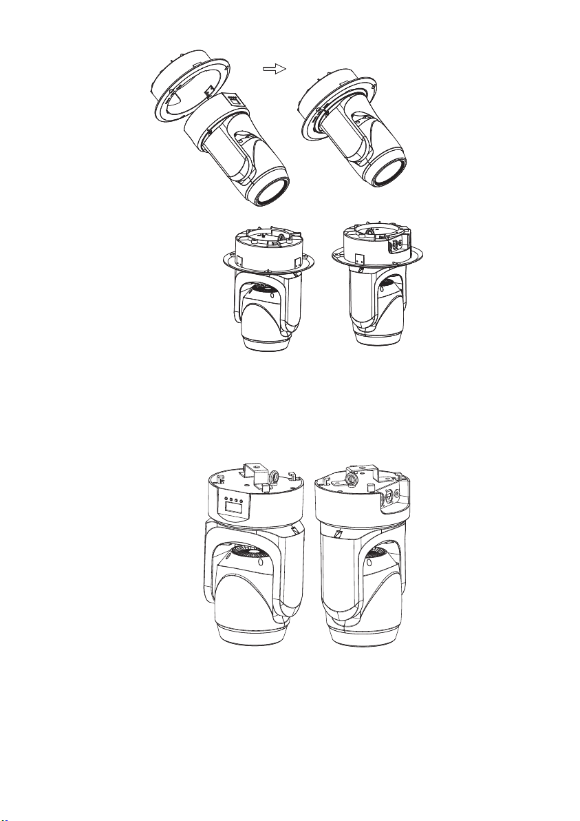
Requirements of embedded installation:
1. Drill a hole with diameter of 190mm on ceilling floor.
2. install embedded plate on ceiling floor, fix it with srews.
3. Hold light base and aim at the "unlock" point on the embedded plate.
4. Keep pushing up until the light base completely embedded in the
plate,clockwise rotate 15°.
5. To ensure safety,user should clamp the light tightly before releasing hands
in case of the light falling down.
6.The light base has hanging accessories, user can add the safety rope
hanger according to site situation.
Troubleshooting
Following are a few common problems that may occur during
operation.Here are some suggestions for easy troubleshootinge.
A. The fixture does not work,no light.
1. Check the connection of power and main fuse.
2. Make sure the mains voltage on the main connector.
3. Check the power LED.
B. Not responding to DMX controller.
1. DMX LED should be on.If not,check DMX connectors,cables to see if
link properly.
2. If the DMX LED is on and no response to the channel,check the
address settings and DMX polarity.
3. If you have intermittent DMX signal problems,check the pins on
connectors or on PCB of the fixture or the previous one.
4. Try to use another DMX controller.
5. Check if the DMX cables run near or run alongside to high voltage
cables that may cause damage or interference to DMX interface circuit.
C. Not response to the sound.
1. Make sure the fixture not receive DMX signal.
2. Check microphone to see if it is good by tapping the microphone.
D. One of the channels is not working well.
1. The stepper motor might be damaged or the cable connected to the PCB
is broken,
2. The motor’s drive IC on the PCB might be out of service.
Page 14
Embedded installation
Independent installation
Page 3

R:638nm 120mW
G:532nm 150mW
B:450nm 30mW
1. At last fixture, the DMX cable has to be terminated with a terminator
to reduce signal errors.Solder a 120-ohm 1/4W resistor between pin
2(DMX-) and pin 3(DMX+) into a 3-pin XLR-plugand plug it in the
DMX-output of the last fixture.
2. Connect the fixture together in a “daisy chain”by XLR plug cable from
the output of the fixture to the input of the next fixture.The cable
can’t be branched or split to a “Y”cable.
3. Inadequate or damaged cables,soldered joints or corroded connectors
can easily distort the signal and shut down the system.
The DMX output and input connectors are pass through to maintain
the DMX circuit when one of the units’power is disconnected.
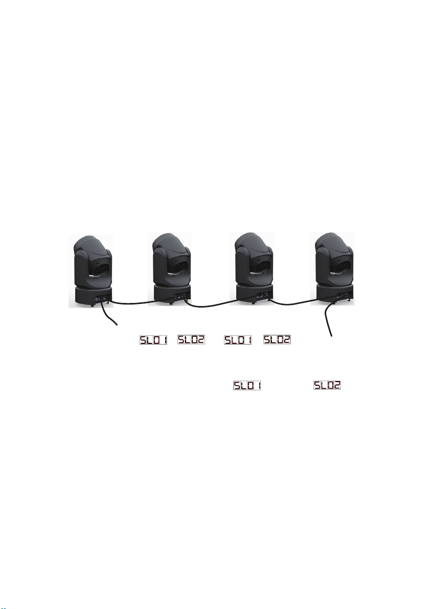
Master-slave Connection
Unit 1 Unit 2 Unit 3 Unit 4
set as master
set as slave set as slave
DMX OUTPUT
1. When there are multiple machines need to be connected, have to set
one of them as master and in the sound control mode or auto mode,
then set other machines as slave 1. or slave 2
2. At last fixture, the DMX cable has to be terminated with a terminator
to reduce signal errors.Solder a 120-ohm 1/4W resistor between pin
2(DMX-) and pin 3(DMX+) into a 3-pin XLR
plugand plug it in the
DMX-output of the last fixture.
3. Connect the fixture together in a “daisy chain”by XLR plug cable from
the output of the fixture to the input of the next fixture.The cable
can’t be branched or split to a “Y”cable.
4. Inadequate or damaged cables,soldered joints or corroded connectors
can easily distort the signal and shut down the system.
The DMX output and input connectors are pass through to maintain
the DMX circuit when one of the units’power is disconnected.
( or )
( or )
Page 13
Page 4
Sound/Auto-play/ILDA file/Playlist file/DMX /master slave
Standard Paking
Power Adapter*1,Hanging bracket*1,Screw*2,Instruction
manual*1,Ceiling plate(optional)
LS3000RGB
Input:AC 100-240V 50/60Hz
Output: DC 24V 2A
Te chn ical Specification
Model
Technical
RGB synthetic laser 300mW
Light source
Adapter
50WInput power
Control mode
DMX channel 20CH/22CH
Effect
Net weight 2.5 kg
Lightweight and flexible,Combined with ceiling plate
accessorie,Can be embedded in ceiling or wall mounting.
Horizontal angel: Pan angle is 540°
Vertical angel: Tilt angle is 180°
Fantastic night light effect,Great for bar, slow shake, club,
disco. Etc
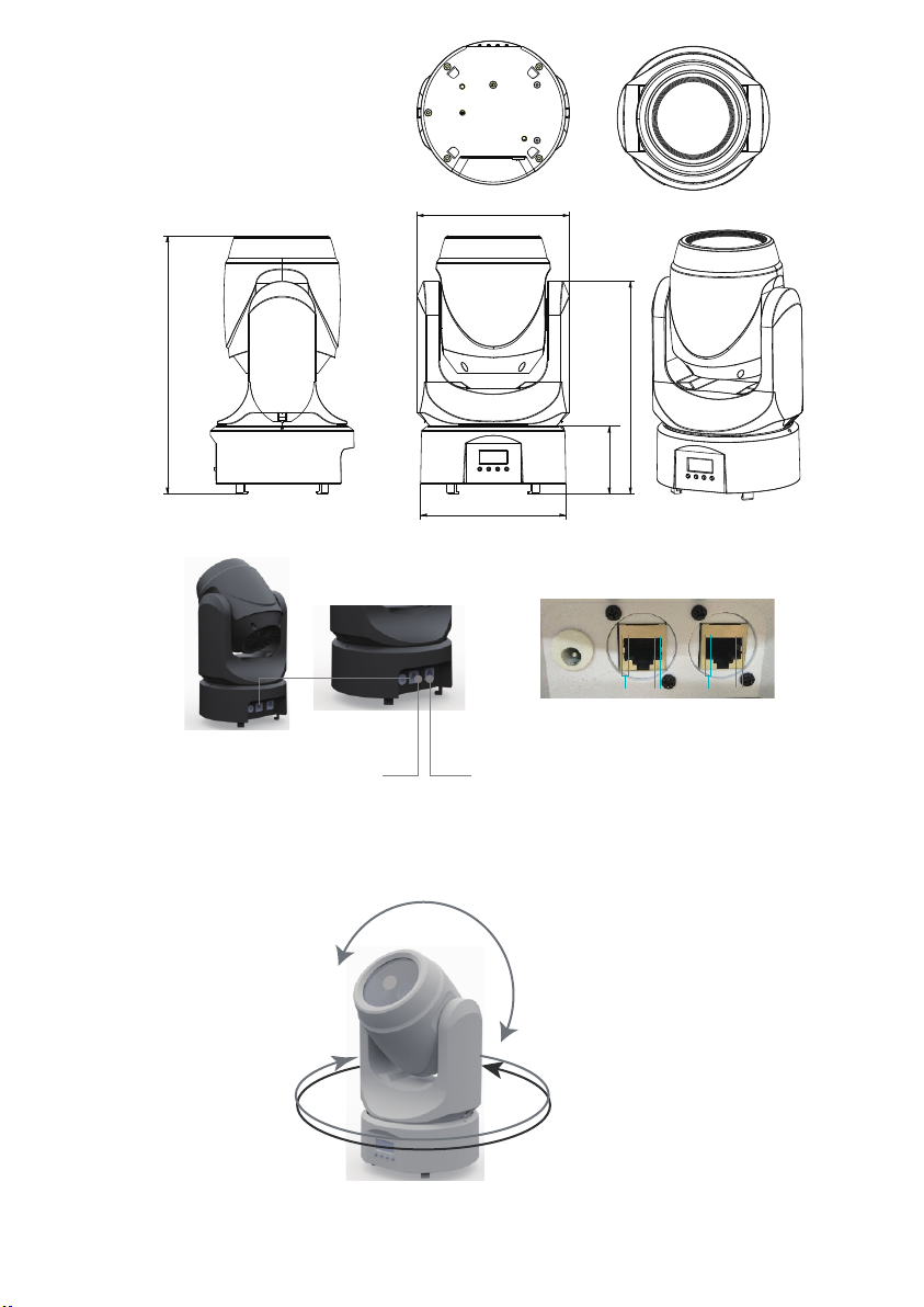
540°
180°
18 20 Speed/Sensentivity
000-255 Speed Slow-Fast (Auto and Porgramme
Mode in Effect)
000-255 Sound Sensentivity Less-Higher (Sound
Display in Effect)
000-049 Default phase(Digital menu set phase)
050-099 Phase setting 1
100-149
150-199
20 22 Reset 200-255 (Stay 5S) Lamp Reset
19 21 Laser phase setting Phase setting 2
Phase setting 3
Phase setting 4
200-255
Termination reduces signal errors and avoid signal transmission
problems and interference.It is always advisable to connect a
DMX terminal.(Resistance 120 ohm 1/4W) between pin2(DMX-)
AND pin3(DMX+) of the last fixture.
Unit 1
DMX Connection
Unit 2 Unit 3 Unit 4
Page 12
DMX 512 Controller
DMX OUTPUT
INPUT
INPUT
OUTPUT
OUTPUT
COMMON
12345678
12345678
+
-
GND
Page 5
DMX output DMX input
12345678 12345678
1 23 123
1.GND
2.+
3.-
Internet Connector
237.4
288
75.5
170
162
000-069
070-139
140-209
210-255
17 19 Function Choose
000-009 No Function
010-099 Auto Play(Laser Display Default Setting)
100-199 Sound Control Play
200-255 Prog ramme Mode Play(Laser Display
as TF list)
Auto Speed Setting
Channel 20
Channel 22
X Motor Forward
X Motor Reversion
Y Motor Forward
Y Motor Reversion
Digital Display Opening
In 60S, Digital Display Off
In 10S, Digital Display Off
In 30S, Digital Display Off
Press Cfrm to Factory
Default Setting
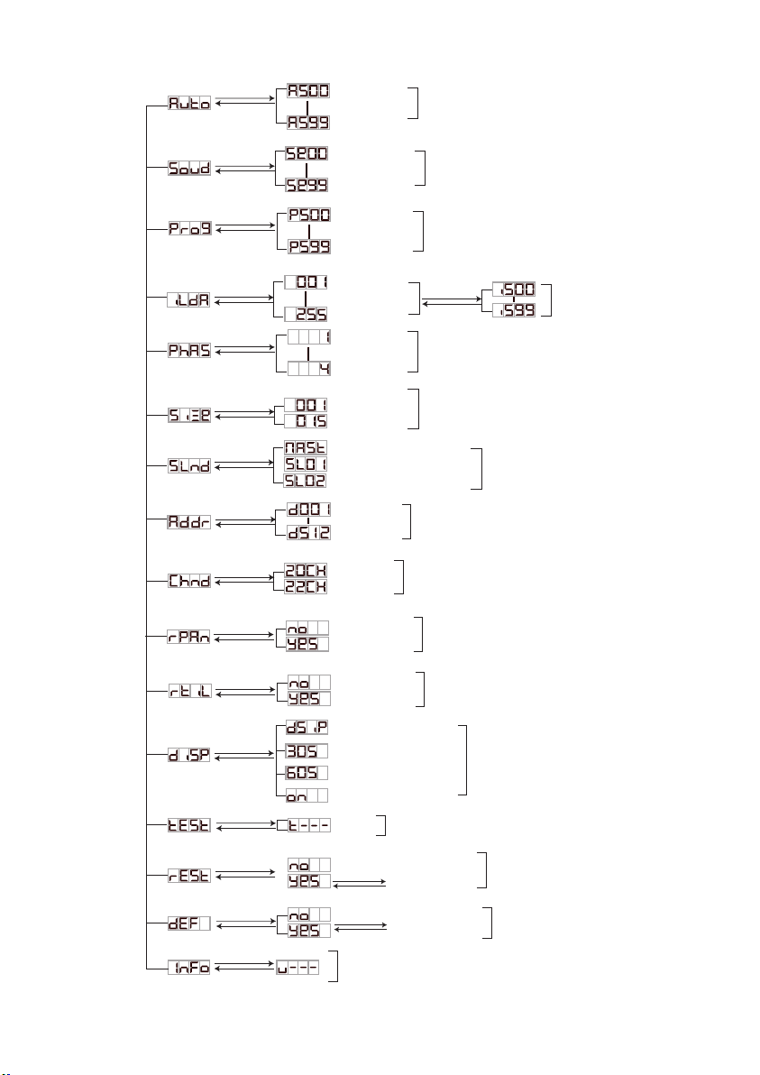
Auto
Sound
Dmx Channel Setting
X Motor Reversion Setting
Y Motor Reversion Setting
Reset
Display
Test
Testing
Press Cfrm to Reset
Ver
Default
ENTER
MENU
ENTER
MENU
ENTER
MENU
ENTER
MENU
ENTER
MENU
ENTER
MENU
ENTER
MENU
ENTER
MENU
ENTER
MENU
ENTER
MENU
ENTER
MENU
ENTER
MENU
ENTER
MENU
Sound Sensitivity
Setting
Programme Mode,
Auto Speed Setting Programme
DMX512 Setting
ENTER
MENU
ILDA Selection ILDA
ENTER
MENU 4 Phases Setting Phase Setting
Sizes Setting Laser Size Setting
ENTER
MENU
Master Mode
ENTER
MENU
Sl1 and Master in Synchronization
Sl2 Motor and Master Reversion Master-Slave Setting
DMX 001-512
ENTER
MENU
ENTER
MENU
Laser Rotation in
Middle
12
No Rotation
14
No Rotation
Auto Rotation Clockwise
Auto Roation Anticlockwise
Unchange
Mannual Adjust Drawing
000
001-150
151-255
000
001-180
181-217
218-255
000-001
002-149
150-255
15 17
011-200
Wave effect, fixed amplitude, slow speed----block
201-255
Wave effect, fixed speed, small amplitude----large
Normal Indication
Spot Display
Phase Display
Dot Display
000-018
019-037
038-056
057-075
076-094
095-113
114-132
133-151
152-170
209-227
16 18 Laser Colors
228-246
247-255
Laser Rotation with
Y Direction
11 13
Laser Drawing
13 15
000-010 No waves
14 16
Laser X Axis Wave
Laser Display Mode
Choose
171-189
190-208
Anually adjust the Y-axis rotation angle
Automatic rotation around the Y axis
Manually adjust the rotation angle
Automatic progressive subtraction cycle
Page 6
Menu Functio
Menu
Page 11
White
Red
Green
Blue
Yellow
Purple
Cyan
Red, green and blue Tri-color segmentation
Yellow blue purple Tri-color segmentation
White red green blue yellow purple blue
Seven-color segmentation
Red, green and blue Three-color flow
Yellow blue purple Three-color flow
White red green blue yellow purple blue
Seven-color flow
Voice-activated change to color
(need matching speed sensitivity channel)

Press the “MENU” button until the digital display ,Press “ENTER” to enter the
auto mode.Press the “UP”/“DOWN” button to adjust the speed of the auto mode.Speed
adjustment range is from to , is the slowest is the fastest.
Press “ENTER” to save the settings and exit the current menu to return to the previous
menu.
Press the “MENU” button until the digital display ,Press “ENTER” to enter the
Voice control model.Press the “UP”/“DOWN” button to adjust the speed of the Voice
control model.Speed adjustment range is from to , has the lowest
sensitivity and has the highest sensitivity.
Press “ENTER” to save the settings and exit the current menu to return to the previous
menu.
Press the “MENU” button until the digital display ,Press “ENTER” to enter the
Program list,Automatically loop the ILDA file on the playlist file,Press the “UP”/“DOWN”
button to adjust the speed of the Program list.Speed adjustment range is from -
, has the lowest sensitivity and has the highest sensitivity .
Press “ENTER” to save the settings and exit the current menu to return to the previous
menu.
Press the “MENU” button until the digital display ,Press “ENTER” to enter the
“ilad” document model.Press the “UP”/“DOWN” button to adjust the file rotation.Ilad file
selection adjustment range is .
Press “ENTER” to save the settings and exit the current menu to return to the previous
menu.
Press “ENTER” to save the settings and exit the current menu to return to the previous
menu.
Press the “MENU” button until the digital display ,Press “ENTER” to enter Phase
setting.Press the “UP”/“DOWN” button to adjust phase setting.The speed phase setting
is adjusted to - .
Press the “MENU” button until the digital display ,Press “ENTER” to enter Laser
size setting.Press the “UP”/“DOWN” button to adjust Laser size .The Laser size setting
is adjusted to - .The laser has the smallest size and the
laser has the largest size.
Press “ENTER” to save the settings and exit the current menu to return to the previous
menu.
setting is , .
lamp, others are slave lamps
The actual adjustment range is
determined by the number of ilda files in the TF card.
(Mannual Mode)
20
Channe
21
Channe
Function Value Percent/Setting
1 1 Pan 000-255 0-540°(8bit)
2 Pan Fine 000-255 (16bit)
2 3 Tilt 000-255 0-180°(8bit)
4 Tilt Fine 000-255 (16bit)
3 5 Pan/Tilt Speed
000-255 Fast to slow
4 6 Laser Mode
Choose
000-049 Cut-off Light
050-099
Sound (Controlled with Speed/Sensentivity channel)
100-149 Auto
150-199 prog model
200-249 ilda model
5 7 000-255 3 Values 1 GOBO (Mannual Mode)
Not Strobe
6 8
7
9
Laser Patterns X
Direction Movement
000-167 Laser gobo manually adjust the position
Laser gobo automatic circulating motion,from Left to right
Laser gobo automatic circulating motion,from
right to left
Laser gobo automatic circulating motion,right and left
Irregular jump
168-188
189-209
210-255
Default Patterns
Selection
ILDA Files Choose (ILDA Mode)
000-009
010-255 Strobe Slow-Fast (Mannual Mode)
Strobe
8 10
No Zoom
000-010
9 11
Laser Zoom
011-104
Auto Zoom+
Auto Zoom-
Recycle Zoom
No rotation
105-154
155-204
205-255
000
001-150
Mannual Zoom
151-255
Laser Rotation with
X Direction
10 12
000-255
250-255 Mannual Mode
000-167
168-188
189-209
210-255
Laser gobo Vertical manual adjust the position
Laser gobo automatic circulating motion,from
below to upper
Laser gobo automatic circulating motion,from
upper to below
Laser gobo automatic circulating motion,below and
lupper Irregular jump
Anually adjust the X-axis rotation angle
Automatic rotation around the X axis
Press “MENU”till screen show , press “ENTER”to master-slave setting, press
“UP”/“DOWN ”to adjust master-slave setting. Press “ENTER”to save setting.
Page 10
DMX channel function
Page 7
Instruction of Function
Auto model
Voice control model
Master-slave setting
Master-slave
and
: Master mode, several lamps connected togethre, there will be one lamp as master
Laser Patterns Y
Direction Movement
Program list mode
ILDA model
Phase setting
Laser size setting

Press “ENTER” to exist current menu and back to previouse manue.
: Slave mode 1, same setting as master lamp. Display as master.
: Slave mode 2, same settingas master lamp, x ray ,y ray run opposite to master
lamp. Partly LED color same as master lamp,partly difference.
Press the “MENU” button until the digital display ,Enter the test mode luminaire to
test each function in sequence.
Press the “menu” button to exit the test mode and return to the previous menu.
Press the “menu” button until the digital display , press the “enter” button to view
the information display.
If the luminaire is not equipped with a TF card, the digital prompt and .If
the light has a card, but without documents in the card,file format is incorrect,file storage
the path is in correct, digital display Prompt and .
Press“MENU” bottom till screen show , press “ENTER”to channel setting. Press
Channel Setting
press“MENU” bottom till screen show , press“ENTER”to adress setting, press
“UP”/“DOWN”to adjust MDX address. Press “ENTER”to save setting.
Press “ENTER” to exist current menu and back to previouse manue.
Adress Setting
The range of DMX address settingis -
“UP”/“DOWN”to adjust channel setting.Press “ENTER”to save setting.
Press “ENTER” to exist current menu and back to previouse manue.
press“MENU” bottom till screen show , Press“ENTER”to X-axis inversion setting.
Press“UP”/“DOWN”to adjust X-axis inversion setting.
Press “ENTER” to exist menu and back to up previouse manue.
Page 9
Reset
Press "MENU" key until the digital display , press "ENTER" key to enter the reset
setting, press "UP" / "DOWN"Key to adjust the reset setting.
Reset settings are and respectively
: Press ENTER to exit the current menu and return to the previous menu
: Press ENTER, the lamp is reset
Press "ENTER" to exit the current menu to return to the previous menu.
Restore the default settings
Press "MENU" key until the digital display , press "ENTER" key to enter restore
default settings, press "UP" /"DOWN" key to restore the default settings.
Restore default settings are and
:
Press ENTER to exit the current menu and return to the previous menu.
Press ENTER to restore the default setting
Press "ENTER" to exit the current menu to return to the previous menu.
The default factory values are as follows:
1. Auto model,speed is
2.Sound control on, voice sensitivity
4. The main and auxiliary modes are
5. The channel is set to
6.The address code is
7.X-axis positive, Y-axis positive
8.Digital display is positively lit
Information show
Page 8
Channel setting is and
X-axis inversion setting
X axis setting is and
: X axis positive
: X axis negative
Y-axis inversion setting
Press the "MENU" button until is displayed on the digital display,Press "ENTER" key
to enter the Y-axis to reverse setting, press "UP"/ "DOWN" key to adjust the y-axis inversion
setting
Y-axis inversion settings are and respectively
: Y-axis positive
: Y-axis reversed
Press "ENTER" to exit the current menu to return to the previouse menue.
Display setting
Press "MENU" key until the digital display , press "ENTER" key to enter the display
settings, press "UP" / "DOWN"
Key to adjust the display settings.
Display settings are , , and
: Digital display backward
: Displayed off after 30 seconds without pressing the button
: Displayed off after 60 seconds without pressing the button
: Digital display is steady
Press "MENU" to exit the current menu to return to the previous menu.
Test setup
Press "ENTER" to exit the current menu to return to the previouse menue.
3. The Laser size are
:

Press “ENTER” to exist current menu and back to previouse manue.
: Slave mode 1, same setting as master lamp. Display as master.
: Slave mode 2, same settingas master lamp, x ray ,y ray run opposite to master
lamp. Partly LED color same as master lamp,partly difference.
Press the “MENU” button until the digital display ,Enter the test mode luminaire to
test each function in sequence.
Press the “menu” button to exit the test mode and return to the previous menu.
Press the “menu” button until the digital display , press the “enter” button to view
the information display.
If the luminaire is not equipped with a TF card, the digital prompt and .If
the light has a card, but without documents in the card,file format is incorrect,file storage
the path is in correct, digital display Prompt and .
Press“MENU” bottom till screen show , press “ENTER”to channel setting. Press
Channel Setting
press“MENU” bottom till screen show , press“ENTER”to adress setting, press
“UP”/“DOWN”to adjust MDX address. Press “ENTER”to save setting.
Press “ENTER” to exist current menu and back to previouse manue.
Adress Setting
The range of DMX address settingis -
“UP”/“DOWN”to adjust channel setting.Press “ENTER”to save setting.
Press “ENTER” to exist current menu and back to previouse manue.
press“MENU” bottom till screen show , Press“ENTER”to X-axis inversion setting.
Press“UP”/“DOWN”to adjust X-axis inversion setting.
Press “ENTER” to exist menu and back to up previouse manue.
Page 9
Reset
Press "MENU" key until the digital display , press "ENTER" key to enter the reset
setting, press "UP" / "DOWN"Key to adjust the reset setting.
Reset settings are and respectively
: Press ENTER to exit the current menu and return to the previous menu
: Press ENTER, the lamp is reset
Press "ENTER" to exit the current menu to return to the previous menu.
Restore the default settings
Press "MENU" key until the digital display , press "ENTER" key to enter restore
default settings, press "UP" /"DOWN" key to restore the default settings.
Restore default settings are and
:
Press ENTER to exit the current menu and return to the previous menu.
Press ENTER to restore the default setting
Press "ENTER" to exit the current menu to return to the previous menu.
The default factory values are as follows:
1. Auto model,speed is
2.Sound control on, voice sensitivity
4. The main and auxiliary modes are
5. The channel is set to
6.The address code is
7.X-axis positive, Y-axis positive
8.Digital display is positively lit
Information show
Page 8
Channel setting is and
X-axis inversion setting
X axis setting is and
: X axis positive
: X axis negative
Y-axis inversion setting
Press the "MENU" button until is displayed on the digital display,Press "ENTER" key
to enter the Y-axis to reverse setting, press "UP"/ "DOWN" key to adjust the y-axis inversion
setting
Y-axis inversion settings are and respectively
: Y-axis positive
: Y-axis reversed
Press "ENTER" to exit the current menu to return to the previouse menue.
Display setting
Press "MENU" key until the digital display , press "ENTER" key to enter the display
settings, press "UP" / "DOWN"
Key to adjust the display settings.
Display settings are , , and
: Digital display backward
: Displayed off after 30 seconds without pressing the button
: Displayed off after 60 seconds without pressing the button
: Digital display is steady
Press "MENU" to exit the current menu to return to the previous menu.
Test setup
Press "ENTER" to exit the current menu to return to the previouse menue.
3. The Laser size are
:

Press the “MENU” button until the digital display ,Press “ENTER” to enter the
auto mode.Press the “UP”/“DOWN” button to adjust the speed of the auto mode.Speed
adjustment range is from to , is the slowest is the fastest.
Press “ENTER” to save the settings and exit the current menu to return to the previous
menu.
Press the “MENU” button until the digital display ,Press “ENTER” to enter the
Voice control model.Press the “UP”/“DOWN” button to adjust the speed of the Voice
control model.Speed adjustment range is from to , has the lowest
sensitivity and has the highest sensitivity.
Press “ENTER” to save the settings and exit the current menu to return to the previous
menu.
Press the “MENU” button until the digital display ,Press “ENTER” to enter the
Program list,Automatically loop the ILDA file on the playlist file,Press the “UP”/“DOWN”
button to adjust the speed of the Program list.Speed adjustment range is from -
, has the lowest sensitivity and has the highest sensitivity .
Press “ENTER” to save the settings and exit the current menu to return to the previous
menu.
Press the “MENU” button until the digital display ,Press “ENTER” to enter the
“ilad” document model.Press the “UP”/“DOWN” button to adjust the file rotation.Ilad file
selection adjustment range is .
Press “ENTER” to save the settings and exit the current menu to return to the previous
menu.
Press “ENTER” to save the settings and exit the current menu to return to the previous
menu.
Press the “MENU” button until the digital display ,Press “ENTER” to enter Phase
setting.Press the “UP”/“DOWN” button to adjust phase setting.The speed phase setting
is adjusted to - .
Press the “MENU” button until the digital display ,Press “ENTER” to enter Laser
size setting.Press the “UP”/“DOWN” button to adjust Laser size .The Laser size setting
is adjusted to - .The laser has the smallest size and the
laser has the largest size.
Press “ENTER” to save the settings and exit the current menu to return to the previous
menu.
setting is , .
lamp, others are slave lamps
The actual adjustment range is
determined by the number of ilda files in the TF card.
(Mannual Mode)
20
Channe
21
Channe
Function Value Percent/Setting
1 1 Pan 000-255 0-540°(8bit)
2 Pan Fine 000-255 (16bit)
2 3 Tilt 000-255 0-180°(8bit)
4 Tilt Fine 000-255 (16bit)
3 5 Pan/Tilt Speed
000-255 Fast to slow
4 6 Laser Mode
Choose
000-049 Cut-off Light
050-099
Sound (Controlled with Speed/Sensentivity channel)
100-149 Auto
150-199 prog model
200-249 ilda model
5 7 000-255 3 Values 1 GOBO (Mannual Mode)
Not Strobe
6 8
7
9
Laser Patterns X
Direction Movement
000-167 Laser gobo manually adjust the position
Laser gobo automatic circulating motion,from Left to right
Laser gobo automatic circulating motion,from
right to left
Laser gobo automatic circulating motion,right and left
Irregular jump
168-188
189-209
210-255
Default Patterns
Selection
ILDA Files Choose (ILDA Mode)
000-009
010-255 Strobe Slow-Fast (Mannual Mode)
Strobe
8 10
No Zoom
000-010
9 11
Laser Zoom
011-104
Auto Zoom+
Auto Zoom-
Recycle Zoom
No rotation
105-154
155-204
205-255
000
001-150
Mannual Zoom
151-255
Laser Rotation with
X Direction
10 12
000-255
250-255 Mannual Mode
000-167
168-188
189-209
210-255
Laser gobo Vertical manual adjust the position
Laser gobo automatic circulating motion,from
below to upper
Laser gobo automatic circulating motion,from
upper to below
Laser gobo automatic circulating motion,below and
lupper Irregular jump
Anually adjust the X-axis rotation angle
Automatic rotation around the X axis
Press “MENU”till screen show , press “ENTER”to master-slave setting, press
“UP”/“DOWN ”to adjust master-slave setting. Press “ENTER”to save setting.
Page 10
DMX channel function
Page 7
Instruction of Function
Auto model
Voice control model
Master-slave setting
Master-slave
and
: Master mode, several lamps connected togethre, there will be one lamp as master
Laser Patterns Y
Direction Movement
Program list mode
ILDA model
Phase setting
Laser size setting

000-069
070-139
140-209
210-255
17 19 Function Choose
000-009 No Function
010-099 Auto Play(Laser Display Default Setting)
100-199 Sound Control Play
200-255 Prog ramme Mode Play(Laser Display
as TF list)
Auto Speed Setting
Channel 20
Channel 22
X Motor Forward
X Motor Reversion
Y Motor Forward
Y Motor Reversion
Digital Display Opening
In 60S, Digital Display Off
In 10S, Digital Display Off
In 30S, Digital Display Off
Press Cfrm to Factory
Default Setting
Auto
Sound
Dmx Channel Setting
X Motor Reversion Setting
Y Motor Reversion Setting
Reset
Display
Test
Testing
Press Cfrm to Reset
Ver
Default
ENTER
MENU
ENTER
MENU
ENTER
MENU
ENTER
MENU
ENTER
MENU
ENTER
MENU
ENTER
MENU
ENTER
MENU
ENTER
MENU
ENTER
MENU
ENTER
MENU
ENTER
MENU
ENTER
MENU
Sound Sensitivity
Setting
Programme Mode,
Auto Speed Setting Programme
DMX512 Setting
ENTER
MENU
ILDA Selection ILDA
ENTER
MENU 4 Phases Setting Phase Setting
Sizes Setting Laser Size Setting
ENTER
MENU
Master Mode
ENTER
MENU
Sl1 and Master in Synchronization
Sl2 Motor and Master Reversion Master-Slave Setting
DMX 001-512
ENTER
MENU
ENTER
MENU
Laser Rotation in
Middle
12
No Rotation
14
No Rotation
Auto Rotation Clockwise
Auto Roation Anticlockwise
Unchange
Mannual Adjust Drawing
000
001-150
151-255
000
001-180
181-217
218-255
000-001
002-149
150-255
15 17
011-200
Wave effect, fixed amplitude, slow speed----block
201-255
Wave effect, fixed speed, small amplitude----large
Normal Indication
Spot Display
Phase Display
Dot Display
000-018
019-037
038-056
057-075
076-094
095-113
114-132
133-151
152-170
209-227
16 18 Laser Colors
228-246
247-255
Laser Rotation with
Y Direction
11 13
Laser Drawing
13 15
000-010 No waves
14 16
Laser X Axis Wave
Laser Display Mode
Choose
171-189
190-208
Anually adjust the Y-axis rotation angle
Automatic rotation around the Y axis
Manually adjust the rotation angle
Automatic progressive subtraction cycle
Page 6
Menu Functio
Menu
Page 11
White
Red
Green
Blue
Yellow
Purple
Cyan
Red, green and blue Tri-color segmentation
Yellow blue purple Tri-color segmentation
White red green blue yellow purple blue
Seven-color segmentation
Red, green and blue Three-color flow
Yellow blue purple Three-color flow
White red green blue yellow purple blue
Seven-color flow
Voice-activated change to color
(need matching speed sensitivity channel)

540°
180°
18 20 Speed/Sensentivity
000-255 Speed Slow-Fast (Auto and Porgramme
Mode in Effect)
000-255 Sound Sensentivity Less-Higher (Sound
Display in Effect)
000-049 Default phase(Digital menu set phase)
050-099 Phase setting 1
100-149
150-199
20 22 Reset 200-255 (Stay 5S) Lamp Reset
19 21 Laser phase setting Phase setting 2
Phase setting 3
Phase setting 4
200-255
Termination reduces signal errors and avoid signal transmission
problems and interference.It is always advisable to connect a
DMX terminal.(Resistance 120 ohm 1/4W) between pin2(DMX-)
AND pin3(DMX+) of the last fixture.
Unit 1
DMX Connection
Unit 2 Unit 3 Unit 4
Page 12
DMX 512 Controller
DMX OUTPUT
INPUT
INPUT
OUTPUT
OUTPUT
COMMON
12345678
12345678
+
-
GND
Page 5
DMX output DMX input
12345678 12345678
1 23 123
1.GND
2.+
3.-
Internet Connector
237.4
288
75.5
170
162
R:638nm 120mW
G:532nm 150mW
B:450nm 30mW
1. At last fixture, the DMX cable has to be terminated with a terminator
to reduce signal errors.Solder a 120-ohm 1/4W resistor between pin
2(DMX-) and pin 3(DMX+) into a 3-pin XLR-plugand plug it in the
DMX-output of the last fixture.
2. Connect the fixture together in a “daisy chain”by XLR plug cable from
the output of the fixture to the input of the next fixture.The cable
can’t be branched or split to a “Y”cable.
3. Inadequate or damaged cables,soldered joints or corroded connectors
can easily distort the signal and shut down the system.
The DMX output and input connectors are pass through to maintain
the DMX circuit when one of the units’power is disconnected.
Master-slave Connection
Unit 1 Unit 2 Unit 3 Unit 4
set as master
set as slave set as slave
DMX OUTPUT
1. When there are multiple machines need to be connected, have to set
one of them as master and in the sound control mode or auto mode,
then set other machines as slave 1. or slave 2
2. At last fixture, the DMX cable has to be terminated with a terminator
to reduce signal errors.Solder a 120-ohm 1/4W resistor between pin
2(DMX-) and pin 3(DMX+) into a 3-pin XLR
plugand plug it in the
DMX-output of the last fixture.
3. Connect the fixture together in a “daisy chain”by XLR plug cable from
the output of the fixture to the input of the next fixture.The cable
can’t be branched or split to a “Y”cable.
4. Inadequate or damaged cables,soldered joints or corroded connectors
can easily distort the signal and shut down the system.
The DMX output and input connectors are pass through to maintain
the DMX circuit when one of the units’power is disconnected.
( or )
( or )
Page 13
Page 4
Sound/Auto-play/ILDA file/Playlist file/DMX /master slave
Standard Paking
Power Adapter*1,Hanging bracket*1,Screw*2,Instruction
manual*1,Ceiling plate(optional)
LS3000RGB
Input:AC 100-240V 50/60Hz
Output: DC 24V 2A
Te chn ical Specification
Model
Technical
RGB synthetic laser 300mW
Light source
Adapter
50WInput power
Control mode
DMX channel 20CH/22CH
Effect
Net weight 2.5 kg
Lightweight and flexible,Combined with ceiling plate
accessorie,Can be embedded in ceiling or wall mounting.
Horizontal angel: Pan angle is 540°
Vertical angel: Tilt angle is 180°
Fantastic night light effect,Great for bar, slow shake, club,
disco. Etc

Troubleshooting
Following are a few common problems that may occur during
operation.Here are some suggestions for easy troubleshootinge.
A. The fixture does not work,no light.
1. Check the connection of power and main fuse.
2. Make sure the mains voltage on the main connector.
3. Check the power LED.
B. Not responding to DMX controller.
1. DMX LED should be on.If not,check DMX connectors,cables to see if
link properly.
2. If the DMX LED is on and no response to the channel,check the
address settings and DMX polarity.
3. If you have intermittent DMX signal problems,check the pins on
connectors or on PCB of the fixture or the previous one.
4. Try to use another DMX controller.
5. Check if the DMX cables run near or run alongside to high voltage
cables that may cause damage or interference to DMX interface circuit.
C. Not response to the sound.
1. Make sure the fixture not receive DMX signal.
2. Check microphone to see if it is good by tapping the microphone.
D. One of the channels is not working well.
1. The stepper motor might be damaged or the cable connected to the PCB
is broken,
2. The motor’s drive IC on the PCB might be out of service.
Page 14
Embedded installation
Independent installation
Page 3

TF card (including 16GB).
1. Make sure there is no flammable or explosive subjects within min 1.5
meter nearby the installation.
2.Before installation, please check and make sure the power supply
voltage meet request of the system.
3. Please check ventilation and fans or exhaust passages are cleared.
4. The equipment should be fixed firmly.
5. For security reasons, the appliance must be earthed.
Installation
Moving Laser*1 Use Manual*1 Power Cable*1
Power Adapter*1 Ring*1 Hanging bracket*1
Screw*2 Ceiling plate(optional)*1 TF card*1
TF card file description
1. This system only supports short file names, file names (including folder names) up to
8 bit file names and 3 bit extensions, file names and extensions by letters , numbers and
underscores. The file name cannot be more than 8 digits.no support Chinese characters,
or the file system can be not recognize.
2. TF card only special for TF file, cannot store with other files, support up to 255 ILDA files.
3. There should be a new folder in the TF card.There is a new.prg file (playlist file) and
some ILDA file under the new folder.Each newly added ILDA file should be added into to
the new.prg file.The format of the new.prg file is Use carriage return between each path,
The last path ending with two consecutive carriage returns.The name of the ilda file
corresponding to the path on the program list must same as add the name of the ilda
file.or the system cannot find the corresponding Ilda file.
Content on the list file new.prg TF card / new / path inside the file
4. The files supported by this system are standard ILDA format files, ie files with the
extension ild.
5.The file system of the TF card should be in FAT format and support up to 16GB
Inspection
In order to use the product securely and properly, please read the manual
before using and follow the instructions strictly to prevent personal safety
trouble and product damage caused by misuse.
Take care of the product, check the possibility of the product damage
caused by transportation and check all the listed items are present upon
receipt of the product.
The unit is with good performance and complete package when it is delivered.
The end-user of this unit should follow all the above instructionsand warnings.
Any damage caused by misuse,malfunction and problem caused by ignoring
the instructions are not included in the repair guarantess of the manufacturer
or dealers.
All the products manufactured by Big Dipper Laser Science and Technology
CO.,Ltd have anti-fake logo.Please check the anti-fake logo to make sure it’s
original to protect you.The anti-fake logo is on the bottom of product.
Page 15
Declare
Page 2
Requirements of embedded installation:
1. Drill a hole with diameter of 190mm on ceilling floor.
2. install embedded plate on ceiling floor, fix it with srews.
3. Hold light base and aim at the "unlock" point on the embedded plate.
4. Keep pushing up until the light base completely embedded in the
plate,clockwise rotate 15°.
5. To ensure safety,user should clamp the light tightly before releasing hands
in case of the light falling down.
6.The light base has hanging accessories, user can add the safety rope
hanger according to site situation.

Product warranty card
Please fill in the following content properly future maintenance.
Accordingly, for your each purchase of our systems wehave archive
Serial number and parameters for future reference.
Attention
1. Do not look directly at the bulb while the light is on.
Page 1
2.Follow the instructions. Do not disassemble the unit by yourself. Please
contact the skilled peoplein the event of aoperating problem.
3.The unit shallbeinstalled by professionals.
4.Place the unit away from the strobe light.
5.Keep the unit dry. Do not expose the unit to rain, moisture or dust.
Waterproof protection is needed when the unit is exposed outdoors.
6.Do not touch the unit and pull the power cable with wet hand.
7.Do not turn on or off the unit frequently. Otherwise, the service time will
be affected. Besides, keeping working for a long time should be avoided.
8.Fixed installation to prevent the unit from strong vibration or shock.
9.Prevent foreign objects from entering the unit to avoid malfunction.
10.Keep the distance between the unit and the objects in the lighting
50CM at least.
11.Do not connect the power cable or turn on the light before
installation.
12.Make sure the plug has been wired up properly before being powered
on.
13.Use the original shake-proof packing for re-transportation.
14.This symbol indicates separate collection of electronics and
electronic equipment.
The Company reserves the right to interpret the above terms.
1
3
LED Moving Beam After Sales Service
Testing: warranty: non-warranty:
Mode: Serial No.:
Distributor: Address:
Tel:
About Product Warranty
.Any product buy from our company (or authorized agent), which
used properly,and with this card, can have 1 year warranty for Lights,
mechanical parts, electronic parts. If out of the warranty situation,
we can provide the paid maintenance service.
2.The warranty is no longer valid in the following situations:
* Warranty cards and products have no serial numbers.。
* Product is damaged or show significant signs of self-disassembly.
*Any unauthorized modification (removal or replacement)
made to product or it?s components.
*Improper or excessive use of inappropriate repairs which result
in a repair failure or injury。
* Did not follow instructions or use in an environment not suitable
for product..
*Product damage caused by strong impact
*The warranty cannot be extended if the product as been serviced
*Light Source normal degradation
*Warranty card must be filled out with receipt of purchasing in order
for the warranty to be valid.
*Product is damaged due to abnormal voltage or caused by
other accidents (ex. Natural disasters).
.The Company reserves the right to interpret the provisions above.
The content of these articles is subject to change without notice!
LS3000RGB User Manual

Model: LS3000RGB
Please read the manual carefully before using
Moving Laser
User Manual
201830478508.1
Table of contents
Other BETOPPER Light Fixture manuals

Popular Light Fixture manuals by other brands


American DJ
American DJ Fusion Scan 250 User instructions

Sonifex
Sonifex SignalLED Series Handbook

Whelen Engineering Company
Whelen Engineering Company LFL Liberty Mini Edge installation guide

Chauvet
Chauvet Vue VI user manual

BEKA Schreder
BEKA Schreder LEDBAY-MIDI quick start guide

Cooper Lighting Solutions
Cooper Lighting Solutions B95 LED installation instructions

Lightolier
Lightolier STA 1'x4' 1 LAMP specification

Fulham
Fulham Thoroled TKT120013RD 01 Series installation instructions

LSI
LSI BPM Series installation instructions

Philips
Philips CDB2SPF228 specification

Larson Electronics
Larson Electronics LEDWP-600E-E2E-10C quick start guide

HEISSNER
HEISSNER SMART LIGHTS L433-00 Instructions for use