Fulham Thoroled TKT120013RD 01 Series User manual

LED LIGHT ENGINE APPLICATION PROGRAM
MANUAL FOR LED LIGHT ENGINE KIT INSTALLATION
Address: 12705 South Van Ness Ave., Hawthorne, CA 90250 · Telephone: 1-323-599-5000 · Fax: 1-323-754-9060 · E-mail: LEDretrofit@fulham.com · Website: www.fulham.com
01/14/16 LED 7” Engine, Rev D Page 1
INSTALLATION INSTRUCTIONS
LED Light Engine Kit Model: 7” Round Engine
Disclaimer: The driver pictured above is the 0-10V Dimming version. The
Triac Dimming driver does not have the gray and purple wires.
120V:TRIACDIMMING
TKT120013RDxx‐01
TKT120013RDxx‐11
TKT120011RDxx‐01
TKT120011RDxx‐11
TKT120013RDxx‐02
TKT120013RDxx‐12
TKT120011RDxx‐02
TKT120011RDxx‐12
UNV(120V‐277V):0‐10VDIMMING
TKMUNV013RDxx‐01
TKMUNV013RDxx‐11
TKMUNV011RDxx‐01
TKMUNV011RDxx‐11
TKMUNV013RDxx‐02
TKMUNV013RDxx‐12
TKMUNV011RDxx‐02
TKMUNV011RDxx‐12

LED LIGHT ENGINE APPLICATION PROGRAM
MANUAL FOR LED LIGHT ENGINE KIT INSTALLATION
Address: 12705 South Van Ness Ave., Hawthorne, CA 90250 · Telephone: 1-323-599-5000 · Fax: 1-323-754-9060 · E-mail: LEDretrofit@fulham.com · Website: www.fulham.com
01/14/16 LED 7” Engine, Rev D Page 2
Tool # Description QTY
1 11/32” Nut Driver 1
2 3/16” Drill Bit 1
3 Power Drill 1
4 Phillips Drill Bit (P2) 1
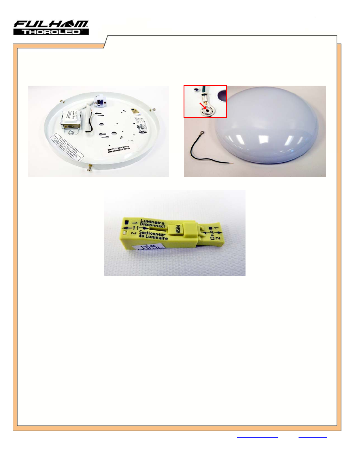
KeeptheOriginalDiffuser.
Removealltheremaining
originalfixtureparts,hardware,
andlampinordertobeginthe
retrofit.
Illustration 1: Minimum Original Luminaire Dimensions
Mfr: Lamar Li
g
htin
g
–
Model: CDW11311PN1SW
ThisLEDEngineKitcanretrofitanyluminairewithadiameter/heightgreaterorequaltotheminimum
dimensionsshownabove.
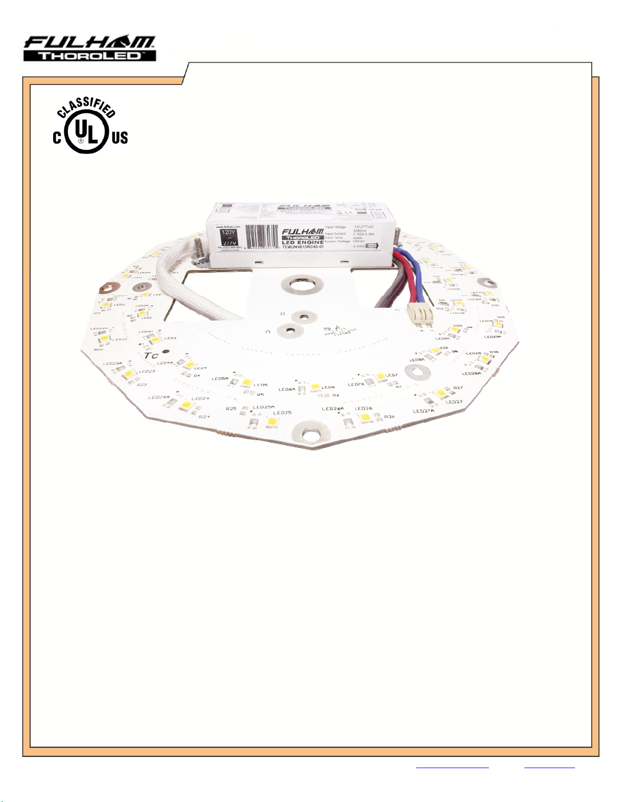
ThisLEDEngineKitcanbeusedwithluminairessimilartotheoneillustratedabove.
3.25”
Dia.=ø11”
Dia.=ø10”
1. “THIS PRODUCT MUST BE INSTALLED IN ACCORDANCE WITH THE APPLICABLE INSTALLATION CODE BY A PERSON
FAMILIAR WITH THE CONSTRUCTION AND OPERATION OF THE PRODUCT AND THE HAZARDS INVOLVED.”
2. "WARNING - Risk of fire or electric shock. LED Retrofit kit installation requires knowledge of luminaires electrical systems. If not
qualified, do not attempt installation. Contact a qualified electrician.”
3. "WARNING - Risk of fire or electric shock. Install this kit only in the luminaries that has the construction features and dimensions shown in
the photographs and/or drawings."
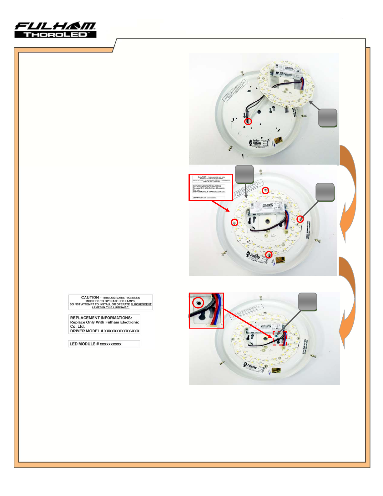
4. "WARNING - To prevent wiring damage or abrasion, do not expose wiring to edges of sheet metal or other sharp objects."
5. "WARNING –Risk of fire or electric shock. Luminaire wiring and electrical parts may be damaged when drilling for installation of LED
retrofit kit. Check for enclosed wiring and components."
6. “Please make sure the grounding conductor of the luminaire is properly secured to the Branch Circuit Grounding conductor. “
7. “CAUTION – RISK OF FIRE. CONSULT A QUALIFIED ELECTRICIAN TO ENSURE CORRECT BRANCH CIRCUIT
CONDUCTOR.”
8. “The assembly of this LED retrofit should be performed by a licensed electrician or equivalent as State or Provincial Codes and Laws
dictate.”
9. “WARNING – RISK OF FIRE OR ELECTRIC SHOCK. DO NOT ALTER, RELOCATE, OR REMOVE WIRING, LAMPHOLDERS,
POWER SUPPLY, OR ANY OTHER ELECTRICAL COMPONENT.”
10. “THE RETROFIT KIT IS ACCEPTED AS A COMPONENT OF A LUMINAIRE WHERE THE SUITABILITY OF THE COMBINATION
SHALL BE DETERMINED BY CSA OR AUTHORITIES HAVING JURISDICTION."
1.0 INSTALLATION INSTRUCTION WARNINGS
Tool #1 Tool #2 Tool #3
4.0 Required Tools (Not Included)
2.0 Minimum Original Luminaire Dimensions
Tool #4
3.0 Intended Use

LED LIGHT ENGINE APPLICATION PROGRAM
MANUAL FOR LED LIGHT ENGINE KIT INSTALLATION
Address: 12705 South Van Ness Ave., Hawthorne, CA 90250 · Telephone: 1-323-599-5000 · Fax: 1-323-754-9060 · E-mail: LEDretrofit@fulham.com · Website: www.fulham.com
01/14/16 LED 7” Engine, Rev D Page 3
ITEMDESCRIPTIONQTY
A.LEDEngine(IncludesLEDModuleandLEDDriver)1
B.6‐20X3/8”PanHeadDrillingScrews4
C.8‐32X1‐4”GroundGreenMachineScrew1
D.#8ExternalToothLockWasher1
E.8‐32HexNut1
LED Engine Retrofit Kit Consist of:
LED Engine Retrofit
Kit LED Engine: QTY Hardware: QTY
TKT120013RDxx-01 TET120013RDxx-01 1 TLC-HW02 1
TKT120013RDxx-11 TET120013RDxx-11 1 TLC-HW02 1
TKT120011RDxx-01 TET120011RDxx-01 1 TLC-HW02 1
TKT120011RDxx-11 TET120011RDxx-11 1 TLC-HW02 1
TKT120013RDxx-02 TET120013RDxx-02 1 TLC-HW02 1
TKT120013RDxx-12 TET120013RDxx-12 1 TLC-HW02 1
TKT120011RDxx-02 TET120011RDxx-02 1 TLC-HW02 1
TKT120011RDxx-12 TET120011RDxx-12 1 TLC-HW02 1
TKMUNV013RDxx-01 TEMUNV013RDxx-01 1 TLC-HW02 1
TKMUNV013RDxx-11 TEMUNV013RDxx-11 1 TLC-HW02 1
TKMUNV011RDxx-01 TEMUNV011RDxx-01 1 TLC-HW02 1
TKMUNV011RDxx-11 TEMUNV011RDxx-11 1 TLC-HW02 1
TKMUNV013RDxx-02 TEMUNV013RDxx-02 1 TLC-HW02 1
TKMUNV013RDxx-12 TEMUNV013RDxx-12 1 TLC-HW02 1
TKMUNV011RDxx-02 TEMUNV011RDxx-02 1 TLC-HW02 1
TKMUNV011RDxx-12 TEMUNV011RDxx-12 1 TLC-HW02 1
Recommended, but not included in the kit: Wire Nuts (Not Included)
Warning: Disconnect power when servicing fixture.
5.0 Included Components
Picture A: 7” LED Light Engine Kit
AB
C
D
E
NOTE: “XX” represents desired Kelvin Temperature. (Ex: 40: 4000K 50:5000K)

LED LIGHT ENGINE APPLICATION PROGRAM
MANUAL FOR LED LIGHT ENGINE KIT INSTALLATION
Address: 12705 South Van Ness Ave., Hawthorne, CA 90250 · Telephone: 1-323-599-5000 · Fax: 1-323-754-9060 · E-mail: LEDretrofit@fulham.com · Website: www.fulham.com
01/14/16 LED 7” Engine, Rev D Page 4
Picture B: Original Luminaire Housing
Original Luminaire Disassembly:
1. Remove all hardware, Insulation (if available) and original electronic components from the luminaire. See Picture B.
2. Parts to be kept include:
Original Luminaire Housing
Original Diffuser (See Picture C)
Grounding Cable (Green wire) (See Picture C). Rivet will need to be removed in order to use the Ground Cable.
Original Connector (If available) if not, use wire nuts for input connection. (See Picture D)
Picture C: Ori
g
inal Diffuser and
g
round cable
Picture D: Original Connector
6.0 Original Luminaire
Warning: Disconnect power when servicing fixture.

LED LIGHT ENGINE APPLICATION PROGRAM
MANUAL FOR LED LIGHT ENGINE KIT INSTALLATION
Address: 12705 South Van Ness Ave., Hawthorne, CA 90250 · Telephone: 1-323-599-5000 · Fax: 1-323-754-9060 · E-mail: LEDretrofit@fulham.com · Website: www.fulham.com
01/14/16 LED 7” Engine, Rev D Page 5
Picture#1
Picture#2
1. PasstheLEDEngine(Part:A)input
powerwiresanddimmingwires(if
available)throughtheluminairewire
hole.SeePicture#1.
NOTE:PleaseDONOTremoveanyoftheoriginal
labelsintheluminaire
2. AligntheLEDEngine(Part:A)center
holetotheluminairecenterhole.See
Picture#2.
NOTE:Makesurethekeyholes/mountingholesarenot
blocked
3. SecuretheLEDEngine(Part:A)tothe
luminairehousingbyusingthe6‐20x
3/8”DrillingScrews(Part:B).See
Picture#2.
4. Placetheprovidedlabelsintheouter
spaceoftheluminaireaftertheLED
engineinstallationhasbeen
completed.Labelsmustbevisible.See
picture#2andIllustration2
5. Drilla3/16”holeintheshown
location(arrow).Seepicture#3.
6. Insertthe8‐32x3/8”GroundGreen
MachineScrew(Part:C)throughthe
luminairepre‐drilled3/16”hole.See
Picture#3.
7.0 Retrofit Kit Assembly (7” Round)
Warning: Disconnect power when servicing fixture.
Picture#3
B
Illustration2
A
C
A

LED LIGHT ENGINE APPLICATION PROGRAM
MANUAL FOR LED LIGHT ENGINE KIT INSTALLATION
Address: 12705 South Van Ness Ave., Hawthorne, CA 90250 · Telephone: 1-323-599-5000 · Fax: 1-323-754-9060 · E-mail: LEDretrofit@fulham.com · Website: www.fulham.com
01/14/16 LED 7” Engine, Rev D Page 6
7. Ontherearsideoftheluminaire,
securethegroundingcableby
passingthealreadyinserted8‐32x
3/8”GroundGreenMachineScrew
(Part:C)inthefollowingorder:
8. Seethesectionbelow“Connecting
PowertotheLEDSystem”forproper
connectionsteps.
9. Mounttheluminairetotheceilingby
usingthethreadedstemandnut
(arrow)orthekeyholes(circles).See
picture#5.
10. Re‐attachandsecurethelenstothe
luminaire.SeePicture#6.
Picture#4
Picture#6
7.1 Retrofit Kit Assembly (7” Round)
Warning: Disconnect power when servicing fixture.
Warranty
Please see our warranty policy on LED system.
8.0 Warranty and Contact Information
WARNING:Groundscrewassemblyshouldnotbetorque
downover14lb‐in,anyhigherthan14lb‐inwillresultof
stripingthe8‐32x3/8”GroundGreenMachineScrew
(Part:C).
Picture#5
Connecting power to the LED System:
1) Connect the copper wire (Ground) from the luminaire housing to the ground wire (Ground) that is being fed by
the power source. Connect these two wires by using a 16-18 AWG Gauge Wire Nut.
2) Connect the white wire (Neutral) from the LED Engine (Part: A) to the white wire (Neutral) that is being fed by
the power source. Connect these two wires by using a 16-18 AWG Gauge Wire Nut.
3) Connect the black wire (Line) from the LED Engine (Part: A) to the black wire (Line) being fed by the power
source. Connect these two wires by using a 16-18 AWG Gauge Wire Nut.
D
E
C
IMPORTANT:Afterinstallationofgroundwirecheckfor
groundingconnectiontotheluminairehousing.
A. 8‐32ExternalToothLockWasher(Part:D)
B. GroundCable
C. 8‐32HexNut(Part:E)
This manual suits for next models
15
Table of contents
Other Fulham Light Fixture manuals