Signtex Moonlite LED MHE Series Manual

Wet Location
Series MHE-RE
Moonlite LED™
Emergency & Security Light
Installation Instructions & Users Manual
REV 8.17.04
SURFACE BRACKET TOP MOUNT RECESSED J-BOX
Fig. 1
1. Disconnect AC power before servicing.
2. Refer to wiring diagram for proper connections.
3. All servicing should be performed by qualified personnel.
4. Consult your local building code for approved wiring and
installation.
5. Do not use this equipment for other than intended use.
6. Do not let power cords touch hot surfaces.
7. Mount and secure the fixture at a location and height
to avoid ready access and tampering by unauthorized
persons.
8. The use of accessory equipment is not recommended by
the manufacturer and may cause an unsafe condition.
9. Suitable for wet locations. See product label for temperature
limitations.
IMPORTANT SAFEGUARDS READ AND FOLLOW ALL SAFETY INSTRUCTIONS
SAVE THESE INSTRUCTIONS
CEILING
BRACKET
LAMP PLUG
(SUPPLIED)
GASKET
LAMP ASSBY
PIGTAIL
(SUPPLIED)
(2) 8-32 X 3/8"
HEX HD SST
(2) 8-32 X 1"
BR
EM Lighting Only
LAMP PLUG
(SUPPLIED)
J BOX
4" X 4"
B
B
24 VDC INPUT
CIRCUIT
24 VDC OUTPUT
CIRCUIT
B
B
B
Y
Y
Y
Y
R
R
R
R
R
BL
BL
BL
BL
Normal On Lighting Option
PIGTAIL WITH
SPLITTER
(SUPPLIED)
R
BBR
B
24 VDC INPUT
CIRCUIT
24 VDC OUTPUT
CIRCUIT
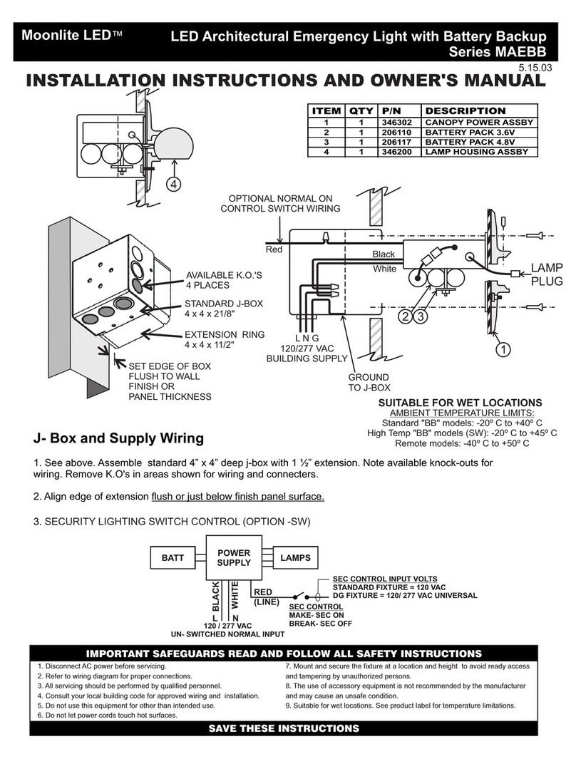
1. See Fig 1 and wiring details for EM Lighting Only, and Normal On Lighting Option. Identify mount position and install
4” x 4” J-Box. Route 24VDC wiring IN/OUT as shown and connect pigtail (supplied) with lamp plug. Connect Pigtail
RED +24V power input circuit and Pigtail RED -24V wire to COMMON NEGATIVE -24V power input circuit with
standard wire nuts.
2. Remove Lamp Assembly from bracket, place gasket in position on bracket canopy plate and route lamp plug through
gasket. Install (2) #8-32 screws and secure bracket in position. Ensure that gasket is in place correctly and tighten screws
evenly.
3. Connect lamp plug from Lamp Assembly and push connector and extra wire cable through gasket into J-Box. Install (4)
Hex Hd SST screws to secure Lamp Assembly into bracket.
CHECK CONNECTIONS BEFORE SUPPLYING POWER :
REVERSE POLARITY WILL PERMANENTLY DAMAGE FIXTURE
4. Supply 24VDC power from central battery or normal on/security power system to check lamp operation.
COLOR KEYS
24V TERMINALS FROM BATTERY PANEL
B= BLACK:COMMON: 12/24 VDC NEG -
Y= YELLOW: EXITS/CVRE: 12/24 VDC POS +
R= RED: EMERGENCY: 24VDC POS +
BL= BLUE: NORMAL ON LIGHTING (NOL): 24 VDC POS +
24V INPUT TO MHE LAMP ASSEMBLY
R = RED: 24VDC POS+
B = BLACK: COMMON 24VDC NEG-
Wet Location
Series MHE-RE
Moonlite LED™
Emergency & Security Light
CEILING
BRACKET
SPLITTER
(SUPPLIED)
BUSHING
CONDUIT
EM OPERATION ONLY
EM & NORMAL OPERATION ONLY
CONDUIT
LAMP CABLE
LIQUID TIGHT
OUTLET BOX
G
24 VDC INPUT
CIRCUIT
24 VDC OUTPUT
CIRCUIT
B
G
G
W
W
R
W
R
R
B
B
LIQUID TIGHT
OUTLET BOX
G
24 VDC INPUT
CIRCUIT
24 VDC OUTPUT
CIRCUIT
W
G
W
W
R
B
R
B
B
12" MAX
-2-
SURFACE BRACKET TOP MOUNT WITH EXTERNAL J-BOX
SURFACE HOUSING TOP MOUNT WITH EXTERNAL J-BOX
G
G
GR
R
R
B
B
1. See Fig 2 and wiring details for EM Lighting Only, and Normal On Lighting Option. Identify
mount position and install 4” x 4” LIQUID TIGHT J-Box near to fixture. Route 24 VDC wiring
IN/OUT as shown and connect pigtail (supplied) with lamp plug.
2. Install screw anchors in mounting surface for (4) #8-32 screws to match holes provided in
Bracket or Housing.
3. Remove Lamp Assembly and install (4) #8-32 screws to secure Bracket or Housing in position.
4. Secure lamp assembly to bracket with screws provided and route lamp cable through opening
in end of bracket. Insert lamp cable through liquid tight bushing into LIQUID TIGHT j-box.
5. Connect WHITE +24V lamp wire to POSITIVE +24V power input circuit and BLACK -24V lamp
wire to COMMON NEGATIVE -24V power input circuit with standard wire nuts.
CHECK CONNECTIONS BEFORE SUPPLYING POWER :
REVERSE POLARITY WILL PERMANENTLY DAMAGE FIXTURE
6. Supply 24VDC power from central battery or normal on/security power system to check lamp
operation.
LAMP
ASSBY
LAMP
ASSBY
(2) 8-32 X 3/8"
HEX HD SST
Fig. 2
COVER
BUSHING
8”
12" MAX
CEILING
LAMP
HOUSING
REV 8.17.04

Wet Location
Series MHE-RE
Moonlite LED™
Emergency & Security Light
-3-
Fig. 3. RECESSED MOUNT- WIRING
1. Route 24VDC IN/OUT wiring from CBS system into Housing.
2. Connect wiring with standard wire nuts to the supplied wiring pigtail, as shown. For emergency lighting
operation only, connect RED and GREEN; for normally ON/security lighting operation, connect RED,
GREEN and BLACK. (WHITE wire is passed through and not connected to this fixture).
3. Connect lamp plug and install lamp assembly with (4) #8 screws. Attach Trim Plate with (2) color- matched
#8-32 screws as shown. Ensure gasket is properly seated on flat surface. Use silicone on outer edge if
surface is rough.
4. Supply 24 VDC power from Central Battery System to check lamp operation.
POLARIZED
LAMP
CONNECTOR
LAMP
ASSBY
TRIM PLATE
FRAMING (BY OTHERS)
GASKET
24 VDC
OUTPUT
24 VDC
INPUT
BB
W
G
R
B
W
G
R
WG R
CEILING
WIRING FOR EM OPERATION ONLY
PIGTAIL
(SUPPLIED)
24 VDC
OUTPUT
CEILING
B
W
G
R
BWG R
KEY
G= GREEN: COMMON: 24 VDC NEG -
W= WHITE: EXITS: 12-24 VDC POS +
R= RED: EMERGENCY: 24VDC POS +
B= BLACK: NORMAL ON LIGHTING
(NOL): 24 VDC POS +
WIRING FOR EM & NORMAL ON OPERATION
PIGTAIL
(SUPPLIED)
24 VDC
INPUT
B
W
G
R
REV 8.17.04

Wet Location
Series MHE-RE
Moonlite LED™
Emergency & Security Light
-4-
220 VFW Avenue, Grasonville, MD 21638
TEL: (410) 827-8300 Fax:(410)827- 8866
sales@signtexinc.com www.signtexinc.com
Signtex Inc
LIGHTING
14 1/2”
24"-48"
T-BAR T-BAR
ROTATE B-CLIPS
90° TO FIT BAR
HANGERS AS
REQUIRED
HANGER
ALTERNATE
POSITION
CENTERED CUTOUT
3 3/8”
12-48"
Fig. 4. RECESSED MOUNT: T-BAR CEILING
MOUNT BRACKET
(2) SUPPLIED
B-CLIP 4 REQD.
BACK BOX
For T-Bar installations, rotate side bracket clips as required to fit T-Bar
hangers. For masonry ceilings, attach side brackets to framing.
MOUNT BRACKET 4 SUPPLIED
B-CLIP (4) SUPPLIED
DROPWIRES
BAR HANGER
(SUPPLIED
BY OTHERS)
CEILING
14 1/2””
Install Housing in ceiling using
supplied end brackets with B-
Clips to framing or hanger bars
(supplied by others). Long
edges of Housing should be
flush or just below finished
panel surface.
7/8" K.O. 2 PLCS
CEILING
MOUNT BRACKET
SCREW: (4) SUPPLIED
B-CLIP
3 3/8”
REV 8.17.04
This manual suits for next models
1
Other Signtex Light Fixture manuals