Beveler USA B15 User manual

1
MANUAL BEVELLING AND
DEBURRING SYSTEM B15
ELECTRA
Ord. no. 25250
Operation manual for the device
SUBJECT TO CHANGE

2
Contents:
General information 3
Machine description B15 AIR 3
Identification data 4
Tests 4
Warranties 5
Safety regulations 5
Technical specifications 6
Accessories 7
Machine equipment 7
Control elements B15 AIR 8
Use 9
Setting the removal size 9
Bevelling 11
Bevel angle and shape change. Milling head replacement 12
Replacement of indexable inserts 13
Maintenance and operation 14
Spare parts 14
List of spare parts 15
Read the operation manual carefully prior to use

3
1. General information
Thank you for purchasing one of our machines, and we hope that you will be fully satisfied.
This guide provides instructions for the installation, adjustment, operation and
maintenance of the machine B15 ELECTRA in compliance with valid safety standards.
The information and data contained in this document subject to changes due to
further improvement of machinery. To eliminate any doubts, when differences are
detected, please contact N.KO Machines.
Never perform any operation on the machine before you read the instructions in the
manual and understand them. Major part of accidents that happen in the workplace are
due to the fact that the guidelines and recommendations contained in the manual are
not complied with.
The graphic symbols used in the manual are intended to emphasize the important
information regarding the safety and operation of the machine.
Attention :
Information important for the personal safety of the operating staff.
Important:
Instruction that needs to be observed to ensure the proper function of the machine.
2. Machine description B15 ELECTRA
Machine B15 ELECTRA is designed solely for the activities below:
B15 ELECTRA is designed solely for bevelling and fetch fettling of metal materials in the
workshop or in the production hall.
This includes manual and manually managed machine. The main feature of the machine
is the ability to machine flat and shaped workpieces, openings, and tubes. The
machining angle can be changed by replacing the milling head. B15 ELECTRA can
perform also the workpiece edge rounding. This application also requires a special tool,
see the text below.
Use the machine in the environment protected from rain, snow, and other adverse
weather conditions.

4
3. Identification data and CE Declaration of Conformity
The identification data of machine B15 ELECTRA are listed on the label placed on the drive unit.

5
4. Tests
The machine for edges bevelling is tested in our test room.
During that test, the correct function of bevelling sheets and profiles by different types and
sizes, are tested.
5. Warranties
The B15 ELECTRA is provided by the seller with a guarantee that the article shall not
feature any material and production defects for a period of 12 months following the
delivery date.
The machine is provided with a 12-months' guarantee from the delivery date for the faultless
function of the article and the materials used.
The seller undertakes to make sure that any potential warranty defects are removed free of
charge and without undue delay so that the buyer is able to use the article the way they desire.
Should the buyer claim liability for warranty-unrelated defects, it shall reimburse the seller for
any expenses associated with that.
The manufacturer considers the guarantee invalid if:
the machine is improperly used.
used in conflict with national or international standards
improper installation
defective power supply
severe shortcomings in maintenance
unauthorised modifications or interventions
other than the original or unapproved parts and accessories by the manufacturer are
used for that model;
full or partial failure to follow the instructions in this manual
extraordinary events, natural disasters or the like.

6
6. Safety regulations
Attention :
In order to prevent the injury observe the below instructions
Inspect the machine for mechanical and other damage prior to bevelling.
Commission the machine solely if the electricity supply cable is not damaged.
Check the supply cord regularly. In case of damage have it replaced in an authorised
service shop authorised to perform the such repairs. Contact your supplier.
Personal protection from injury
During the work use safety goggles, solid work footwear, hearing protection, suitable
head cover, e.g. safety helmet.
Connect the machine in electrical network solely if the machine is in off position.
Prior to each use, check the device and electricity supply cord for damage. Do not
use the machine in case of any damage.
Do not use the machine in humid environment and protect from high moisture.
Ensure good lighting at the workplace to prevent the risk of potential injury or
eyesight damage.
Caution, the tool (milling machine) is sharp with the risk of injury. During the
replacement use safety gloves, never touch the miller which moves.
The machined material must always be fastened and horizontal. Optimum
workpiece height is 900 mm above ground.
During work pay attention to the electricity supply cable; it should be loosely placed on
the ground outside the worked material and other sharp objects.
After work, disconnect equipment from the electricity supply.
Do not overload the machine motor. The machine operates better if not overloaded.
During work, hold the device by both hands.
Attention is drawn to the injury hazard with hot metal shavings.
Important:
In case of damage have the machine repaired in an authorised service shop authorised
to perform the repairs. For more information on, contact your supplier.

7
7. Technical specifications
Bevel angle
Replacement head 30°, 37,5°, 45°, 50°,
60° other angles upon request
Bevel width
0 to 15 mm < 400N/mm2 - 0 to 8 mm > 400N/mm2
Rounding
max R 4 mm
Motor
electric
Motor power
2500W/50Hz, 2000W/60Hz
Revolutions
6600 rpm
Weight
7.5 kg
Number of indexable inserts
6 pcs (milling head for rounding edges 3pcs)
7.1. Bevelling holes and openings –minimum dimensions
Bevel angle α° Minimum opening diameter in mm
30° Ø 34mm
37,5° Ø 28mm
45° Ø 28mm
50° Ø 28mm
60° Ø 27mm
R 2,5mm Ø 41mm
R 3,5/4mm Ø 40mm
8. Accessories
Milling head 30° (incl. inserts, screws, bolts, and roller)
27 223
Milling head 37.5° (incl. inserts, screws, bolts, and roller)
27 227
Milling head 45° (incl. inserts, screws, bolts, and roller)
27 222
Milling head 50° (incl. inserts, screws, bolts, and roller)
27 224
Milling head 60° (incl. inserts, screws, bolts, and roller)
27 240
Coated inserts, 4-bit for 30°/37,5°/ 45°/50°/ 60° (package 10pcs)
27 231
Screw for attaching the bevelling inserts
27 241
Milling head for rounding 2.5mm (incl. inserts, screws, bolts, and
roller)
27234
Milling head for rounding R 3.5 a 4 mm (incl. inserts, screws, bolts,
and roller)
27233
Coated inserts, 4-bit for R 2,5 mm (package 10pcs)
26 109
Coated inserts, 4-bit for R 3.5 mm (package 10pcs)
26 110
Coated inserts, 4-bit for R 4 mm (package 10pcs)
26 111
8
9. Machine equipment
Unpack the machine from the cardboard box and check if the machine is ok and
free from damage. If necessary contact the seller.
Machine B15 ELECTRA is supplied with required tools for the operation
without the tool.
Purchase the tools. The review of tools is defined in chapter 8. Accessories or in the catalogue
of N.KO Machines and contact your supplier.
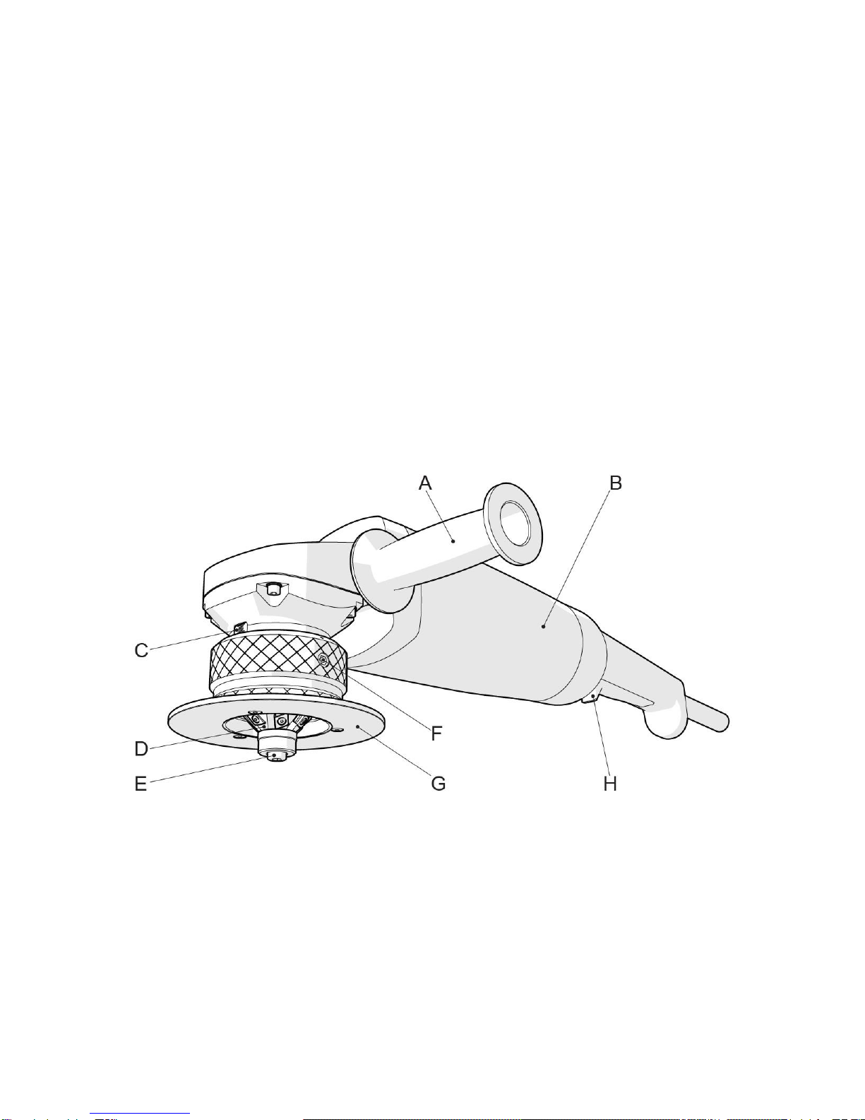
10. Control elements B15 AIR
Fig.10.0.1
A. Handle
B. Motor body
C. Scale for reading the bevel size setting
D. The miller unit with indexable inserts
E. Guiding, stop miller roller and roller screw
F. The arresting screws of the thrust place sleeve –The set removal provision
G. The thrust plate with sleeve
H. Main switch

9
11. Use
Important:
The device can be used solely if it is fitted with the original indexable inserts supplied by
our supplier, i.e. the device manufacturer. It includes four-sided indexable inserts. The
device can be fitted with 6 pieces of indexable inserts. It is prohibited to use other than
original inserts.
11.1 Setting the removal size
Attention :
During the adjustment operation, wear gloves and other personal protective
equipment. The operations must be carried out on the machine at rest and after
disconnecting from the power supply.
Disconnect the machine from electricity supply.
Release the setting arresting screws (fig.10.0.1 position F)
Turn the guiding plate (fig.10.0.1 position G) for setting the reduction size. You can
read the setting on the scale (fig.10.0.1 position C). Stupnice je pouze orientační a
výsledný úběr může být jiný při použití různých úhlů frézovacích hlav.
After setting, fasten both screws (fig.10.0.1 position F).
Important:
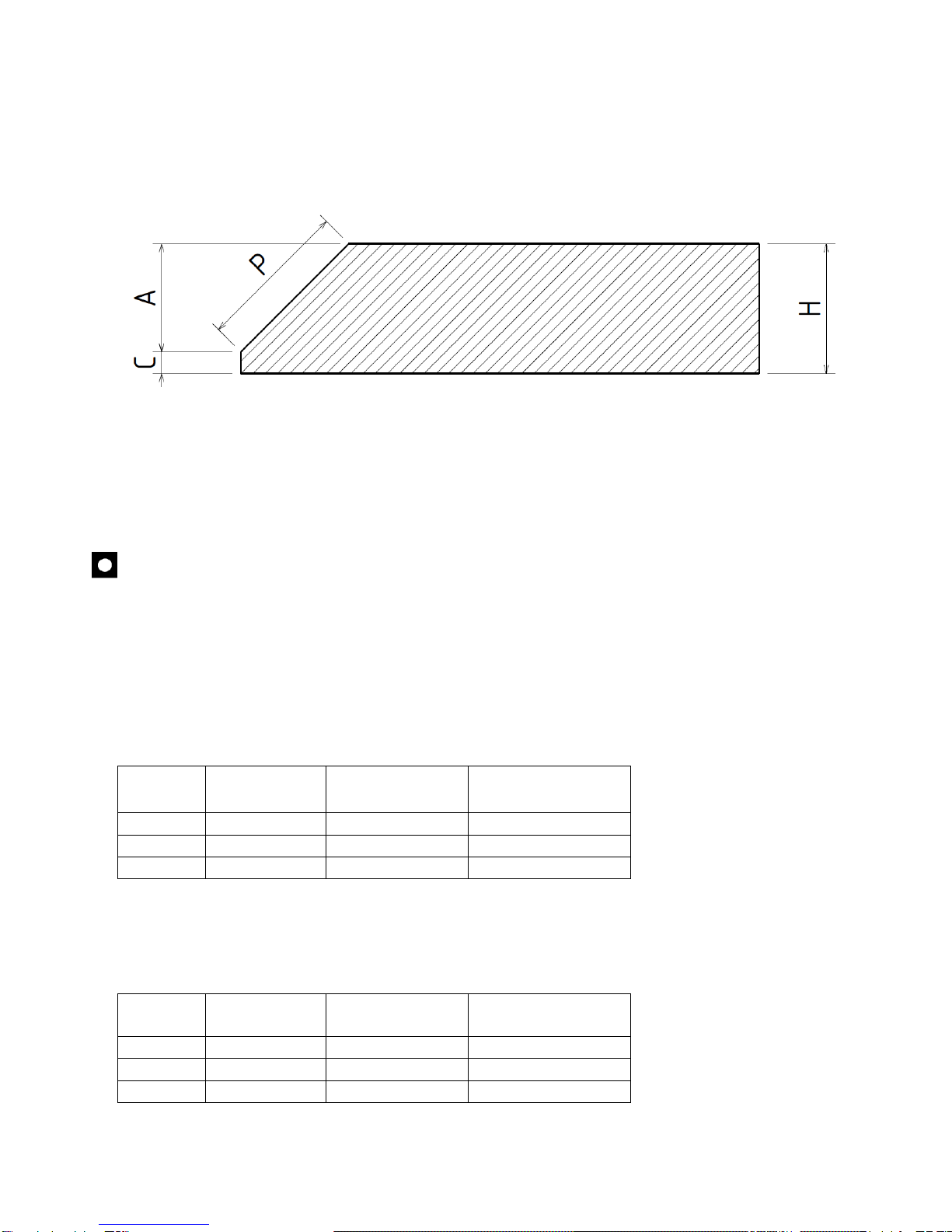
Maximum reduction is 15mm of bevel width (dimension P fig.11.1.1). The reduction can be
achieved in more steps. It depends on the material solidity. We recommend performing the
test.
Start with lower reduction and gradually increase the value until the work with the machine is
comfortable and the plates can achieve gradually reduction without increased vibrations. For
orientation setting, use the tables below.
We recommend administering the work log for recording the measured value and the
machining procedure.
10
Fig. 11.1.1
For orientation setting of the reduction size and the independent machining process, use
the setting tables for individual bevel angles.
Important:
The values in the table are calculated from point 0. Point is the point when the
miller touches the material edge for the first time. This point can be set by
gradual turning of the thrust plate (fig.10.0.1 position G) and placing to the
material edge.
45° - For full bevel (P=15mm) is required, turn the thrust plate by 5,2 revolutions
Chip no.
Hypotenuse P
Bevel height A
Number of rpm
of the thrust
plate
I.
5mm
3.5mm
2 Revolutions
II.
11mm
7.8mm
+ 2 Revolutions
III.
15mm
10.6mm
+ 1.2
Revolutions
See fig.11.1.1.
30° - For full bevel (P=15mm) is required, turn the thrust plate by 6.2 revolutions
Chip no.
Hypotenuse P
Bevel height A
Number of rpm
of the thrust
plate
I.
5mm
4.3mm
2 Revolutions
II.
10mm
8.6mm
+ 2 Revolutions
III.
15mm
13mm
+ 2.2
Revolutions
See fig.11.1.1.

11
Important:
The machine was constructed for the preparation of welded surfaces. Machining
accuracy is within limit
+/-1mm. The condition for reaching the satisfactory results is a perfect
preparation of the material edges. Unfortunately the material is often burned or
cut. The inaccuracy shall be reflected on the resulting machining.
Important:
If it is difficult to machine the bevel within the recommended number of steps,
we recommend dividing the process to more chips. The reason can be the wear of
the cutting inserts or worse machining properties of material.
11.2 Bevelling
Connect the device in electricity distribution
After careful setting of the first reduction, see clause 11.1, hold the device with
both hands and use the main switch to switch on the device.
Fit the machine on material in such way the thrust/contact plate (fig. 10.0.1 position
G) was in contact with material at maximum possible surface.
Slowly move the machine to the material until you feel the milling machine is in
reduction. CAUTION!!! The rebound is possible at this moment, be careful.
Press the machine in the direction into the material until the miller is embedded in
the material in the full profile of the set chip. Contact roller (fig. 10.0.1 position E)
must now touch the workpiece edge. The thrust plate (fig. 10.0.1 position G) must be
placed with the surface on material.
Now, you can start the machining from the left to the right. Shift the machine
constantly; using only such speed the milling machine was able to remove material
in the set chip profile. Otherwise, the milling machine will be pushed out from the
material and the bevel will be unequal.
Attention :
During work, wear gloves and other personal protective equipment.
The maintenance operations must be carried out on the machine at rest and after
disconnecting from the power supply.
Important:
The shift during machining is always from left to the right.

12
Attention :
The device operators must hold the device with both hands.
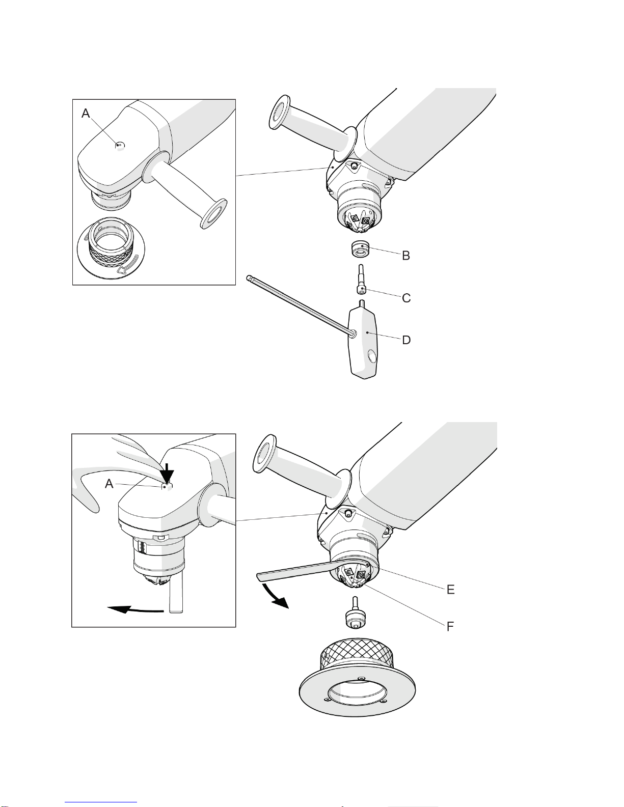
11.3 Bevel angle and shape change. Milling head replacement
Machine B15 ELECTRA is constructed for the use of more milling heads, see chapter
8. Accessories.
For the head replacement, proceed as follows.
Disconnect the machine from electricity supply.
Release the setting arresting screws (fig.11.3.1 position A) by the enclosed allen key
(fig. 11.3.1 position C)
Turn the guiding plate (fig.11.3.1 position B) for complete disassembly from the
machine
Secure the spindle against turning with the button, which is located on the top side of
the gearbox (fig 11.3.2 position A)
Use the allen key (fig.11.3.2 position D), release and disassemble the roller screw
(fig. 11.3.2 position C) and roller (fig.11.3.2 position B)
Now disassemble the milling head (fig.11.3.3 position F) by enclosed hook spanner
(fig.11.3.3 position E)
Use the same process to assemble new head and reassemble the machine.
All connections must be appropriately fastened.
Fig. 11.3.1
13
Fig. 11.3.2
Fig. 11.3.3

14
Attention :
During the adjustment operation, wear gloves and other personal protective
equipment. The operations must be carried out on the machine at rest and
after disconnecting from the power supply.
11.4 Replacement of indexable
inserts
Important:
Work solely with sharp and not damaged indexable inserts. It prevents the
machine damage. If the cutting inserts are worn or damaged or cracked,
they must be replaced.
Attach the wrench (fig. 11.3.1 position D) release the screws used for fastening
the indexable inserts (fig. 11.3.1 position C)
Indexable inserts (fig. 11.3.1 position B) replace with new, different, or just turn
them to use all cutting edges.. Attention! Considering the specific shape, focus on
this operation.
Indexable inserts must be appropriately fastened (fig. 11.3.1 position C).
Assemble the guiding plate set according to chapter 11.3
Fig. 11.4.1

15
12. Maintenance and operation
Maintenance of machine B15 ELECTRA does not require any special tools and it is
very simple. Keep the machine clean and replace the lubrication grease in the
machine gearbox every 1000 working hours. This operation must be performed solely
in authorised service N.KO Machines.
Regularly check the supply power cable. In case of damage have it replaced in an
authorised service shop authorised to perform the such repairs. Contact your supplier.
Important:
The moving parts, threads, and mechanical connections must be gradually
cleaned using compressed, and must be preserved (greased).
Attention :
When using compressed air for cleaning, wear safety goggles and never use a
pressure exceeding 2 bar.
13. Spare parts
Orders of spare parts shall contain the following information:
machine type;
serial number;
Description of required part and its number
quantity.

16
13.1 List of spare parts

17

18

19
A copy of this manual is supplied with every
machine B15
ELECTRA
All rights reserved.
No part of this publication may be reproduced without the previous consent granted by the company
N.KO.
Manufacturer's and Distributor's Address:
N.KO spol. s r.o.
a Member of Richtr Group
Táborská 398/22
293 01 Mladá Boleslav
Czech Republic –Europe Union
Phone: +420 326 772 001 fax: +420 326 774 279
email:nko@nko.cz
USA Distributor's Address:
BEVELER USA INC.
a Member of Richtr Group
Business Office, Workshop, Warehouse
328 14th Street
Ambridge, PA 15003
Toll Free Number: 1-800-973-1138
Phone Ambridge (PA) office: 1-412-452-2563
email:service@bevelerusa.com
Table of contents
Popular Power Tools manuals by other brands

Teccpo
Teccpo TAHG01P user manual

Parkside
Parkside PKGA 40-Li A1 Translation of the original instructions

Gearwrench
Gearwrench 88721 Instruction Manual & Product Warnings

Josef Kihlberg
Josef Kihlberg JK1219HT operating instructions

Bomag
Bomag BPR 45/55 D operating instructions

Hitachi
Hitachi CJ 18DSL Handling instructions


