Sefa DUPLEX PRO User manual

English version translated from original french version
V0919
INSTRUCTION MANUAL
DUPLEX PRO
DUPLEX AIR PRO
DUPLEX LITE
S.E.F.A®
Z.I PASTABRAC
11260 ESPERAZA
FRANCE
Tel : 33 (0)4.68.74.05.89 -Fax : 33. (0)4.68.74.24.08
E-Mail : contact@sefa.fr
English Version
V0919
Page 1
WARRANTY CONDITIONS
The warranty period begins from the day the equipment is commissioning at the user's premises, as
evidenced by the return of the guarantee form and the delivery note, for a period of two years for a
current use of 8 hours a day, ie 3000 hours.
The warranty is strictly limited to our materials, against defects in material and workmanship.
It is up to the buyer to prove the said defects.
Our liability is limited to the obligation to rectify or replace parts, free of charge, recognized defective
by us, without being able to claim any compensation for any reason whatsoever.
Replaced parts under warranty:
Remain our property,
Deposit billed
A cancellation credit is triggered upon the return of defective parts.
The return will have to occur ONE MONTH MAXIMUM after the intervention.
THE WARRANTY DOES NOT COVER :
Consumable supplies such as:
- Fuses, LED, gasket, hoses, nozzles, filters ...
- The supplies not being our pure manufacture, are under the guarantee of their manufacturer.
WARRANTY DOES NOT APPLY :
Replacements or repairs that would result from normal wear and tear of the equipment and
machinery, damage or accidents due to negligence, lack of supervision or maintenance, defective use
or modifications without our written consent.
In the event of a defect originating from the material supplied by the purchaser, nor of a design
imposed by this one.
To repairs that would result from damage or accidents occurring during transport.
To the maintenance operations and adjustments inherent to the use of the machine, and indicated in
the maintenance manual, such as:
- intermediary settings
- tightening of piping, etc. ...
For pneumatic machines, all traces of detergent oil in the pneumatic
circuit inhibit the guarantee conditions mentioned above.
For technical information or ordering spare parts,
give the machine reference and its serial number.

English Version
V0919
Page 2
INDEX
WARRANTY CONDITIONS .....................................................................................................................................................1
INDEX ..........................................................................................................................................................................................2
CHARACTERISTICS.................................................................................................................................................................3
GENERALITIES .........................................................................................................................................................................4
USE................................................................................................................................................................................................4
1. SECURITY.............................................................................................................................................................................5
a) International symbols.........................................................................................................................................................5
b) Important points.................................................................................................................................................................5
c) Safety features on the machine...........................................................................................................................................5
d) Emergency stop..................................................................................................................................................................5
e) Security guard....................................................................................................................................................................5
f) Verification of the operation of the safety device................................................................................................................6
g) After an emergency stop.....................................................................................................................................................6
h) Manual...............................................................................................................................................................................6
2. INSTALLATION OF THE MACHINE..............................................................................................................................6
3. START-UP............................................................................................................................................................................8
4. CONTROL PANEL ..........................................................................................................................................................10
5. SETTINGS ..........................................................................................................................................................................11
a) Temperature.....................................................................................................................................................................11
b) Timers ..............................................................................................................................................................................11
c) Counters and Modes.........................................................................................................................................................11
c) Rotation Speed .................................................................................................................................................................11
6. DESCRIPTION OF THE OPERATING CYCLE...........................................................................................................12
a) For Duplex LITE ..........................................................................................................................................................12
b) For Duplex PRO...........................................................................................................................................................12
c) For Duplex AIR PRO ...................................................................................................................................................12
7. PARAMETERS..................................................................................................................................................................13
a) Status bar.........................................................................................................................................................................13
b) Digital keypad..................................................................................................................................................................14
c) Recipes .............................................................................................................................................................................14
d) Setting menu and diagnosis..............................................................................................................................................15
e) Ergonomics settings .........................................................................................................................................................16
f) Energy Mode.....................................................................................................................................................................16
g) Time / Language ..............................................................................................................................................................18
h) Information ......................................................................................................................................................................18
i) Factory settings.................................................................................................................................................................19
8. DIAGNOSIS ......................................................................................................................................................................19
a) Alarms and warnings .......................................................................................................................................................20
b) Summary Alarms-Events..................................................................................................................................................21
9. OPERATING CYCLE .......................................................................................................................................................22
a) Operating mode ...............................................................................................................................................................22
b) Number of timers..............................................................................................................................................................23
..................................................................................................................................................................................................23
IMPLANTATION OF EQUIPMENT......................................................................................................................................24
DUPLEX PRO ELECTRICAL DIAGRAM............................................................................................................................28
DUPLEX PRO PNEUMATIC DIAGRAM..............................................................................................................................29
DUPLEX LITE ELECTRICAL DIAGRAM...........................................................................................................................30
DUPLEX LITE PNEUMATIC DIAGRAM.............................................................................................................................31
MAINTENANCE .......................................................................................................................................................................34
1. REPLACEMENT OF WASTE PARTS ...........................................................................................................................34
a) Silicone foam mat.............................................................................................................................................................34
b) Other parts.......................................................................................................................................................................34
2. MAINTENANCE...............................................................................................................................................................34

English Version
V0919
Page 3
PIECES SUBJECT TO WEAR ................................................................................................................................................35
QUICK RESPONSE TIPS ........................................................................................................................................................36
SERVICE BOOK.......................................................................................................................................................................37
CHARACTERISTICS
Document non contractuel : en fonction des progrès techniques, nous nous réservons le droit de modifier les caractéristiques de nos produits.
Characteristics
Weight in working order
193 kg
Height
751 mm
Depth
1005 mm
Width
1071 mm
Dimensions of the plate
400 x 500 mm
Power supply
220/240 V Single phase + Ground 50/60 Hz
Power
3200 W
Amperage
14A
Electronic temperature controller
Accurate to
+/- 1% of max temperature.
Adjustable from
0 to 220 °C
Electronic timer
Accurate to
+/- 1%
Adjustable from
0s to 59min 59sec
Terms of use
Noise
Less than 70 dB (A)
Ambient temperature of use
From 10°C to 35°C
Hygrometry
Less than 90%
Max pressing force
925 daN
English Version
V0919
Page 4
GENERALITIES
This hot-pressing machine has been designed to perform intensive production while respecting the
article L 233-5 of the Labor Code, to ensure the safety of the user.
This press has been designed for an operator working in front of the machine.
USE
It is recommended to read the "instructions for use" carefully before starting any pressing operation.
The press must be used by an authorized person who has been informed of the risks that may be
caused by misuse of the equipment.
The adjustments (pneumatic, electrical and mechanical) made by our technicians in the workshop as
well as the safety devices installed on the machine must not be modified under any circumstances.
Otherwise, the company SEFA will release all responsibilities on possible problems related to the said
machine.
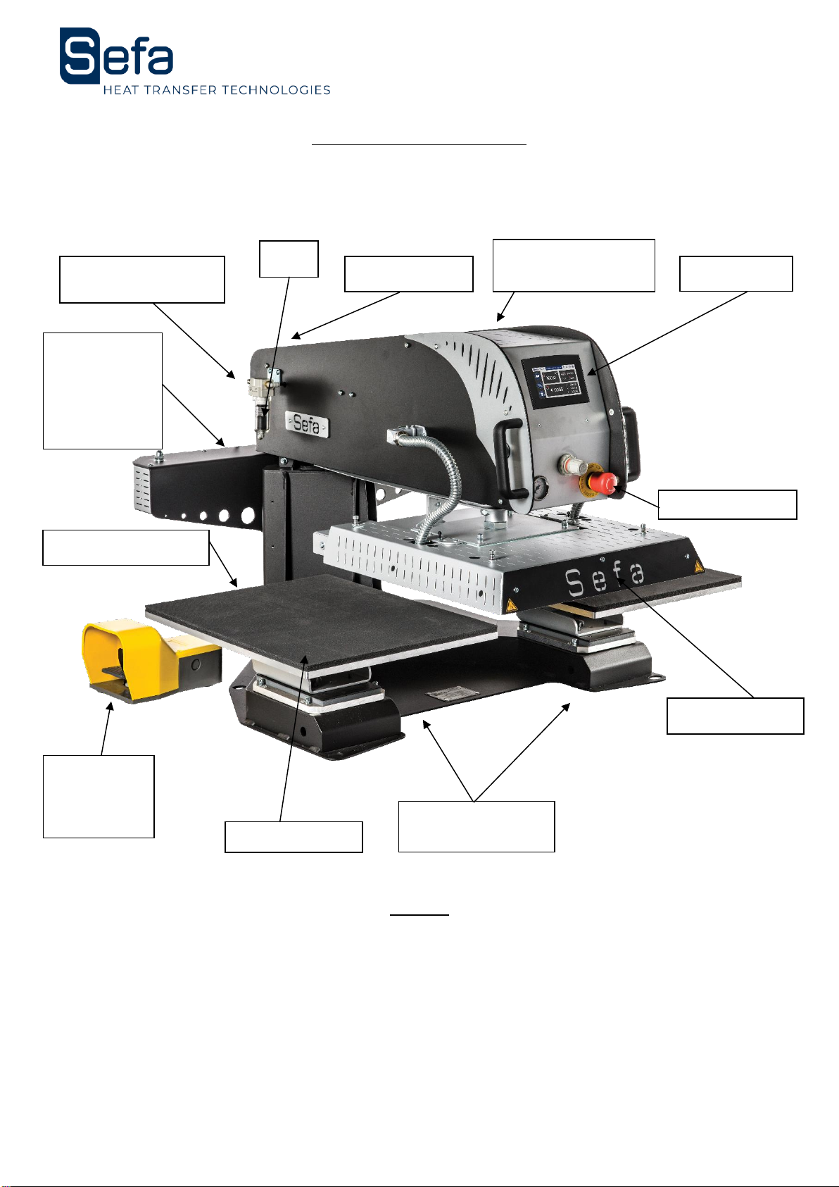
Heating plate
Emergency stop
Silicone foam
Removable lower
plates
Filter
Touchscreen
Hood + Relay
+ Fuses
Power supply
Pneumatic supply
connection
Automatic
rotation
cylinder
(not available
on Duplex
lite)
Transport bars
Foot Pedal
(not
available on
Duplex lite)

English Version
V0919
Page 5
1. SECURITY
THIS DEVICE IS DESIGNED TO BE USED BY ONE USER
USE BY QUALIFIED PERSONNEL
a) International symbols
b) Important points
Obtain personal protective equipment E.P.I. (gloves and glasses for example)
Do not touch the hot parts of the device during use.
Do not put hands between the trays once the device is turned on.
When handling, ensure that the operator does not risk anything in terms of burns, electrocution or
other.
Perform a daily inspection of the machine before starting production.
In the area around the machine, make sure there is no one before starting.
If the machine does not work properly, switch off the power supply immediately and look for the
cause (see chapter "Maintenance" in the manual).
c) Safety features on the machine
Protections and safety devices must not be modified.
They must be reassembled in case of possible removal for maintenance.
They must be kept in place and in good condition during normal operation.
The DUPLEX PRO is equipped with safety systems that protect the operator from pinching.
The main security features are:
d) Emergency stop
Located on the front of the machine: if the operator activates it, it turns off the machine.
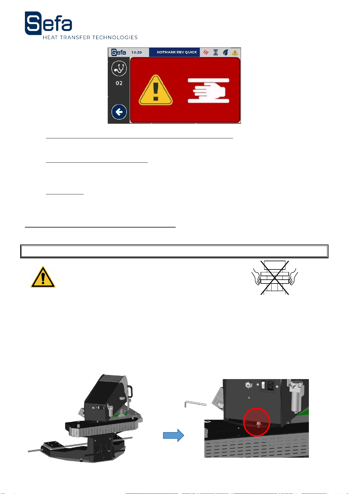
e) Security guard
Above the upper heating plate are two tab switches.
This system prevents the risk of pinching and crushing the operator.
If the system detects an obstacle, the heating plate rises, the rotation is deactivated immediately and
the press goes into safety mode.
You must press the red zone on the "Alarm" page, position the stem above one of the lower plates
and press the pedal so that the machine is functional again.
OFF
ON
DANGER, WARNING
HOT SURFACE
RISK OF ELECTROCUTION
English Version
V0919
Page 6
f) Verification of the operation of the safety device
Try the emergency stop and the safety cover daily.
g) After an emergency stop
In order to restart the nominal operation, check if there are any other problems on the machine.
Unlock the emergency stop by turning the red part: the machine will reset automatically.
h) Manual
It is provided during the delivery of the machine, technical documentation on the components used.
Please read it before handling the SEFA machine.
2. INSTALLATION OF THE MACHINE
USE BY QUALIFIED PERSONNEL
Do not handle the machine by the trays!
Cut the straps from the crate and unscrew the screws holding the cover and the bell. Remove the lid
and the bell from the box.
Remove the plastic bag protecting the machine.
Remove the lag screws that secure the machine to its pallet.
After removing the packaging, remove the security screw using the Allen key 4 provided.
English Version
V0919
Page 7
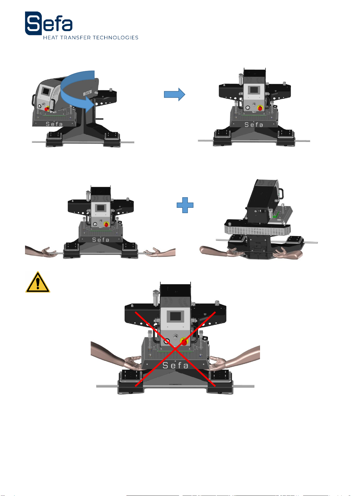
Center the machine between the two plates.
Position the transport bars and handle the machine only by them.
Warning ! Do not lift the machine by the trays.
Fix the machine on a stable and level table by manipulating it with the transport bars.
Position and secure the bottom plates if it is not done.
Remove and store the transport bars with the machine box in case of future transport of the
machine.

English Version
V0919
Page 8
3. START-UP
Supply compressed air to the machine. The compressor must provide at least 4 bars.
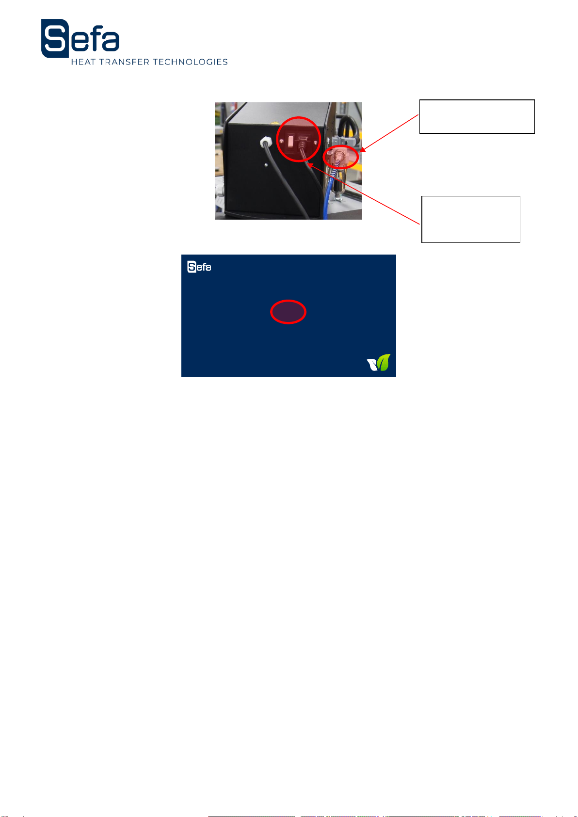
Power the machine with the supplied power cord.
Position the button on the back of the stem to "1" and check that the emergency stop button
on the front of the stem is unlocked. Clipper the cable as described below:
Place the power cable facing
the notch
Push the cable until you hear a
"clic"
Your cable is now fixed
English Version
V0919
Page 9
Turn on the machine by flipping the main switch on the back of the machine.
The touch screen will display the following start page:
Tap the screen to access the following pages.
This machine must be used by qualified personnel. When powering up, the temperature control, PLC
and power supplies are energized.
Pneumatic network
connection
Electrical
connection
230VAC-20A
English Version
V0919
Page 10
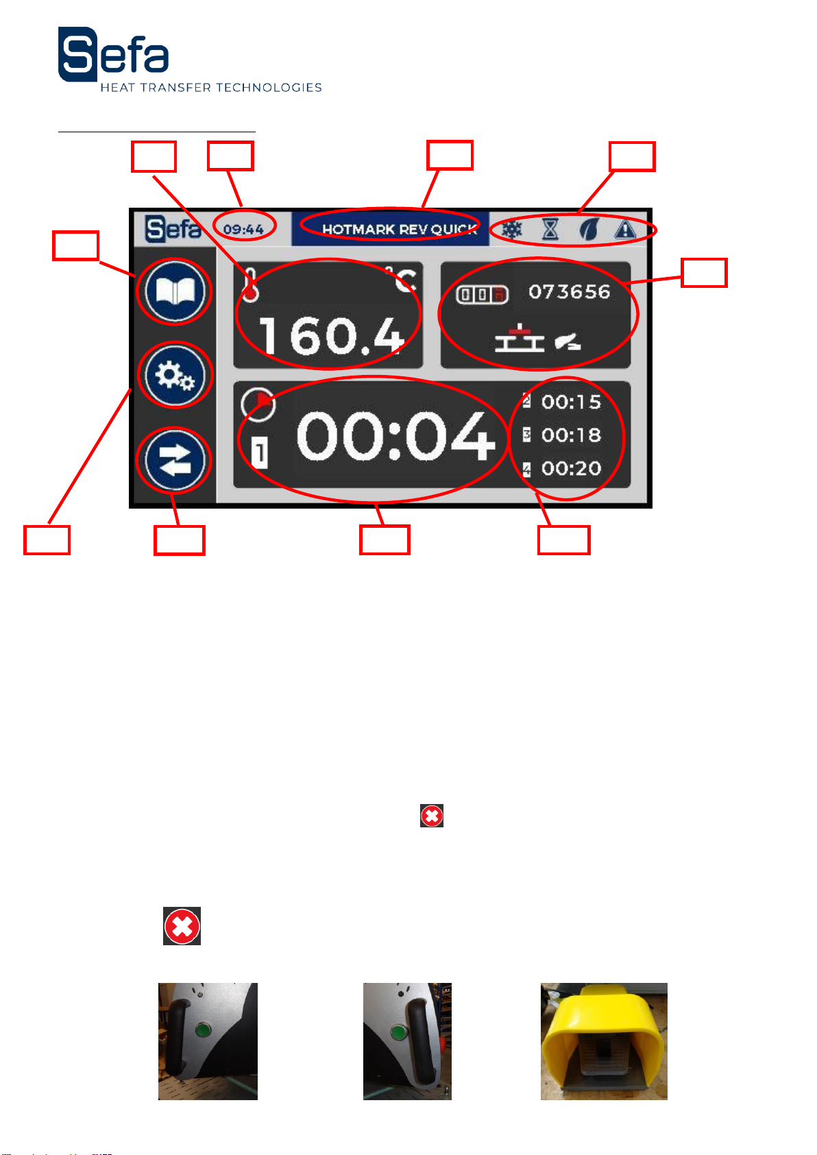
4. CONTROL PANEL
1) Measured temperature and temperature setting
(0 to 220 ° C): The numbers are
a. Red when the temperature is above the set value
b. Blue when the temperature is below the set value
c. White when the temperature is at the set value
2) Time
3) Name of active recipe
4) Status bar (Heat –Cycle –ECO mode –Warning)
5) Daily counter / Working mode
6) Active timer
7) Next timers (4 possible timers)
8) Recipe button
9) Settings button
10) Exchange plate button –STOP during cycle
The green start buttons and foot pedal allow the start of the pressing cycle. This action is only possible
on this page.
For shutdown two modes exist:
1) STOP button : The heating plate goes up and the press stop moving.
2) Press the Foot Pedal or green button: the plate goes up, moves to the opposite position and stops.
1)
2)
3)
4)
5)
7)
6)
10)
9)
8)
English Version
V0919
Page 11
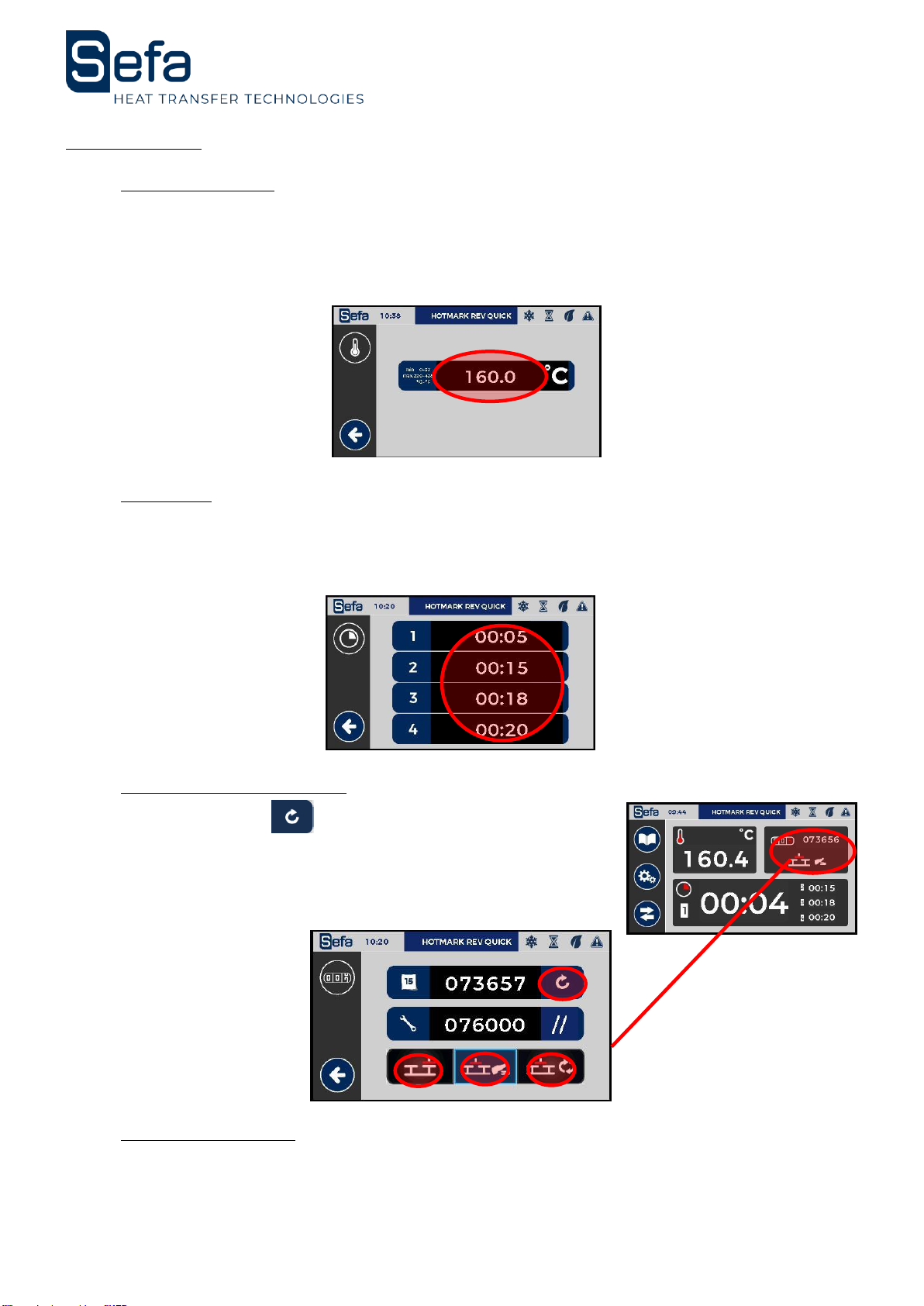
5. SETTINGS
a) Temperature
Touch the area of the screen where the temperature is indicated.
Press the temperature setting.
A numeric keypad appears to enter the new value.
This value is immediately entered in the current recipe.
Press the arrow at the bottom right to return to the work screen.
b) Timers
Touch the area of the screen where the timers are indicated.
Then enter using the numeric keypad each value of the timers.
Press the arrow at the bottom right to return to the work screen.
These values are immediately entered in the current recipe.
c) Counters and Modes
Press 3 seconds on to reset the daily counter
A totalizer is located below.
To change the operating mode press the following button:
Mode single plate
Mode Semi-Auto (pedal)
Mode Auto
c) Rotation Speed
Contact your official SEFA distributor to adjust this setting.

English Version
V0919
Page 12
6. DESCRIPTION OF THE OPERATING CYCLE
a) For Duplex LITE
1. Place the item on the lower tray.
2. Adjust the transfer sheet.
3. Move the swing arm away the platen you want to work.
4. Push and maintain during 3 seconds the 2 bimanual buttons
5. Heat platen will lower and the press timer will start
6. Use this time to prepare the next work item and transfer sheet on the second
workstation.
7. The heat platen will lift open when the timer has finished
8. Remove the work item from the first workstation and get the next one ready.
9. Repeat from step three above.
10. Pressing the stop button during a cycle will stop the cycle.
b) For Duplex PRO
Place the hating plate on the opposite side to where you want to work.
Test by pressing the pedal or the green push button to validate your choice.
1. Place the item on the lower tray.
2. Adjust the transfer sheet.
3. Press the start pedal cycle. The stem automatically moves to the tray, the warming
plate automatically descends and activates the press timer.
4. Meanwhile, prepare the item and its transfer sheet on the second station.
5. At the end of the countdown of the timer, the heating plate will go up again.
6. If the machine is not in "FULL AUTO" mode, press the pedal. Otherwise the rotation
will be done automatically after raising and counting the "timer after pressing" (see 5.c
Counters and Modes)
7. Remove the item from the first item and prepare the next item.
8. Repeat the operation at the third point.
During the cycle, pressing the pedal or one of the green pushbuttons stops the cycle and releases the
stem from the opposite side.
During the cycle, pressing the stop button on the screen stops the pressing cycle.
c) For Duplex AIR PRO
Place the hating plate on the opposite side to where you want to work.
Test by pressing the pedal or the green push button to validate your choice.
1. Place the item on the lower tray.
2. Adjust the transfer sheet.
3. Press the start pedal cycle. The stem automatically moves to the tray, membrane
swells then the warming plate automatically descends and activates the press timer.
4. Meanwhile, prepare the item and its transfer sheet on the second station.
5. At the end of the countdown of the timer, membrane deflates and the heating plate
will go up again.
6. If the machine is not in "FULL AUTO" mode, press the pedal. Otherwise the rotation
will be done automatically after raising and counting the "timer after pressing" (see 5.c
Counters and Modes)
7. Remove the item from the first item and prepare the next item.
8. Repeat the operation at the third point.
English Version
V0919
Page 13
During the cycle, pressing the pedal or one of the green pushbuttons stops the cycle and releases the
stem from the opposite side.
During the cycle, pressing the stop button on the screen stops the pressing cycle.
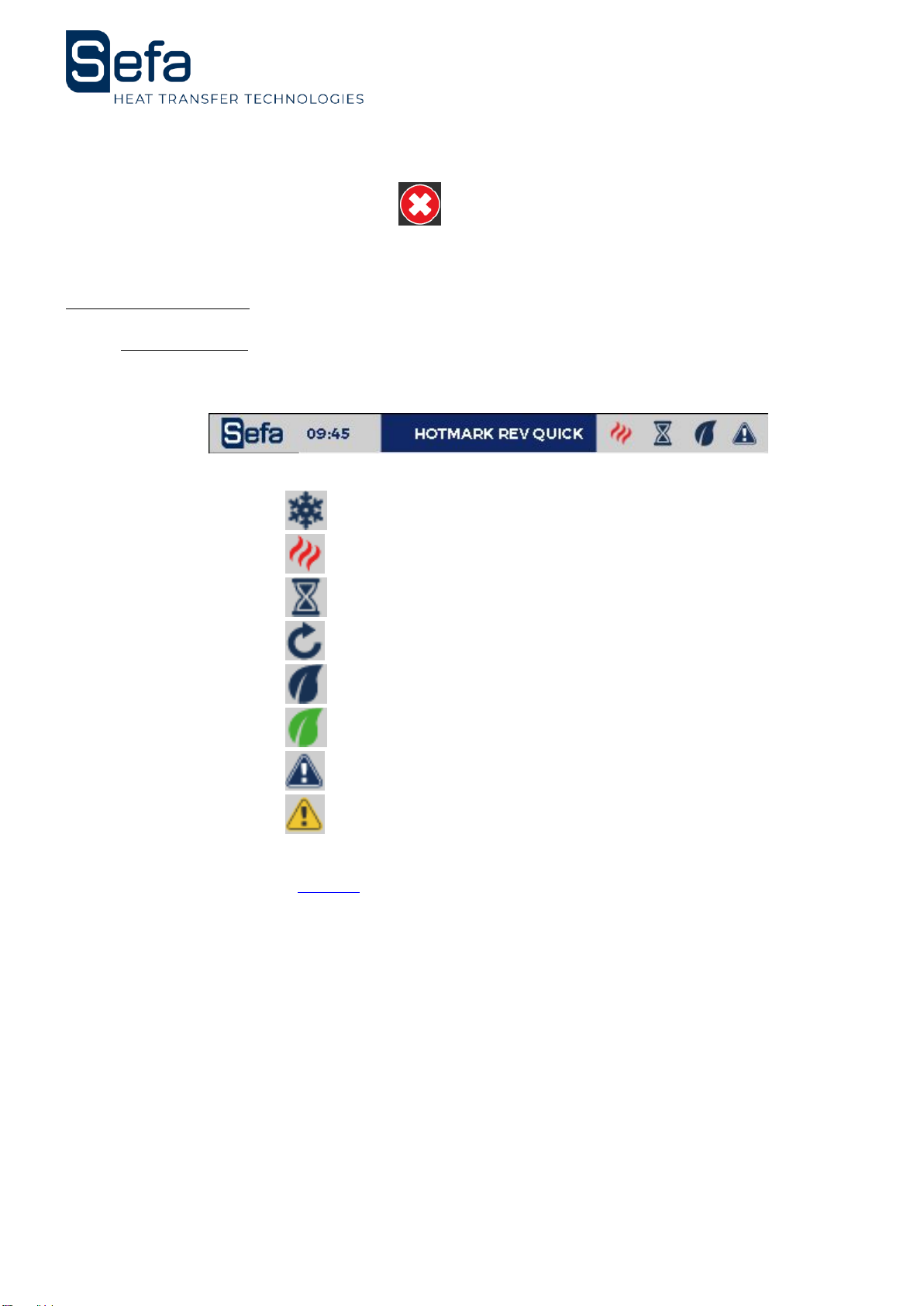
7. PARAMETERS
a) Status bar
The status bar allows you to know the status of the machine on any activated page.
Logo Time Active Recipe Heat status –Cycle –Eco –Warning
Heating status : Blue flake = Stop
Red flame = On. Blinks between the two states in regulation.
Cycle : Machine ready to work.
Cycle in progress (Rotating arrow).
Eco mode : Eco mode OFF
Eco mode ON
Warnings : No warning
Warning activated
No action is possible. It’s just an information.
Time is defined in the section page 17.
English Version
V0919
Page 14
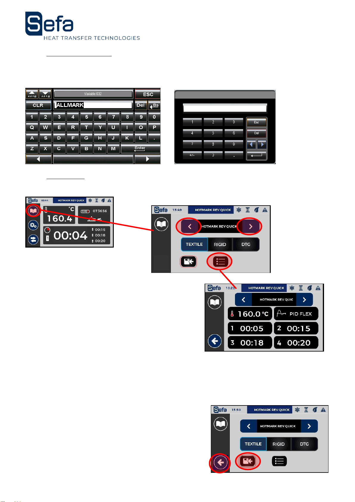
b) Digital keypad
The numeric keypad allows you to enter values such as temperature or times. An alphanumeric
keyboard allows you to enter the name you want to give to the recipe.
c) Recipes
The system is designed to receive up to 6 different recipes. Each recipe can be renamed with 16
characters. You can access the appointment page for recipes and choice of regulation as follows:
The recipe store :
The name
The type of regulation
4 different timers
These values are summarized in the following page:
The following regulations are available for each type of product:
- Flex and flock, screen-printing transfers, laser transfers, flex in less than 5 seconds, pressing of
digital printed textiles, sublimation textiles = TEXTILE
- Drying of pretreatment on textiles = DTG
- Sublimation of rigid materials = RIGID
To leave the page, you must first save the recipe even if
there has been no change.
The exit button at the bottom left of the screen, appears
to leave the page.

English Version
V0919
Page 15
d) Setting menu and diagnosis
Push the button on the left of the screen to access the settings.
Click on the desired menu to access it.
Press the arrow on the bottom right to get out.
ECO Modes (2 pages)
Firmware information
Protected access
Diagnosis (I/O,
warnings)
Time
Settings (Buzzer,
timers, etc.)

English Version
V0919
Page 16
e) Ergonomics settings
(1) Buzzer ON/OFF = Disables or activates the buzzer when touching the screen and at the end of
the cycle. The buzzer remains operational in the event of a fault (5 rings).
(2) Buzzer « End of cycle » ON/OFF = ring 2 seconds before the end of the cycle.
(3) Access to the page "Rotation - temperature range"
(4) Unit change : allows to change temperature unit (° Celsius or ° Fahrenheit)
(5) Choice of number of timer: 3 positions single timer, 2 timers or 4 different timers and
configurable.
(6) Switching delay: In auto mode, wait for rotation of the stem before the next cycle (in seconds
and tenth of a second).
(7) Operating temperature range of the machine: allows the start of the cycle to be conditioned
when the temperature has not yet been reached or exceeded.
a. Minimum : from -30 to 0°C or from -86 to 0°F.
b. Maximum : from 0 to 30°C or from 0 to 86°F.
(8) Back to Menu
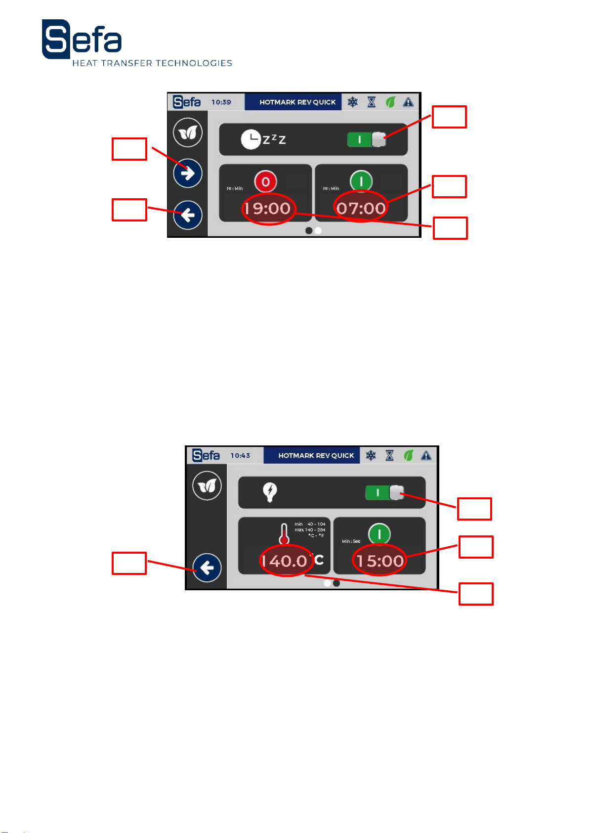
f) Energy Mode
The energy mode has two settings: a long standby setting and a short standby setting.
The long standby mode puts the machine into hibernation for the time defined by the two
parameters. The temperature is then turned off, it will drop to room temperature. (No energy
consumption). If the machine is in automatic mode, it stops at the set time. The program displays the
idle page to indicate that it is paused. The brightness decreases and oscillates slightly. This mode also
allows an early start of the heating, for example before taking post. For this, it is necessary to leave the
machine under tension.
(5)
(6)
(1)
(8)
(2)
(4)
(3)
(6)(7)
English Version
V0919
Page 17
(1) Extended standby mode ON / OFF.
(2) Setting the sleep time.
(3) Setting the heating time.
(4) Next page: short sleep.
(5) Short standby mode ON / OFF.
(9) Short standby temperature.
a. Minimum: 40 ° C or 104 ° F.
b. Maximum: 140 ° C or 284 ° F.
(6) Period after which the machine goes to standby when there has been no pressing of the
green push buttons or the pedal, no press on the screen or an active output (press cycle).
(7) Return to the previous screen.
Short standby will lower the temperature after a time of inactivation (no cycle, no touch on the
screen). The program displays the idle page to indicate that it is paused. The brightness decreases
and oscillates slightly.
Regarding the temperature, in eco mode, it is impossible to ask for a lower temperature than
the set point of the current recipe. In standby mode, it is impossible to ask for a temperature higher
than the temperature of the eco mode.
To exit the energy saving modes in progress, a touch on the screen is sufficient and
deactivates the mode (Button on "o").
(1)
(4)
(8)
(3)
(2)
(5)
(8)
(7)
(6)
English Version
V0919
Page 18
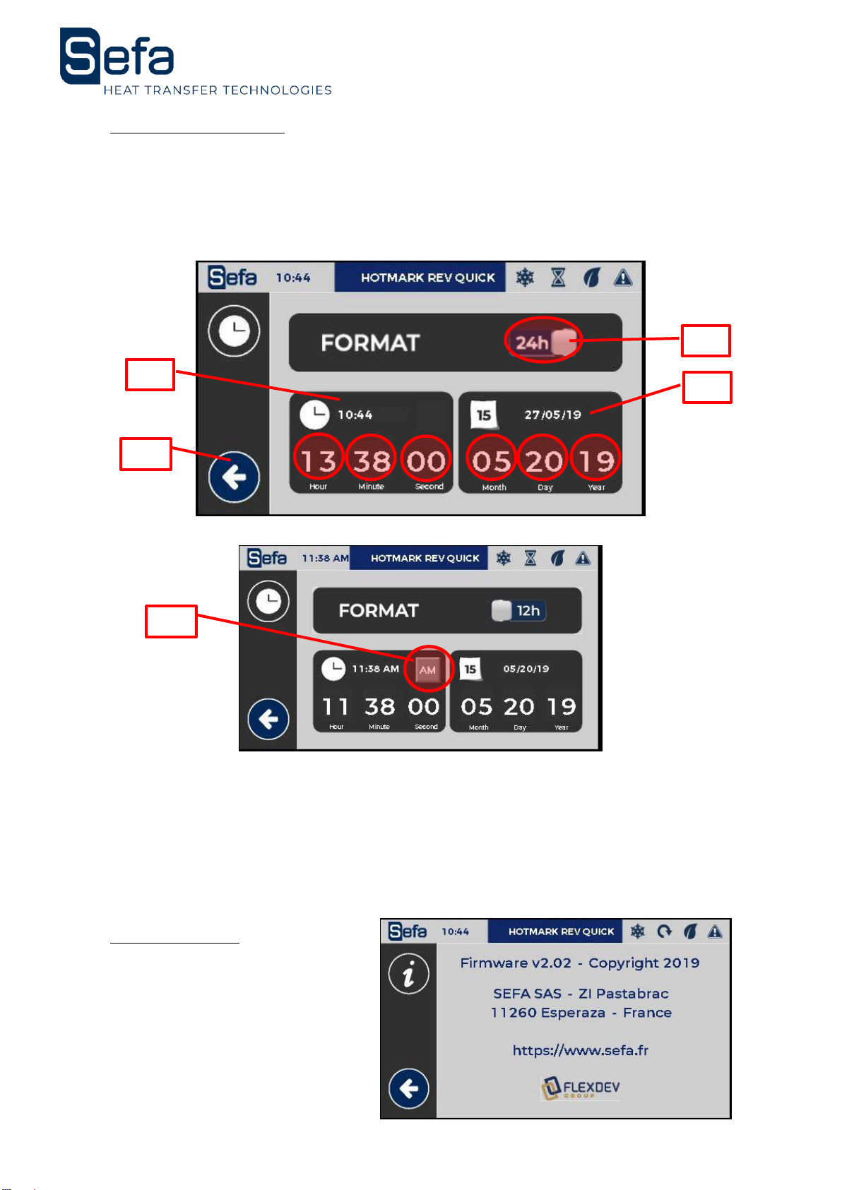
g) Time / Language
(1) Set the time format
(2) Set the time value
(3) Set the date value
(4) Set AM or PM
(5) Back to MENU
Procedure to set the date:
a. Choose format
b. Set time
c. Set date
d. Check values
e. Back
h) Information
Manufacturer –Firmware version.
(2)
(1)
(5)
(3)
(4)
English Version
V0919
Page 19
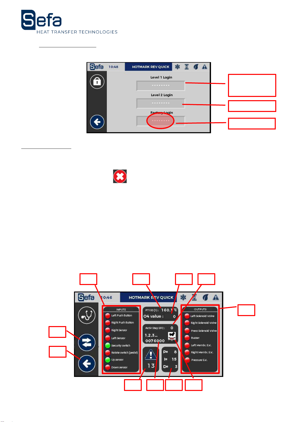
i) Factory settings
Change the factory settings, vital settings for the machine. Changing them voids the warranty.
Enter the password in the field dedicated :
8. DIAGNOSIS
To know the status of the inputs / outputs of the PLC.
On this page all operating cycles are possible by pressing the pedal and the green buttons.
Arrêt possible par l'appui du bouton
No action possible. This screen is used for troubleshooting and evaluating sensor and actuator states.
The support service can ask the operator to display it during a telephone intervention for example.
1) Inputs
2) Outputs
3) Temperature in ° Celsius or ° Fahrenheit
4) Analogue value of the static relay (resistance control) (0 to 1000 pts)
5) Active SFC Step: number of the active step during the cycle (0 to 10)
6) Totalizer counter (no reset)
7) Active mode: FULL AUTO, SEMI AUTO, 1 POST
8) Alarm in progress: access summary page alarms
9) PID control type (based on PID values)
10) Change plate and stop cycle button
11) Back to previous page
2)
10)
3)
4)
1)
9)
6)
Additionnal
pretected
access
Offset Setting
Factory setting
11)
5)
8)
7)
Other manuals for DUPLEX PRO
1
This manual suits for next models
1
Table of contents
Other Sefa Power Tools manuals

Sefa
Sefa INiTiUM User manual

Sefa
Sefa BR 180 PCAS User manual

Sefa
Sefa DUPLEX MINI PRO User manual

Sefa
Sefa DUPLEX V3 Series User manual

Sefa
Sefa CLAM SPORT V3 User manual

Sefa
Sefa LM V3 Series User manual

Sefa
Sefa LP 130 V3 User manual

Sefa
Sefa ROTEX V3 Series User manual

Sefa
Sefa ROTEX AIR V3 Series User manual

Sefa
Sefa DUPLEX PRO User manual


