Beyerdynamic QUINTA Series User manual

QUINTA
CONTROL PROTOCOL
FOR 3rd PARTY SYSTEM CONTROL
EDITION 3.0

2 Revision History
Table of contents
Revision History..................................................................................................................................................................3
1General Information.......................................................................................................................................... 4
2Connectivity and Information Commands..........................................................................................7
3System Configuration Commands..........................................................................................................17
4Conference Control Commands.............................................................................................................34
5(Advanced) MU List Management..........................................................................................................48
6Voting Commands............................................................................................................................................60
7Microphone Mode Commands................................................................................................................69
8Audio Setup Commands Digital Signal Processing................................................................ 80
9Use Cases...............................................................................................................................................................84

3 Revision History
Revision History
Version
Changes
Author
V1.0
Release of Document
GF
V2.0
Corrected baud rate, protocol changes for Quinta
update 09/2013
Added communication examples
Added new commands for Quinta CU Core Version
1.2.00 or higher
PE
V3.0
Complete document redesign
Added new commands to the already existing
chapters, plus many details and examples to the
command descriptions
Added Voting commands
Added List Operation commands
Added Microphone Mode commands
Added Audio Setup commands
Added Use Cases
ME, PE
4 General Information
1General Information
1.1 Interoperability
Communication with and control of the Quinta system requires a wired connection to
the control unit Quinta CU or respectively Quinta RS. Both devices offer three
communication ports: Ethernet, USB and
refers to Quinta CU or Quinta RS. Note: The AVB-Network connection does not allow
Quinta system control; it only offers AVB functionality (audio streams and AVB related
settings).
External controller: An external controller is a device, which communicates with the CU
and controls, manipulates Quinta settings (e.g. audio volume) or system status (e.g.
microphone on/off), or actively polls status information from the system. A PC with the
Quinta PC software is considered an external controller, likewise third-party systems
such as media control system (e.g. Crestron, AMX) and similar are considered external
controller.
It is important to understand that simultaneous control via Ethernet, USB
and
RS232 is
not supported. The CU allows at most one active external controller at a time,
regardless which port is used.
to the CU (hook up USB, RS232 and Ethernet) at the same time, only one external
controller may actively communicate with the CU at a time. Communication with the
CU requires the external controller to log in to the Quinta CU (refer to chapter 2.1: U
commands Login to communication port).
The CU features aninternal Quinta webserver. It can only be accessed via Ethernet, and
requires proper overall network environment. In order to access the webserver from a
browser, type in the CU IP-address into the browser URL-field. The webserver can be
used in parallel to an external controller. Note: The main intention of the web server is
system supervision and maintenance (e.g. check MU battery status, modify audio
volumes). Conference and microphone control (turning microphones on and off) is not
possible via webserver.
Listening on RS232: Microphone status messages are always sent via RS232 (even
without login), regardless of which other port is used by an external controller. Thus it is
possible to process this information in different ways, such as recording or using a
camera system which actively follows the active speaker. For this sake the camera
controller may be connected to the CU RS232-port, even while another external
controller communicates with the CU via Ethernet or USB.
The Quinta system offers two operation modes: Conference Mode and Microphone
Mode
important to know that some commands only work in Conference Mode, others only in
Microphone Mode. Please refer to the corresponding chapter.

5 General Information
1.2 Physical Interfaces
RS232 (Serial COM port): 57600 baud (8Bits, no Parity, 1 Stop). Requires 0-Modem
(crossover) cable, only TX, RX and GND pins are relevant.
USB: Will be recognized as virtual COM port (requires Quinta USB
driver), settings like above
TCP/IP (factory default): Telnet: Port 23
Default IP: 192.168.1.55
DHCP: active
1.3 General Operation Rules
Data format and communication concept
Please be sure to read this chapter carefully as it contains important information on
the serial communication used in the Quinta system.
Communication direction
Each command structure has a specific communication direction in which it is used in
the Quinta system. This direction is shown at the beginning of each table that breaks
down the commands in their structure. In order to provide a better overview in this
document, individual communication paths are assigned a specific color.
orange: Controller -> CU (wired communication)
blue: Controller -> CU -> MU (wired and wireless communication)
green: CU -> Controller (wired communication)
yellow: MU -> CU -> Controller (wired and wireless communication)
All communication uses ASCII characters
This means all received and sent information has to be coded using ASCII characters in
strings. Different parameters are separated by ASCII-blank characters (0x20).
Communication is built up in the following way:
(1) Commands use ASCII characters which are case sensitive. The single characters
are separated by ASCII-blank characters.
(2) Numeric values (e.g. volume-value) are also realized with ASCII characters which
in turn have to be interpreted as hexadecimal numbers, so that two ASCII-
characters represent a one-byte hexadecimal number.
The maximum number range depends on the command.
(3) In certain instances hexadecimal numbers following the command are
interpreted as a combined status information. In this case the hexadecimal
number has to be converted into the binary number representation. Individual
bits within this number represent certain status flags.
(4) Some information in the strings has to be interpreted as a usual string of ASCII-
characters which for example show a password.
Soyou alwayshavetotake acloserlook atthedocumentationofthecommands.
(5) Each command must end with an ASCII carriage return <CR>.

6 General Information
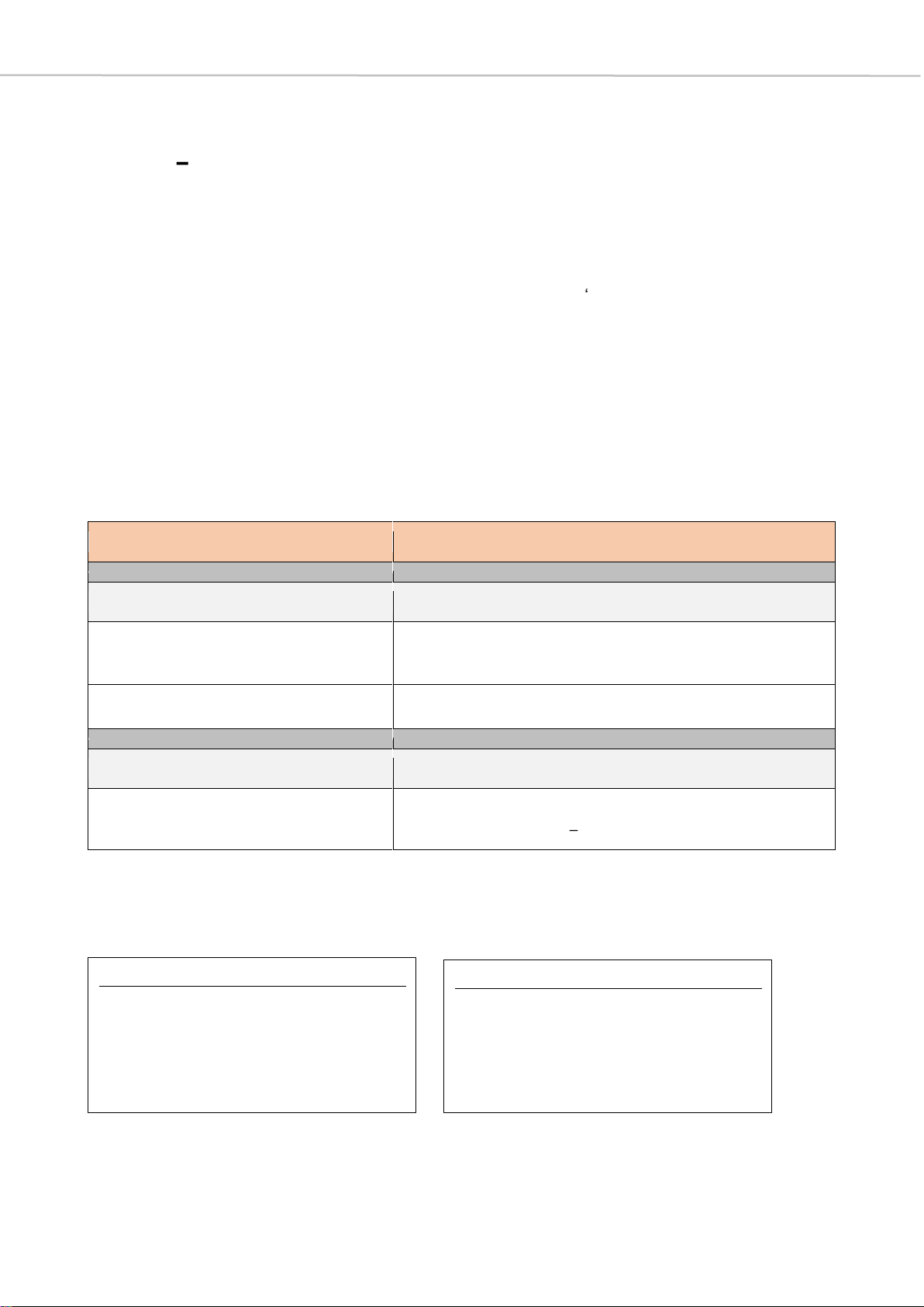
Examples
Command
characters
(important:
case
sensitive!)
Numeric value
OR
Combined status information in
particular bit positions
OR
Usual character string
ASCII <CR>
MU status
information
x
00021E 0131 7A 241100
<CR>
Login to
communication
port
U 0
pwd
<CR>
Acknowledge prompt
After receiving a valid command from controller, the CU will reply with the prompt >
(0x3E) to signal that it is ready for the next command. The controller shall not send
another command to the CU before receiving the >message from the previous
command. The only circumstance you are allowed to send a command without >
acknowledgement is due to timeout ( > not received after 5 seconds since last
command sent to CU).
Communication with the CU requires the external controller to log in to the Quinta CU
(refer to chapter 2.1: U commands Login to communication port).
1.4 Control Mode: Stand-alone or PC-controlled
The Quinta system offers two different control modes: stand-alone mode is used
without any software; an external controller can also send commands to control the
Quinta system in this mode. In PC-controlled mode, control of the Quinta system via
software is required; this can be Quinta software or third-party software.
With some command structures it makes a difference whether the system is used in
stand-alone mode or PC-controlled mode. For example, the a message, which follows
the q message of the MU, is only used in PC-controlled mode, since it is needed for
internal reasons in this case.
If there are concrete differences, these are explained in the description of the
commands in order to exclude possible incorrect use of the commands.

7 Connectivity and Information Commands
2Connectivity and Information Commands
All commands in this chapter are applicable in Conference Mode as well as
Microphone Mode.
2.1 Ucommands
Login to communication port
Note
The U commands are only sent by the controller to the CU and are not passed on to
other integrated units.
As already stated, in the further course of this document, the direction of
communication is presented in short form as in the first line of the following table.
Communication with the Quinta Control Unit via RS232, USB or Ethernet requires the
external controller to login first. Although the Quinta Control Unit offers three possible
physical ports namely: RS232, USB, Ethernet only oneport can beused at a time.Thus
only one external controller can communicate with the Quinta Control Unit at the same
time.
Communication direction
Controller -> CU
Syntax
Description
U 0
Unlock current communication port if no password is set
(factory default)
U 0 pwd
Unlock current communication port with password
U 1 pwd
Set password
Save it permanently in the CU
U 1
Clear password
U B
Lock all communication ports
Parameters
Description
pwd
password
(max. 15 ASCII characters, except: space, <CR>, <LF>)

8 Connectivity and Information Commands
Logging in with the U 0 command unlocks this very port to be used for communication.
Example: If the external controller sends the U 0 command to the CU RS232 port, it will
unlock the RS232 port for communication and control (the USB and Ethernet ports will
be locked for communication/control). Successive logins on another port, e.g. USB, will
unlockthe communicationfor theUSBport.Hence, itwilllock the formercommunication
port (in this example the RS232 port).
A new login is required after CU power up, CU reset, when changing to a different
communication port, or after all ports are locked by the U B command.
The access to the Quinta Control Unit can be password protected. The same password
is used throughout the Quinta System: PC-Software, CU access, web server access.
Thus, if the system is password protected, the login requires the correct system wide
password. Furthermore the password can be changed by protocol after login.
Examples (for V command, see chapter 2.4)
Getversionnumber without login
Transmit:
V<CR>
Receive:
<CR><LF>
System
locked<CR><LF>
>
Get version number with proper login
Transmit:
U 0<CR>
Receive:
<CR><LF>
>
Transmit:
V<CR>
Receive:
<CR><LF>
CUFW
V3.0.00<CR><LF>
>

9 Connectivity and Information Commands
2.2 ^command
Restart Control Unit
In some cases it is necessary to restart the control unit, e.g. when switching between
conference and microphone mode as described in chapter 3.1. For this reason, there is
a simple command that restarts the control unit.
Communication direction
Controller -> CU
Syntax
Description
^
Restart Control Unit
Set password for unlocking
(with no password set in the beginning)
Transmit:
U 0<CR>
This command is necessary to unlock the system for any
further process.
Receive:
<CR><LF>
>
Transmit:
U 1 abcd<CR>
This command sets a new password for unlocking the
system.
Receive:
<CR><LF>
>
Important: After changing the password, the system gets
locked and must be unlocked for further changes.
Transmit:
U 0<CR>
Unlocking the system without password does not work
because there is a password set.
Receive:
<CR><LF>
Invalid password<CR><LF>
>
Transmit:
U 0 abcd<CR>
Unlocking the system is possible as the right password is
used.
Receive:
<CR><LF>
>
Transmit:
U 1<CR>
Clearing the password.
Receive:
<CR><LF>
>
10 Connectivity and Information Commands
Note
When connected via USB, it might be necessary to unplug/plugin the USB cable after
port after the restart command and before the Quinta CU appears as a virtual COM
device again.
Example
2.3 ~^d command
Power-Off Microphone Unit
Sending this message to the Quinta control unit will trigger a power off of all
MicrophoneUnits which are inRF reach andare therefore connected to thecontrol unit.
Note: T ~ ^
command-string and need to be sent as usual ASCII characters.
Important Note
The ~^d command can be executed in broadcast as well as in unicast mode; please
refer to chapter 3.2 for details.
Without selecting a specific MU with the M command, the system is in broadcast mode
by default and all MUs are addressed.
Communication direction
Controller -> CU -> MU
Syntax
Description
~^d
Power-off all MUs
>> Triggers Q CU-reply since an allocation/deallocation
has occurred
Transmit:
^<CR>
Receive:
11 Connectivity and Information Commands
Example
2.4 Vcommands
Version- and Configuration data
Get version info returns the Control Unit core version number; the extended version
additionally delivers the PnP version, the Web Server version as well as the Ethernet IP-
address and the Ethernet MAC-address.
Examples
Communication direction
Controller -> CU
Syntax
Description
V
Get Control Unit core version info
V A
Get extended Control Unit version info, containing:
- Core version
- PnP version
- Web Server version
- Ethernet configuration (IP, MAC)
Transmit:
~^d<CR>
Receive:
<CR><LF>
>
following MU Q messages, which show deallocation of stream
Extended version info (Conference Mode)
Transmit:
V A<CR>
Receive:
<CR><LF>
CUFW V3.0.0<CR><LF>
DARRFW V38<CR><LF>
WEB V03.12.00<CR><LF>
<CR><LF>
IP=10.49.12.177<CR><LF>
MAC=00:22:BB:30:00:05<CR><LF>
>
12 Connectivity and Information Commands
Notes
Received information:
(1) The PnP versi
DARRFW V38 corresponds to PnP version number 1.38.
(2) DSP version number:
(3) AVB version number:
Reserved for internal reasons
Mode-specific:
The display of the core version allows to determine the current operating mode:
CUFW Conference Mode
CUFWM Microphone Mode
>> In order to change the operation mode and use the protocol in microphone
mode, please refer to chapter 3.1 and 7.
2.5 j command (1)
Check Receiver Device
Besides the Quinta CU there is the Quinta RS whichis also capable of conferencemode
as well as microphone mode, but in conference mode it only accepts a maximum of 20
MUs and voting is not available. Therefore it is sometimes important to recognize if a
Quinta RS or Quinta CU is connected.
Communication direction
Controller -> CU
Syntax
Description
j 3 D
Check receiver device
Short version info (Conference Mode)
Transmit:
V<CR>
Receive:
<CR><LF>
CUFW V3.0.0<CR><LF>
>
Short version info (Microphone Mode)
Transmit:
V<CR>
Receive:
<CR><LF>
CUFWMV3.0.0<CR><LF>
>
13 Connectivity and Information Commands
Examples
2.6 xmessage
Microphone Unit Status Message
The x message is automatically generated and sent periodically (about every 20
seconds) by MUs to CU. These messages are also output via RS232 and do not require
the system to be unlocked. It provides all important information about each MU in the
RF range.
Communication direction
MU -> CU -> Controller
Syntax
Description
x muad m f v
Microphone unit status messages
Parameters
Description
muad
Source MU ID
[range: 0x000001 0xFFFFFF]
m
MU flags (16 bits)
[range: 0x0000 0xFFFF]
f
MU status flags (8 bits)
v
Version information
Quinta CU is connected
Transmit:
j 3 D<CR>
Receive:
<CR><LF>
Full mode<CR><LF>
>
Quinta RS is connected
Transmit:
j 3 D<CR>
Receive:
<CR><LF>
Light mode<CR><LF>
>
14 Connectivity and Information Commands
m- MU flags (16 bits)
bit 15
14
13
12
11
10
9
8
reserved
reserved
reserved
reserved
HWType
7
6
5
4
3
2
1
bit 0
reserved
MUZone
AllocationMode
#
bit 15-12 reserved
bit 11-8 HWType: Hardware type
bit 7 reserved
bit 6-4 MUZone: represents the zone in which the MU is used
>> These zones are used, for example, to sound different locations, which
are then discreetly assigned to the zones. When the zoning function is
enabled, each output is assigned to a specific zone. In each zone,
several microphone units are mixed together according to their division.
For example, a zone can also be assigned to the headphone output of
the microphone units.
bit 3-0 AllocationMode
>> The AllocationMode refers to the assignment of MUs to a specific func-
tionality. This functionality is important when assigning audio streams,
since a stream is permanently reserved for a chairman.
0000
Single MU (1 button)
0001
Double MU (2 buttons)
0010
Chairman MU (3 buttons)
0011
Revoluto MU (1 button)
0100
Revoluto MU (2 buttons)
0101
Reserved
0110
Reserved
0111
Reserved
1000
Reserved
1001
Reserved / Test MU
> 1001
Generic MU
000
MU Zone 1
001
MU Zone 2
010
MU Zone 3
011
MU Zone 4
000
Single Delegate (SDel)
001
Double Delegate
(DDelL, DDelR)
010
Chairman(Chrm)
011
reserved
15 Connectivity and Information Commands
f- MU status flags (8 bits)
bit 7
6
5
4
3
2
1
bit 0
VotingHW
CharERR
CharON/OFF
RFLevel
BatLevel
bit 7 VotingHW: shows voting compatibility
1 = voting compatible hardware
0 = non-voting hardware
>> There are MUs, with which voting is hardware-technically intended (MU
23 V and MU 21 V), since they have a dedicated key for it.
bit 6 CharERR: shows charging error
1 = no error
0 = error has occurred
>> A charging error can have several causes that need to be investigated
in order to make concrete statements about the source of the problem.
bit 5 CharON/OFF: shows charging status
1 = charger OFF
0 = charger ON
>> This bit indicates whether the charger is currently active and the MU is
therefore being loaded.
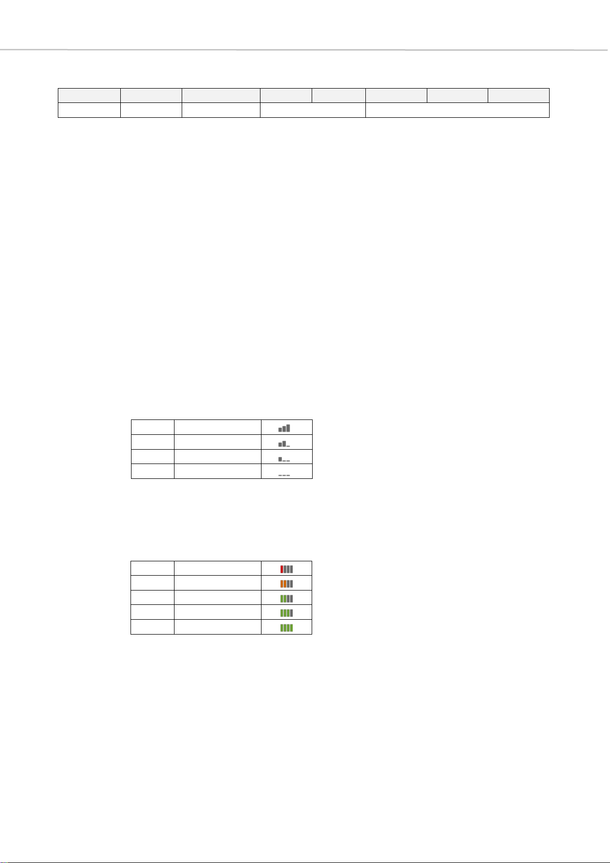
bit 4-3 RF Level: shows RF reception of each MU
>> These two bit positions represent the RF reception of the individual MUs.
As in the graphical representation in the software, a distinction is made
between four different states.
bit 2-0 BatLevel: battery level
>> The battery level is displayed in the Quinta PC software by means of a
vertical bar diagram, where no green bar stands for a state of charge
of 20% and there is an increase of 20% per bar to the maximum state of
charge of 100%.
11
100% RF level
10
66% RF level
01
33% RF level
00
no RF level
000
20% charged
001
40% charged
010
60% charged
011
80% charged
100
100% charged

16 Connectivity and Information Commands
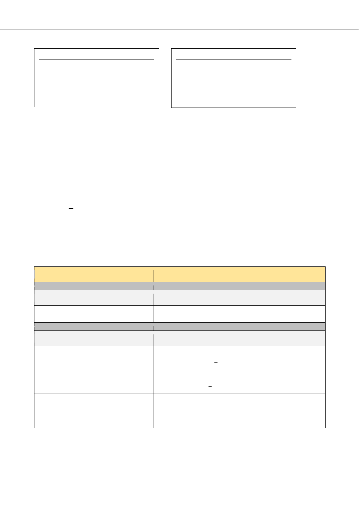
v- Version information
This parameter is represented by six digits. The latter are to be read as hexadecimal
numbers, with a division into four number groups as described in the following section:
digit 1
2
3
4
5
digit 6
FWVersion
FWRevision
FWBuild
Digits 1 and 2 represent the two decimal places of the
PnP version number as
hexadecimal numbers
; to obtain the PnP version number a 1. must be placed in front of
this number.
Digits 3 and 4 represent the
major firmware number including the firmware revision
number
, insofar as digit 3 indicates the major firmware number and digit 4 the revision
number corresponding to the major firmware number. Digits 5 and 6 represent the
firmware build
. All together the firmware information is represented with digits 3 to 6 as
the following: 3.4.56.
Example
Receive: <CR><LF>
X 00021E 0131 7A 241100<CR><LF>
>
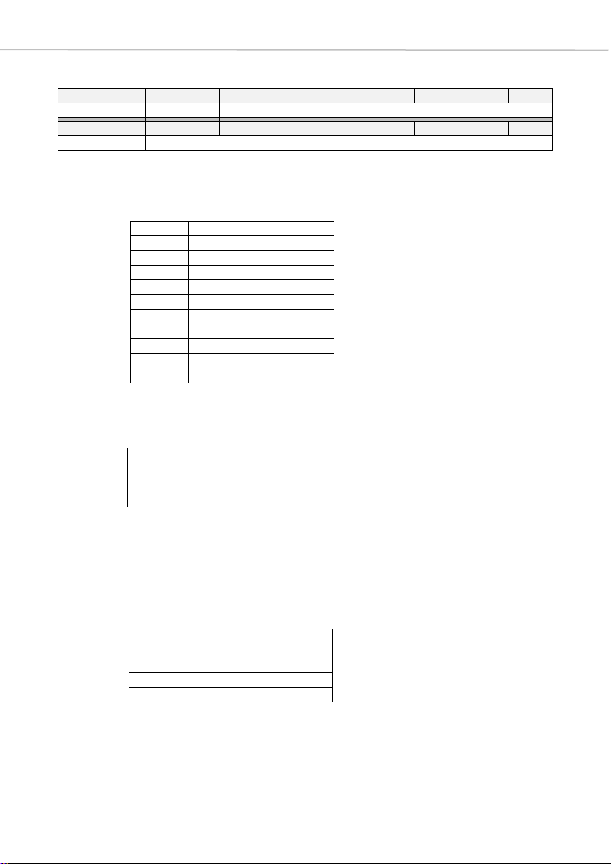
Parameter Explanations
x
command for MU status information
00021E
muad in hex MU ID = 542
0131
HWType: Double MU (2 buttons)
MUZone: 0x3 (corresponds to zone 4 in Quinta PC-software)
AllocationMode (Function): Double Delegate
7A
BatLevel: 60%, best RF level, charger OFF, no error
241100
PnPVersion: 0x24 = 36dec 1.36
FWVersion: 1.1.00
17 System Configuration Commands
3System Configuration Commands
3.1 Fcommand
Changing operation mode
The V A command described in the previous section queries whether the CU is in
conference or microphone mode. Of course, the mode can also be changed using a
corresponding protocol command, which is described below.
Important Note
As already mentioned in chapter 2.2, it is necessary to restart the CU to change the
operation mode successfully. This is done using the ^ command, which is also described
in chapter 2.2.
Examples
Communication direction
Controller -> CU
Syntax
Description
F B 2
Select Microphone Mode
F B 1
Select Conference Mode
Select Microphone Mode
Transmit:
F B 2<CR>
Receive:
<CR><LF>
SwMM<CR><LF>
>
Select Conference Mode
Transmit:
F B 1<CR>
Receive:
<CR><LF>
SwCM<CR><LF>
>
18 System Configuration Commands
3.2 ATTENTION! Use carefully!
M command
Selecting Unicast or Broadcast Mode
You can use the M command to switch between the default broadcast mode and the
unicast mode when directing commands specifically to MUs. In unicast mode, you can
address individual MUs with commands that contain an '~' at the beginning. These
commands differ from commands that already contain an MU ID (muad) in the
parameter set and thus already address an MU directly. ~' in this context means that
the commands are tunnelled through the command structure of the CU and directly
forwarded to the MUs.
Important Note
It is very important to switch back to broadcast mode after using unicast mode.
Otherwise errors with unforeseeable consequences may occur, since all further
commands are executed in unicast mode on the selected MU.
Examples
Communication direction
Controller -> CU
Syntax
Description
M muad
Select Unicast Mode addressing the MU with MU
ID muad
M 0
Select Broadcast Mode
Parameters
Description
muad
MU ID
[range: 0x00000001 0xFFFFFFFF]
Select Broadcast Mode
Transmit:
M 0<CR>
Receive:
<CR><LF>
MUAD=0x00000000<CR><LF>
>
Select Unicast Mode (muad = 0x79B7)
Transmit:
M 79B7<CR>
Receive:
<CR><LF>
MUAD=0x000079B7<CR><LF>
>

19 System Configuration Commands
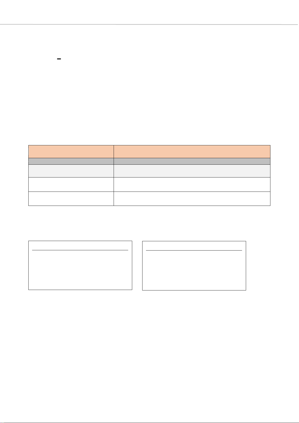
3.3 Jcommands
System Configuration
The J command is used to query and configure important properties of the system. The
following table gives a brief explanation of each command.
Communication direction
Controller -> CU
Syntax
Description
J
gets: Control Status (first line), Speak/Allocation
Mode (second line), MU Button Power Off/Lock
Power Key (LPK) (third line), PIN Status (fourth
line), NOM allowed (fifth line), NOM Override
State (sixth line), Last Mic Hold Status (LMH)
(seventh line)
>>>> In brackets behind the states, which are
queried, the line is indicated, under which they
are to be found with uses of the J command.
J 1 n
sets: Control Mode
n: (0 = Stand-alone / 1 = PC-controlled)
>>>> This command is used to set whether the
system is operated in stand-alone mode or
via PC-controlled mode.
J 4 n
sets: PIN State
n: (0 = Disable / 1 = Enable)
>>>> This command is used to set whether the PIN
protection of the system is enabled or
disabled.
J 5 n
sets: Override/FIFO State
n: (0 = Disable / 1 = Enable)
>>>> This command is used to set whether MUs can
be kicked out according to the first in first out
(FIFO) principle when the maximum number of
active MUs has already been reached. If the
function is deactivated, MUs can only switch
on until the NOM (number of open micro-
phones) is exhausted. If the latter occurs,
the system rejects a speech request and does
not switch off the microphone of another MU.

20 System Configuration Commands
J 6 n
sets: NOM (number of open microphones)
n: (1 4)
>>>> This command sets how many active MUs
resp. open microphones are currently allowed.
n stands for the maximal number of open
microphones.
In order to be able to execute the limitation to
the number of active MUs specified with this
command, the function of the maximum
number of MUs must first be activated with
the command J 9 n.
J 8 n
sets: RF Mode
n: (0 = Auto / 1 = Manual, fix channel)
>>>> This command is used to set whether the RF
mode is set automatically depending on the
reception situation or whether a fixed channel
is selected.
J 9 n
sets: global NOM
n: (0 = use NOM in allocation /
1 = NOM globally disabled)
>>>> This command is used to activate the function
of limiting the active MUs.
J A n
sets: Speak/Allocation Mode
n: (0 = Toggle / 1 = Push To Talk /
3 = Voice Activation)
>>>> This command is used to set how the
microphone units can dial into the system.
J B n
sets: MU Button Power Off/Lock Power Key (LPK)
n: (0 = Deactivate / 1 = Activate)
>>>> This command is used to set whether the MUs
can be switched off via the MU button or not.
When the J command is called, this status is
displayed under LPKdisabled or LPKenabled.
J C m
sets: Priority Mode
m: see table in the following
>>>> This command is used to set which function is
assigned to the function key of the chairman
station. The assignment, which is referred to
as "Normal", is a normal clearing of all
microphone units that are active at this time.
The other so-called priority modes are listed in
the small table under m and explained in the
further course of the document.
This manual suits for next models
2
Table of contents
Popular Media Converter manuals by other brands


Bose
Bose FreeSpace E-4 owner's guide

Texas Instruments
Texas Instruments TPS61041 manual

Matrox
Matrox Monarch HD quick start guide

Beijer Electronics
Beijer Electronics BoX2 extreme installation manual

AceCom Networks
AceCom Networks VCL-4 Ethernet over 1E1 Data sheet & user manual

MD
MD mXion DRIVE-SR user manual

Allen-Bradley
Allen-Bradley Rockwell Automation 842E-SIP Series user manual

Extron electronics
Extron electronics CVC 100 user guide

Zhejiang Uniview Technologies
Zhejiang Uniview Technologies DVS4016-IN quick guide

Baumer
Baumer HOG 86 Mounting and operating instructions

ABB
ABB ACS 600 MultiDrive Safety and product information

TRENDnet
TRENDnet TFC-1000S40D5 Specifications