AceCom Networks VCL-4 Ethernet over 1E1 Instruction Manual

1
AceCom Networks Pte Ltd.
VCL-4 Ethernet over 1E1
E1/4*10/(100) Base-T Interface Converter
Data Sheet & User Manual
AceCom Networks Pte Ltd.
200 Jalan Sultan, Textile Centre,
S 199018
#02-13
ingapore
Phone: +65 6295 3233, Fax: +65 6295 3133
E-mail: [email protected]
Web Site: http://www.acecomnet.com
AceCom Networks
AceCom Networks

The VCL-4 Ethernet over E1 Converter provides
the user a facility to transport Ethernet (multiple
LANs)overanE1link.Theequipmentconvertsand
transports upto 4 x Ethernet links over an E1 in a
shared* mode, or a discrete** mode, depending on
theuser'spreferenceandselection.
*In shared mode: All 4 Ethernet channels are
transported over the same shared E1 link and are
allowed full access to each other's path. The user
may select this mode if the user desires that all of the 4 x Ethernet links that are being transported
overthesameE1tooptimallyshareitsbandwidthresourcesandwherediscretionisessential.
*In discrete mode: All 4 Ethernet channels are transported over the same E1 link, but without
allowingintrusionoraccesstoeachother'spath.Theusermayselectthediscrete*modewhenthe
user desires to transport all 4 Ethernet channels over the same E1 line discretely, and without
allowingaccesstoeachother.
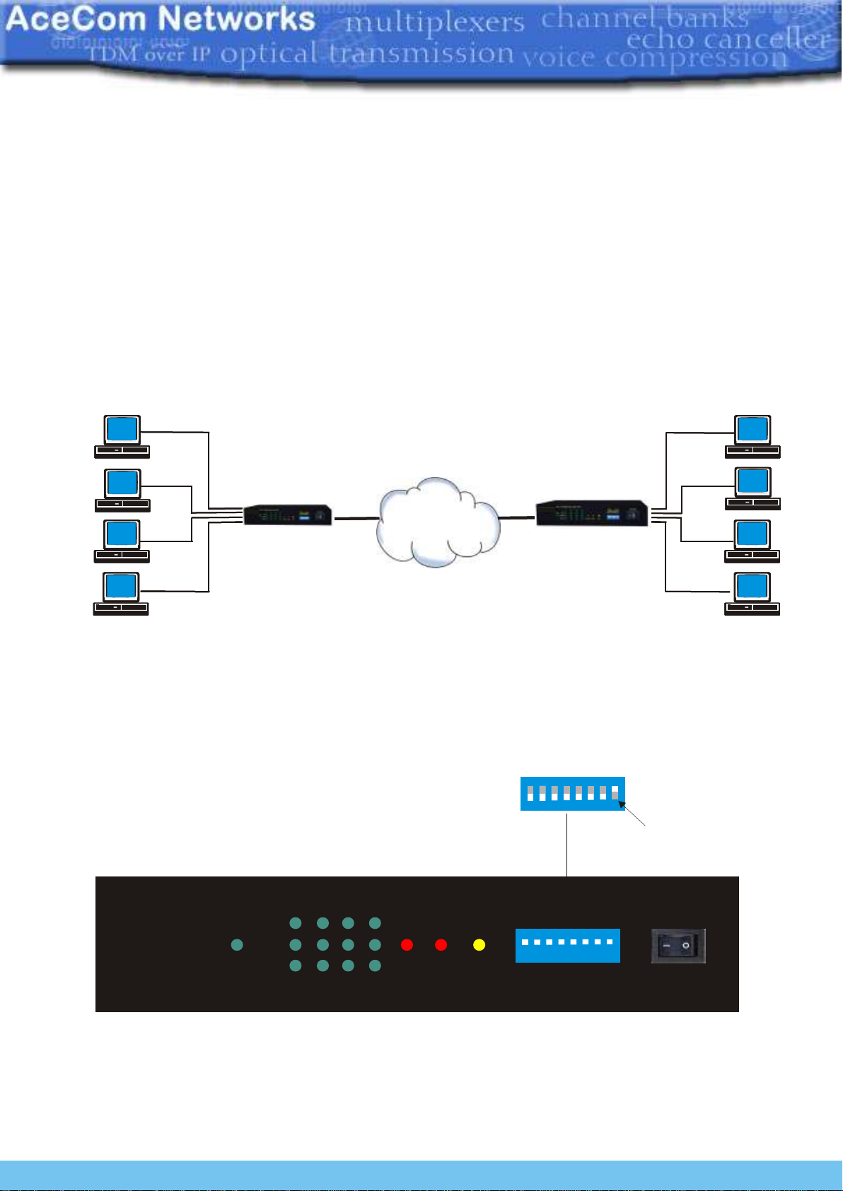
The equipment shall always be installed and used in pairs, with one terminal being installed at
eitherend(eachside)ofthenetwork.
The VCL-4 Ethernet over E1, E1/4*10(100)Base-T Interface Converter is an ethernet extension
device utilizing TDM telecom infrastructure (the telecom network of E1s, or of PDH, SDH and
E1/E3/SDHmicrowaveetc.carryingE1s).
The VCL-4 Ethernet over E1, E1/4*10(100)Base-T Interface Converter converts the Ethernet
Data into E1 frame format for transmission over the existing TDM (E1) links and then re-converts
theE1sbackintoEthernetDataatthefar-endterminal.ItfunctionistoprimarilyprovideaBRIDGE
between two Ethernet LANs over the existing E1 based telecom network. The device can
effectively utilize the redundant bandwidth of telecom operators' existing TDM network to
transportEthernetdatawithlowinvestment.
*Optional powers 220V AC and -48V DC. May be ordered with either power option.
Description
Applications
Thisequipmentmaybeusedforthefollowingpurposes:
1. Bridging Ethernet LANs over existing TDM (E1) telecom network. Extending Ethernet
Networks utilizing TDM (E1) landline based telecom infrastructure.
2. UsingtelecomnetworkofE1s/PDH/SDHMicrowaveetc.carryingE1stotransportEthernet
Data.
In all these cases the equipment be always installed and used in pairs, with one terminal being
installed at either end (each side) of the network.
VCL-4 Ethernet over 1E1
2
AceCom Networks Pte Ltd.

Sharedlinkmode
In the "shared link mode", each LAN can view and talk to other LANs. Example: each LAN
can view and talk to all other LANs at same site or the corresponding remote side. This mode
may be selected for use if bandwidth optimization and usage is of prime importance and the
userisnotaversetosharingtheE1linkresourceswiththeotherLANsbeingtransportedonthe
sameE1link.
For example all four Ethernet Ports at local site are in LAN Mode and will also communicate to
allfourEthernetPortsatfarendsite.
Typical Application
Note: In the "shared link mode", the VLAN switch must be OFF (The ethernet ports are not
isolated to each other on both sides of the E1 link).
Note: Each DIP Switch is ON in downside and OFF in Upside.
VLAN
Switch OFF
POWERPOWER
PWR
VCL-4 Ethernet over 1E1
1 2 3 41 2 3 4
LINK
10/100M
Dup/Col E1LOS E1SYL AIS 1 2 3 4 5 6 7 8
Application Diagram of VCL-4 Ethernet over 1E1
Converter in V LAN Mode “shared link mode”
E1Network
LAN 1LAN 1
LAN 2LAN 2
LAN 3LAN 3
LAN 4LAN 4
PC PCPC PC
PC PC
PC PC
PC PCPC PC
PC PCPC PC
E1 E1
E1/4*10(100)Base-T
Interface Converter E1/4*10(100)Base-T
Interface Converter
E1Network
LAN 1LAN 1
LAN 2LAN 2
LAN 3LAN 3
LAN 4LAN 4
PC PCPC PC
PC PC
PC PC
PC PCPC PC
PC PCPC PC
E1 E1
E1/4*10(100)Base-T
Interface Converter E1/4*10(100)Base-T
Interface Converter
3
AceCom Networks Pte Ltd.

POWERPOWER
PWR
VCL-4 Ethernet over 1E1
1 2 3 41 2 3 4
LINK10/100M
Dup/Col
E1LOS
E1SYLAIS
1 2 3 4 5 6 7 8
POWERPOWER
PWR
VCL-4 Ethernet over 1E1
1 2 3 41 2 3 4
LINK
10/100M
Dup/Col E1LOS E1SYL AIS
POWER
1 2 3 4 5 6 7 8
CLK
RLP
O
U OA T
SPD
DPX
SPDL1
SP L2D
L N
VA
Discretelinkmode
Inthe"discretelinkmode"eachLANisbridgedto,andcanonlytalktoitscorrespondingLAN
onthe remoteside. Itcannottalkto anyother LANeither atsameside orthe remoteside.This
mode may be selected for use if the users do not wish to share the E1 link resources with the
otherLANsbeingtransportedonthesameE1link.
ForexampletheEthernetPort1(atlocalsite)willcommunicatetoEthernetPort1atfarendsite
andsoonforPort2etc.
Example:Inthediscretelinkmode,theLAN1(EthernetPort1oftheequipment)onlycantalk
to the corresponding LAN 1 (Ethernet Port 1 of the equipment) at remote side and can not talk
toanyotherLAN,eitheronremotesideorsameside.
Note: In the discrete link mode, the VLAN switch must be ON (Ethernet Ports isolated) in
Boththeunits.
Note: Each DIP Switch is ON in downside and OFF in Upside.
VLAN
Switch ON
Application Diagram of 4 Ethernet ver E1VCL- o 1
Converter in “discrete link mode”
E1Network
LAN 1LAN 1
LAN 2LAN 2
LAN 3LAN 3
LAN 4LAN 4
PC PCPC PC
PC PC
PC PC
PC PCPC PC
PC PCPC PC
E1 E1
E1/4*10(100)Base-T
Interface Converter E1/4*10(100)Base-T
Interface Converter
4
AceCom Networks Pte Ltd.

Technical Features
1. The maximum transmission rate of 4 Ethernet data over E1 links is 2.048 Mbit/s
2. Supporting 1600 long frames, accordance with Interior Switching Link (ISL) Protocol
3 Supporting local E1 port loop-back
4. The Ethernet Port is self-adaptive to crossover or shoot-through (Straight/Parallel)
cable to avoid the trouble of re-wiring
5. Supports up to four Ethernet Ports. Supports port mask
6. Ethernet negotiation function. Supports 10M/100M and working modes of both
full-duplex and semi-duplex
7. Transparently transmits ultra-long frames stipulated in IEEE 802.1Q, and supports
Ethernet switches with VLAN function
8. Imbedded, dynamic Ethernet MAC address list (1024 addresses), and filter function for
local data frames
9. Can support multiple LANs of different network addresses
10. Optional powers 220V AC and -48V DC. May be ordered with either power option.
E1 Port specifications
Ethernet Port specifications
NumberofE1Ports One
LineRate E1 (2.048Mbps±50bps)
Framing Un-Framed
Electrical AsperITU-TG.703
Jitter AsperITU-TG.823
Impedance 120Ohm(RJ-45)
Impedance 75 Ohm (BNC)
NumberofPorts Four
PortTypes 10/100BaseT(Auto-negotiating)
StandardsCompliance IEEE802.3
Data Rate 10/100BaseT transmission rate limited
to 2.048Mbps (maximum)
Connectors RJ-45 (10/100 BaseT Electrical)
5
AceCom Networks Pte Ltd.

Installation and Commissioning
1. Qualifyingthenetwork
The time-slots should be configured according to the planning of E1 link. If the
accessed E1 link is being exclusively and only by this equipment (i.e. VCL-4 Ethernet
over E1, E1/4*10(100)Base-T Interface Converter), it should be configured as
transparent transmission to increase Ethernet service bandwidth
*** Note: Due care must be taken to ensure that the settings meet the user
requirements of “shared line" or "discrete line" service
The remote time-slots shall be configured in accordance with the local time-slots. The
configuration of the equipment on both sides should be the same
The length of the Ethernet cable shall not exceed 100m
2. Grounding
When the equipment is used with the AC~220V power supply, the 3-core socket must
be grounded for protection
The other equipment (e.g. optical terminal) connected with this equipment must also
be grounded to earth for protection
3. Installation
Step1 PoweruptheEthernetoverE1(IPoTDM)equipment.
Important: Please ensure that Ethernet over E1 (IPoTDM) equipment is powered-up prior to
connectingtheethernetandtheE1links.
Step 2 Connect E1 line after ensuring that transmission device, port converter and ethernet
switchhavebeengrounded.
ABitErrorRate(BER)testmaybe conductedonE1linkusingaBERTtestertoensurethat the
E1errorsarewithinthepermittedlimits/threshold.
Step 3 Please configure the Ethernet Mode of the Ethernet over E1 (IPoTDM) equipment at
both sides as well as the Ethernet Ports of the devices that are connected to the Ethernet over
E1(IPoTDM)equipment.Connecttheethernetlinks.
The equipment is used to bridge Multiple LANs. Please ensure that the connecting LANs on
bothsidesofthelinkareoperatinginthesameIPdomain.
Step 4 Ping over the ethernet connection from one side to the other (near-end to the far-
end) to verify the link.
Important Note:
Please power-up the equipment prior to connecting the ethernet and the E1 links.
6
AceCom Networks Pte Ltd.

POWERPOWER
PWR
VCL-4 Ethernet over 1E1
1 2 3 41 2 3 4
LINK
10/100M
Dup/Col
E1LOS
E1SYLAIS
1 2 3 4 5 6 7 8
POWERPOWER
PWR
VCL-4 Ethernet over 1E1
1 2 3 41 2 3 4
LINK
10/100M
Dup/Col E1LOS E1SYL AIS
POWER
1 2 3 4 5 6 7 8
L
C K
RLOP
AUTO
PDS
DPX
DSP L1
SPDL2
VLAN
Description of the Front Panel
1. FrontPanel
Outline of the front panel of E1/4*10(100)Base-T Interface converter is as follows.
Power LED: The GREEN LED indicator lights of power supply is lit under normal working
condition when the power supply is connected.
CLK
E1LOS
E1SYL
AIS
RLOP
AUTO
SPD
DPX
SPDL1
SPDL2
VLAN
7
AceCom Networks Pte Ltd.

Definition of Indicators
Status of Ethernet Port LEDs
Indicator light Port 1 Port 2 Port 3 Port 4
Link LED GREEN Input Signal Input Signal Input Signal Input Signal
"ON" (Solid) Detected Detected Detected Detected
Link LED GREEN Receiving/ Receiving/ Receiving/ Receiving/
"ON" (Flashing) Sending Data Sending Data Sending Data Sending Data
10/100M "Green" Port under Port under Port under Port under
100M service 100M service 100M service 100M service
mode mode mode mode
10/100M "OFF” Port under Port under Port under Port under
10M service 10M service 10M service 10M service
mode mode mode mode
Dup/Col "ON" Port under Port under Port under Port under
(Solid) full-duplex full-duplex full-duplex full-duplex
mode mode mode mode
Dup/Col "OFF" Port under Port under Port under Port under
(Solid) semi-duplex semi-duplex semi-duplex semi-duplex
mode mode mode mode
Dup/Col "OFF" Ethernet Port Ethernet Port Ethernet Port Ethernet Port
(Flashing) has detected has detected has detected has detected
any conflict any conflict any conflict any conflict
error error error error
Status of
Indicator light E1 Circuit LED Alarm and status
E1 LOS RED "ON" E1 port is unconnected or bad connected
E1 LOS RED "OFF" E1 port is connected properly
AIS YELLOW "ON" 1's code alarm of E1 line
8
AceCom Networks Pte Ltd.

DIP switch settings on front panel are as follows
Switch Description Default
1 (CLK) ON Internal clock: The system is running on its internal clock ON
OFF Line clock: The system is drawing clock from E1 line.
2 (RLOOP) ON No loop-back on E1 interface. ON
OFF E1 Interface is loop-back.
3 (AUTO) ON Ethernet Port is running in self-adaptive mode. ON
OFF Ethernet Port rate is depend on SPD
4 (SPD) ON Ethernet Port rate is 100M if "AUTO" is off ON
OFF Ethernet Port rate is 10M if "AUTO" is off
5 (DPX) ON Ethernet Port is running in full-duplex mode ON
OFF Ethernet Port is running in semi-duplex mode
6 and 7 Speed Limit configuration of Ethernet Interface
(SPLD 1 SPLD 1 SPLD 2 Port Speed limit ON
and SPLD 2) ON ON None port is speed limit
ON OFF 1 and 2 port speed, limit 512 K; 3 and 4 port, no
Speed limit
OFF ON 1 port speed limit, 1M; 2,3 and 4, no speed limit.
OFF OFF Speed limit, 512 K for all ports
8 (VLAN) ON Ethernet Port isolated (discrete link mode) Off
OFF Ethernet Port is not isolated (Share link mode)
Note: Each DIP Switch is ON in downside and OFF in Upside.
Power supply switch: To switch the power OFF/ON.
2. (A) BackPanel: ACInput
The back panel of the E1/4*10(100)Base-T 4Ethernet Over E1 (IPoTDM) equipment is as
follows with AC Input
ETHERNET
ETHERNET
22VAC 0
ßÏC⇓
ߥ kµ ⇓ß̵•# ⇓ßg zAñ² ⇓
G.703
ߊ⇓
1 2 3 4
1 2 3 4
⇓
ßf¼á‚ ⇓ßö¢Æ=·⇓
ßÅm³ t ⇓
ß³ -b†"⇓
1 2 3 4
9
AceCom Networks Pte Ltd.

DIP switch settings on Back panel
E1 socket for 120 Ωbalanced: All DIP switches MUST be OFF (upside)
E1 socket for 75 Ωunbalanced: All DIP switches MUST be ON (downside)
AC220V: represents the unit usesAC~220V power supply.
*Optional powers 220V AC and -48V DC. May be ordered with either power option.
(B) Backpanel: DC Input
The back panel of the E1/4*10(100)Base-T 4Ethernet Over E1 (IPoTDM) equipment is as
follows with -48V DC Input.
120ΩRJ45 pin-out
PIN No.Definition of function Signal Direction
1 NC
2 TX+ (transmitted data +) E1 Data Output
3 TX- (transmitted data -) E1 Data Output
4 NC
5 NC
6 RX+ (received data +) E1 Data Input
7 RX- (received data -) E1 Data Input
8 NC
E1 RJ-45 Pinouts Details
Ethernet RJ-45 Crossover Pinouts
PIN No.Definition of function Signal Direction
1 TX+ (transmitted data +) Data Output
2 TX- (transmitted data -) Data Output
3 RX+ (received data +) Data Input
4 NC
5 NC
6 RX- (received data -) Data Input
7 NC
8 NC
Ethernet RJ-45 Crossover Pinouts
ETHERNET
ETHERNET
Positive
Negative
Ground
DC 48V
߈U⇓
ßT”Z ⇓ßqŒR⇓ߌ§BÉ⇓
G.703
ßh⇓
1 2 3 4
1 2 3 4
⇓
ß&Ó¦r⇓ß”¦yE ⇓
ß<™_Ÿ⇓
ßRÿá´€ ⇓
1 2 3 4
⇓
DC -48V
++-
++
10
AceCom Networks Pte Ltd.

Time-slot configuration of E1 port: For E1 time-slot configuration, the DIP Switch settings on
the bottom panel are as follows:
The time-slot DIP switches located at the bottom of the equipment marked with TS0~TS31
bits corresponding to 0~31 time-slots of E1 channel.
Note: It is recommended to set the TS0 DIP switch OFF.
3. Bottom Panel:
The Bottom panel of the E1/4*10(100)Base-T 4Ethernet over E1 (IPoTDM) equipment is as
follows.
Working Mode Switch Setting
Unframed All switches are set to OFF
Framed (CCS/PCM-31) S0 set to OFF, and the occupied time slots to ON
Multi-Framed (CAS/PCM-30 ) All switches S0~S31 set to ON but S16 is set to OFF
Example 1: If you wish to use only first 5 time-slots then you need to set the S0 time-slots to
OFFandswitchS1toS5toONandtime-slotS16willbesettoON.
Example 2: Ifyouwishtocarryfirst8time-slotson512Kbps,thenyouneedtosettheS0time-
slotOFFandswitchS1toS8toON(i.e.sinceeachtime-slotconsumes64Kbps,so8time-slots
willconsume8x64Kbps=512Kbps)andtime-slotS16willbesettoON.
Example 3: If you wish to carry 20 time-slots on 1.28Mbps (64Kbps x 20) then you need to set
time slot S0 OFF and S1 to S21 time-slots to ON. Please remember that the time-slot S16 will
beusedassignalingtime-slot.
11
AceCom Networks Pte Ltd.

Installation Instructions and Trouble-shooting
A Installation Instruction
1. Perform the following tests prior to usage:
Inspect every configuration switch on the panels to see whether they are set in normal
working state, i.e. PWR and E1 LOS light ON; in the case of framed E1, E1 SYL shall
be ON, other lights OFF.
2. Arrange E1 line impedance and time-slots as required, plug in E1 input/output lines
and Ethernet line, then turn ON the power supply, the equipment comes into normal
working conditions.
3. One equipment MUST be set to master clock and other MUST be set to line clock
(loop-timed).
B Trouble-shooting
When the equipment is under normal working conditions, the three indication lights, E1LOS
E1SYL and AIS, shall be OFF.
1. Trouble: E1LOS light ON
Check point: make E1 loop-back at E1 input port and output port, if the light OFF,
then highlight the check on E1 input line. Please check with the E1 Cable.
2 Trouble: E1SYL light ON
Check point: Make E1 loop-back at E1 input port and output port, if the light OFF,
then highlight the check on the opposite-end interface converter to see whether set to
framing service mode. If the opposite side interface converter has been set to framing
service mode, check the transmission path of E1 for any disconnect. The alarm is valid
if port is working on framing mode.
3. Trouble: AIS light ON
Check point: normally this fault is due to either of the following reasons:
1. The opposite-end E1 equipment cuts off receiving.
2. There are other devices working under test on E1 transmission line.
3. E1 Channel is in loop-back state.
12
AceCom Networks Pte Ltd.

4. Trouble: LINK light OFF
Check point: This fault is basically due to the error in making network (crossover or
straight-through) cable. Please check if the equipment I require crossover cable or
straight-through cable you are connecting to. VCL-4 Ethernet over E1 is
self-adaptive to crossover or straight-through cable.
5. Trouble: LINK light in normal state, but data PING fails
Check point:
1. Check whether the state of the equipment Ethernet is in accordance with that
of the opposite-end Ethernet; If not then, cancel the self-adaptive state of
Ethernet Interface and change compulsorily to configure speed and duplex
so as to be in accordance with the other end.
2. Check whether the equipment E1 port or E1 transmission channel is under
loop-back or other test conditions, if any, then cancel it.
3. Check whether the time slot configuration of the local equipment is in
accordance with the remote one. If not then, configure it to be in accordance.
6. Trouble: Data succeed in PING, but with frame loss
Check point: This fault may be due to the following reasons:
1. Incompatible configuration of E1 port impedance.
2. Incomplete physical connection of E1 port, e.g. only one pole connected at
receiving end.
3. Wrong configuration of clock, change the clock to master clock.
7. Trouble: The communication is normal prior to configure port mask, but blocked after
port mask configuration.
Check point: Ensure whether the remote equipment also configured port mask,
whether the port mask configuration at two ends is in accordance; after port mask
configuration, only Ethernet of same port number can perform communications. Check
whether VLAN switch set to OFF (shared link mode is ON) the equipment connected
to Ethernet interface, if any, Toggle the VLAN switch to ON (set the equipment for
discrete link mode).
General
1. Power Supply
AC Mains Input : 220V 20% (AC Mains input model).
*Optional powers 220V AC and -48V DC. May be ordered with either power option.
Power Consumption: 10W
2. Service Conditions
0 0
Working temperature: -5 C ~ +50 C
0 0
Storage temperature: -20 C ~ +70 C0
Relative humidity: 5 % ~ 95% (at 35 C)
Do not subject the equipment to corrosive solvents, gas, dust or intense magnetic-field
interference.
13
AceCom Networks Pte Ltd.

3. Dimensions : 48cm x 4.3cm x 16cm
4. Weight : 2 Kgs.
Note: Operation and maintenance of network equipment require professional knowledge
and experience. We recommend the equipment to be managed only by qualified
technicians. Should you require technical assistance please consult the provider, or contact
Technical specifications are subject to changes without notice.
Windows is the registered Trademark of Microsoft Corporation, USA.
Revision 07 - May 27, 2030.
AceCom Networks Pte Ltd.
200 Jalan Sultan, Textile Centre,
S 199018
#02-13
ingapore
Phone: +65 6295 3233, Fax: +65 6295 3133
E-mail: [email protected]
Web Site: http://www.acecomnet.com
14
AceCom Networks Pte Ltd.
Table of contents