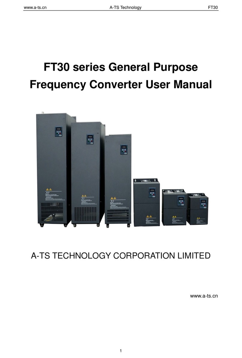
A-TS TECHNOLOGY FT50 Series User manual

www.a-ts.cn A-TS Technology FT50
1
FT50 series General Purpose
Frequency Converter User Manual
A-TS TECHNOLOGY CORPORATION LIMITED
www.a-ts.cn

www.a-ts.cn A-TS Technology FT50
2
DECLARATION
Without written permission, reprint or copy is strictly forbidden. Unauthorized copying,
dissemination or use of this document and its contents is prohibited. Violators will be liable for
compensation.
All rights, including the rights granted by patent rights and the registration rights of application
models or designs will be reserved.
The information provided in this publication will be updated regularly, and any necessary
corrections will be implemented in subsequent releases. Suggestions for improvement are
welcome at any time.
Version
Product
Release Date
Note
V-21-01
FT50
29.07.2021
N/A

www.a-ts.cn A-TS Technology FT50
3
TABLE OF CONTENTS
TABLE OF CONTENTS............................................................................................................ 3
1 FUNDAMENTAL SAFETY INSTRUCTIONS......................................................................... 5
1.1 Alarm Sign and Description.......................................................................................... 5
1.2 Safety Instructions........................................................................................................ 7
1.3 Special Warnings........................................................................................................ 10
2 PRODUCT PROFILE ........................................................................................................... 14
2.1 FT50 series Frequency Converter Features and Advantages ................................... 14
2.2 Model Designation...................................................................................................... 15
2.3 Technical Data............................................................................................................ 15
2.4 Dimension Specification............................................................................................. 17
2.4.1 Overall Dimensions.......................................................................................... 17
2.4.2 Outline Dimensional Drawing........................................................................... 19
2.4.3 Flange Mounting Dimension, for models from 15kW to 160kW ...................... 22
2.4.4 Bottom Mounting Bracket Dimension............................................................... 24
3 INSTALLATION AND WIRING............................................................................................ 25
3.1 Installation Condition.................................................................................................. 25
3.1.1 Use the Frequency Converter after Long-term Storage .................................. 25
3.1.2 Installation Environment................................................................................... 25
3.1.3 Installation Space............................................................................................. 26
3.2 Installation Guide........................................................................................................ 28
3.2.1 Wall-mounted Installation................................................................................. 29
3.2.2 Flange Mounting .............................................................................................. 30
3.2.3 Cabinet Installation........................................................................................... 31
3.2.4 Cover Plate Uninstallation and Installation ...................................................... 34
3.2.5 The Operation Panel Installation...................................................................... 36
3.3 Terminals and Wiring.................................................................................................. 40
3.3.1 Standard Wiring Diagram................................................................................. 40
3.3.2 Main Circuit Terminal Function Description...................................................... 41
4 OPERATION PANEL........................................................................................................... 45
4.1 Operation panel description ....................................................................................... 45
4.2 LED Operation Panel ................................................................................................. 45
4.2.1 Panel Keys....................................................................................................... 45
4.2.2 Indicator Light................................................................................................... 46
4.2.3 Check and modify the parameter function code .............................................. 47
4.2.4 Check Parameter Function Code..................................................................... 48
4.2.6 Fault and Alarm Display................................................................................... 50
4.2.7 Keyboard Password Lock Function ................................................................. 50
4.2.8 Parameter Upload and Download Function..................................................... 51
4.2.9 Remote Operation of the Operation Panel....................................................... 51
5 COMMISSIONING GUIDE................................................................................................... 52
5.1 Quick Commissioning Guide...................................................................................... 52
5.2 Power On ................................................................................................................... 55

www.a-ts.cn A-TS Technology FT50
4
5.3 Parameter Initialization............................................................................................... 55
5.4 Motor Control Mode Selection.................................................................................... 56
5.5 Start and Stop Commands......................................................................................... 56
6 SYSTEM PARAMETERS..................................................................................................... 60
6.1 Parameter Description................................................................................................ 60
6.2 Interconnection Parameter Function.......................................................................... 62
6.2.1 Interconnection Parameter Setting Method ..................................................... 62
6.2.2 Interconnection Parameter Control Word and Status Word ............................ 62
6.3 Parameter List............................................................................................................ 63
7 FAULT DIAGNOSIS AND HANDLING................................................................................ 65
7.1 Safety Precautions ..................................................................................................... 65
7.2 Adjustment Guide before the Test Run ...................................................................... 65
7.3 Restart the Frequency Converter after a Fault .......................................................... 68
7.4 Common Faults and Trouble Shooting....................................................................... 69
8 ROUTINE MAINTENANCE.................................................................................................. 72
8.1 Routine Maintenance ................................................................................................. 72
8.2 Regular Inspection ..................................................................................................... 72
8.3 Fan Replacement....................................................................................................... 73
8.4 Storage and the Maintenance.................................................................................... 76
8.4.1 Storage............................................................................................................. 76
8.4.2 Maintenance..................................................................................................... 76
9 SYSTEM DEVICE SELECTION........................................................................................... 77
9.1 FT50 series Frequency Converter Connection Diagram ........................................... 77
9.2 Optional Devices List.................................................................................................. 78
9.3 Brake Component Selection Instructions................................................................... 80
9.3.1 Brake Components for Models of 75kW and below......................................... 80
9.4 Motor Selection Guidelines ........................................................................................ 80
9.5 Peripheral Equipment Selection Guidelines............................................................... 81
10 EXPANSION BOARDS...................................................................................................... 84
10.1 Expansion Board Installation.................................................................................... 84
10.2 Expansion Board Function Description.................................................................... 85
APPENDIX .............................................................................................................................. 86
THE END .............................................................................................................................. 87

www.a-ts.cn A-TS Technology FT50
5
1 Fundamental Safety Instructions
This manual provides guidance on safety precautions, product specifications, installation and
wiring, keyboard operation, parameter settings, alarms, trouble-shooting, routine maintenance
etc. It doesn’t include all the security matters or considerations.
All the local laws, regulations, and codes of practice should be obeyed first, besides the
instructions in the manual.
For any injury or loss caused by improper operation, the A-TS technology will not take the
responsibility. The A-TS technology is not legally bound in any manner either.
Disclaimer of Liability
We have reviewed the contents of this publication to ensure consistency with the hardware
and software described.
Since variance cannot be precluded entirely, we cannot guarantee full consistency. However,
the information in this publication is reviewed regularly and any necessary corrections are
included in subsequent editions.
1.1 Alarm Sign and Description
This manual contains notices you have to observe in order to ensure your personal safety, as
well as to prevent damage to property. The notices referring to your personal safety are
highlighted in the manual by a safety alert symbol, notices referring only to property damage
have no safety alert symbol. These notices shown below are graded according to the degree
of danger. If more than one degree of danger is present, the warning notice representing the
highest degree of danger will be used. A notice warning of injury to persons with a safety alert
symbol may also include a warning relating to property damage.
Dangers might not be recognized if warning labels are missing or illegible. Unrecognized
dangers may cause accidents resulting in serious injury or death.
Check that the warning labels are complete based on the documentation.
Attach any missing warning labels to the components, where necessary in the national
language.
Replace illegible warning labels.
CAUTION
To have a thorough understanding, please read this manual carefully and follow all
the safety instructions and warning before moving, installing, operating and
maintaining the frequency converter. Make sure the warning sign is placed in the
conspicuous position.

www.a-ts.cn A-TS Technology FT50
6
DANGER
The danger sign indicates that death or severe personal injury will result if proper
precautions are not taken.
WARNING
The warning sign indicates that death or severe personal injury may result if proper
precautions are not taken.
CAUTION
The caution sign indicates that minor or moderate personal injury can result if
proper precautions are not taken.
NOTICE
The notice sign indicates that property damage can result if proper precautions are
not taken.
PROMPT
The prompt sign indicates that undesirable results or conditions may occur if the
user does not pay attention to the prompt message.
EXPLICATION
The explication sign indicates the important information about the product, and the
parts in bold are points that require special attention.
Qualified Personnel
The product/system described in this documentation may be operated only by
personnel qualified for the specific task in accordance with the relevant
documentation, in particular its warning notices and safety instructions.
Qualified personnel are those who, based on their training and experience, are
capable of identifying risks and avoiding potential hazards when working with these
products/systems. And he/she should also be trained in first aid.
PE: Protective Earthing by the grounding conductor. The cross-sectional size
of the grounding conductor should be able to ensure that the voltage of the
earth point does not exceed 50 volts when the PE ground point is short
connected to the ground bus. Usually, this point is used for the earth point of
the frequency converter.

www.a-ts.cn A-TS Technology FT50
7
1.2 Safety Instructions
When working with FT50 series frequency converter and related systems, the Warning,
Caution, Notice and Prompt listed in this section are usually involved.
The special Warning, Caution, Notice and Prompt are suitable for special operations. They
are placed at the beginning of the related chapter, and repeated or supplemented where
necessary in the chapter.
Please read these Warning, Caution, Notice and Prompt carefully. They provide you with
guidelines for the protection of personal safety and help to extend the service life of the FT50
series frequency converter and the equipment connected to it.
Proper transport, storage, installation, assembly, commissioning, operation and maintenance
are required to ensure that the products operate safely and without any problems. The
permissible ambient conditions must be complied with. The information in the relevant
documentation must be observed.
-The earth point. The voltage reference of the earth point can reach the
same as the ground voltage. Usually, this point is used to ground the motor.
WARNING
This equipment carries dangerous voltage, and it controls potentially
dangerous rotating parts. If you do not follow the Warning regulations, or do
not operate in accordance with the requirements of this manual, it may cause
death, serious personal injury or major property damage.
Only qualified professionals are allowed to operate this equipment, and
before using the equipment, be familiar with all the safety instructions and
regulations on installation, operation and maintenance in this manual.
Pay attention to the risk of electric shock. Even if the power supply has
been cut off, there is still dangerous voltage on the DC circuit capacitor of the
frequency converter. Therefore, it is only allowed to open the device 10
minutes later after the power supply is turned off.
Even when the frequency converter is not working, the following terminals may
carry dangerous voltage:
- Power supply terminal R, S, T
- Motor connection terminal U, V, W
- Depends on the frame size, terminal +, -, BR
CAUTION
Prevent children and the public from touching or approaching this device.
This equipment can only be used for the purpose specified by the
manufacturer. Unauthorized modification or use parts and accessories not sold
or recommended by the manufacturer of this equipment may cause fire,
electric shock and other injuries.

www.a-ts.cn A-TS Technology FT50
8
About transportation and storage
About commissioning
About operation
PROMPT
Please put this manual in an easy-to-find place near the frequency converter to
ensure that it is convenient for all users.
Before installing and debugging the frequency converter, please read these
safety rules and warnings carefully, as well as all warning signs on the
equipment. Ensure that warning signs are placed in a prominent place, and
replace signs that have fallen off or are damaged.
CAUTION
During transportation and storage, it is necessary to ensure that the frequency
converter is not subjected to physical shock or vibration, and it must be
protected from rain and not placed in a place where the ambient temperature is
too high.
WARNING
The input power cord can only be permanently tightly connected. The
equipment must be grounded (in accordance with IEC 536 Class 1, NEC and
other applicable standards).
Even when the frequency converter is not working, the following terminals may
carry dangerous voltage:
- Power supply terminal R, S, T
- Motor connection terminal U, V, W
- Depends on the frame size, terminal +, -, BR
This equipment cannot be used as an emergency shutdown device. (refer to
EN 60204, 9.2.5.4)
CAUTION
The power cables, motor cables and control cables connected to the frequency
converter must be connected in a standardized manner to avoid inductive and
capacitive interference caused by the frequency converter.
WARNING
FT50 series frequency converter operates under high voltage.
Dangerous voltage exists on some parts of the electrical equipment during
operation.
According to the EN60204/IEC204 (VDE0113), the emergency shutdown
device must maintain controllability in all working modes of the control
equipment. No matter how the emergency shutdown device stops operating, it
cannot cause uncontrollable or unexpected restarts.
No matter where the fault occurs in the control equipment, it may cause major

www.a-ts.cn A-TS Technology FT50
9
About maintenance
About disassembly and waste disposal
equipment damage or even serious personal injury (that is, there is a
potentially dangerous failure). Therefore, additional external precautions must
be taken or additional devices used to ensure safe operation must be installed,
even when a failure occurs (for example, install the independent current limit
switch, mechanical interlock, etc.)
After the input power is interrupted and powered on again, certain parameter
settings may cause the frequency converter to restart automatically.
In order to ensure that the motor overload protection operates correctly, the
motor parameters input to the frequency converter must be completely
consistent with the motor actually connected.
In order to ensure that the motor I2t over temperature protection operates
correctly, the motor parameters input to the frequency converter must be
completely consistent with the motor actually connected.
The motor over temperature protection function is provided in the frequency
converter. As per the P0426.M parameter setting, the I2t over temperature
protection function is activated by default. By setting the parameter P0426.M to
2-4, the motor over temperature protection function can also be performed by
using the external PTC via the IO expansion board temperature detection
input. Or it can be achieved by comparing the actual temperature measured by
the KTY84 sensor with the fault temperature set by the parameter P0428.M.
This equipment cannot be used as an emergency shutdown device. (refer to
EN 60204, 9.2.5.4)
WARNING
Any faulty parts and devices must be replaced with corresponding spare parts.
Before opening the equipment for maintenance, make sure to disconnect all
the power supplies, and wait for 10 min.
NOTICE
The packaging box of the frequency converter can be reused. Please keep the
packaging box for future use or return it to the supplier.
Easy removable screws and quick connectors are parts that facilitate you to
disassemble the device. You can recycle these disassembled parts and
dispose of them according to the requirements of local authorities, or return
them to the supplier.

www.a-ts.cn A-TS Technology FT50
10
1.3 Special Warnings
DANGER
Electric shock and danger to life due to other energy sources.
Touching live components can result in death or severe injury.
Only work on electrical devices when you are qualified for this job.
Always observe the country-specific safety rules.
Generally, the following steps apply when establishing safety:
1. Prepare for disconnection. Notify all those who will be affected by the
procedure.
2. Isolate the drive system from the power supply and take measures to
prevent it being switched back on again.
3. Wait until the discharge time specified on the warning labels has elapsed.
4. Check that there is no voltage between any of the power connections, and
between any of the power connections and the protective conductor
connection.
5. Check whether the existing auxiliary supply circuits are de-energized.
6. Ensure that the motors cannot move.
7. Identify all other dangerous energy sources, e.g. compressed air, hydraulic
systems, or water. Switch the energy sources to a safe state.
8. Check that the correct drive system is completely locked.
After you have completed the work, restore the operational readiness in the
inverse sequence.
DANGER
Risk of electric shock and fire from supply networks with an excessively high
impedance.
Excessively low short-circuit currents can lead to the protective devices not
tripping or tripping too late, and thus causing electric shock or a fire.
In the case of a conductor-conductor or conductor-ground short-circuit, ensure
that the short-circuit current at the point where the converter is connected to
the line supply at least meets the minimum requirements for the response of
the protective device used.
You must use an additional residual-current device (RCD) if a
conductor-ground short circuit does not reach the short-circuit current required
for the protective device to respond. The required short-circuit current can be
too low, especially for TT supply systems.
Risk of electric shock and fire from supply networks with an excessively low
impedance.
Excessively high short-circuit currents can lead to the protective devices not
being able to interrupt these short-circuit currents and being destroyed, and
thus causing electric shock or a fire.
Ensure that the prospective short-circuit current at the line terminal of the

www.a-ts.cn A-TS Technology FT50
11
frequency converter does not exceed the breaking capacity (SCCR or Icc) of
the protective device used.
DANGER
Electric shock if there is no ground connection
For missing or incorrectly implemented protective conductor connection for
devices with protection class I, high voltages can be present at open, exposed
parts, which when touched, can result in death or severe injury.
Ground the device in compliance with the applicable regulations.
Electric shock due to connection to an unsuitable power supply
When equipment is connected to an unsuitable power supply, exposed
components may carry a hazardous voltage. Contact with hazardous voltage
can result in severe injury or death.
Only use power supplies that provide SELV (Safety Extra Low Voltage) or
PELV (Protective Extra Low Voltage) output voltages for all connections and
terminals of the electronics modules.
Electric shock due to equipment damage
Improper handling may cause damage to equipment. For damaged devices,
hazardous voltages can be present at the enclosure or at exposed
components. If touched, this can result in death or severe injury.
Ensure compliance with the limit values specified in the technical data during
transport, storage and operation.
Do not use any damaged devices.
Electric shock due to unconnected cable shield
Hazardous touch voltages can occur through capacitive cross-coupling due to
unconnected cable shields.
As a minimum, connect cable shields and the conductors of power cables that
are not used (e.g. brake cores) at one end at the grounded housing potential.
Arcing when a plug connection is opened during operation
Opening a plug connection when a system is operation can result in arcing that
may cause serious injury or death.
Only open plug connections when the equipment is in a voltage-free state,
unless it has been explicitly stated that they can be opened in operation.
Electric shock due to residual charges in power components
Because of the capacitors, a hazardous voltage is present for up to 10 minutes
after the power supply has been switched off. Contact with live parts can result
in death or serious injury.
Wait for 10 minutes before you check that the unit really is in a no-voltage
condition and start work.
WARNING
Property damage due to loose power connections
Insufficient tightening torques or vibration can result in loose power
connections. This can result in damage due to fire, device defects or

www.a-ts.cn A-TS Technology FT50
12
malfunctions.
Tighten all power connections to the prescribed torque.
Check all power connections at regular intervals, particularly after equipment
has been transported.
Spread of fire from built-in devices
In the event of fire outbreak, the enclosures of built-in devices cannot prevent
the escape of fire and smoke. This can result in serious personal injury or
property damage.
Install built-in units in a suitable metal cabinet in such a way that personnel are
protected against fire and smoke, or take other appropriate measures to
protect personnel.
Ensure that smoke can only escape via controlled and monitored paths.
Active implant malfunctions due to electromagnetic fields
Frequency converters generate electromagnetic fields (EMF) in operation.
Electromagnetic fields may interfere with active implants, e.g. pacemakers.
People with active implants in the immediate vicinity of a converter are at risk.
As the operator of an EMF-emitting installation, assess the individual risks of
persons with active implants.
Unexpected movement of machines caused by radio devices or mobile phones
Using radio devices or mobile telephones in the immediate vicinity of the
components can result in equipment malfunction. Malfunctions may impair the
functional safety of machines and can therefore put people in danger or lead to
property damage.
Therefore, if you move closer than 20 cm to the components, be sure to switch
off radio devices or mobile telephones.
Damage to motor insulation due to excessive voltages
When operated on systems with grounded line conductor or in the event of a
ground fault in the IT system, the motor insulation can be damaged by the
higher voltage to ground. If the user uses a motor that have insulation that is
not designed for operation with grounded line conductors, the user must
perform the following measures:
IT system: Use a ground fault monitor and eliminate the fault as quickly as
possible.
TN or TT systems with grounded line conductor: Use an isolating
transformer on the line side.
Fire due to inadequate ventilation clearances
Inadequate ventilation clearances can cause overheating of components with
subsequent fire and smoke. This can cause severe injury or even death. This
can also result in increased downtime and reduced service lives for
devices/systems.
Ensure compliance with the specified minimum clearance as ventilation
clearance for the respective component.
Malfunctions of the machine as a result of incorrect or changed parameter settings
As a result of incorrect or changed parameterization, machines can

www.a-ts.cn A-TS Technology FT50
13
malfunction, which in turn can lead to injuries or death.
Protect the parameterization against unauthorized access.
Handle possible malfunctions by taking suitable measures, e.g. emergency
stop or emergency off.
Electrostatic sensitive devices (ESD) are individual components, integrated circuits,
modules or devices that may be damaged by either electric fields or electrostatic
discharge.
Only pack, store, transport and send electronic components, modules or
devices in their original packaging or in other suitable materials, e.g.
conductive foam rubber of aluminum foil.
Only touch components, modules and devices when the user are grounded by
one of the following methods:
Wearing an ESD wrist strap.
Wearing ESD shoes or ESD grounding straps in ESD areas with
conductive flooring.
Only place electronic components, modules or devices on conductive surfaces
(table with ESD surface, conductive ESD foam, ESD packaging, ESD transport
container).

www.a-ts.cn A-TS Technology FT50
14
2 Product Profile
The FT series frequency converter is provided byA-TS Technology Co., Ltd. in China.
They are FT70, FT50 and FT30 series. Power range is from 2.2kW to 355kW.
The FT50 is a standard general purpose frequency converter. It supports V/f control, flux
vector control with and without encoder (Including the speed and torque control). It is widely
used in many industries, such as Metallurgy, Paper making, Textile, Lifting, Chemical, Cable
manufacture, Glass, Printing, Packaging, Food, Pharmaceuticals etc., with high reliability.
The FT30 is an economical general purpose frequency converter. It supports V/f control. It is
also widely used in many industries, such as Construction hoist, Ceramic, Glass, Textile,
Chemical, Rubber, Food, Pharmaceuticals, Fan/Pump, also with high reliability.
2.1 FT50 series Frequency Converter Features and
Advantages
1) Control modes: Closed loop speed control, closed loop torque control, Open loop speed
control, Open loop torque control, V/f Control.
2) Reliable EMC and safety design.
3) Wide range of parameter settings.
4) Easier power supply cable connection.
5) Standard configuration: 2 analog input (AI) channels, 0 - 10V/0 - 20mA. 1 analog output (AO)
channel, 0 - 10V/0 - 20mA.
6) Standard configuration: 6 bipolar digital (on-off) input (DI) channels, 2 digital (on-off) output
(DO) channels, 2 relay output channels.
7) Multiple application macros and powerful programmable function, to meet the needs of
different users.
8) Encoder expansion board supports different output types such as HTL and TTL.
9) Upper machine connection based on RJ45 interface.
10) With analog input and output, digital input and output, built-in PLC, built-in PID regulator,
wobble frequency function, droop control, multi-segment speed function etc.
11) With comprehensive frequency converter and motor protection functions.
12) With a variety of expansion boards, IO expansion board to support relay output and
DI/DO/AI/AO, communication expansion boards to support PROFIBUS-DP, PROFINET, and
Modbus RTU/ASCII, Drive to drive through optical fiber, etc.

www.a-ts.cn A-TS Technology FT50
15
2.2 Model Designation
1 2 3 4
[ 1-2 ] Product Name
FT FT Series Frequency
Converter
50 Standard Frequency
Converter
5689
[ 5 ] Voltage
4380V
10 11 12 13
[ 12 ] Braking Unit
XWith the Standard
Configuration
— —
TF 7
BWith the Optional Built-in
Braking Unit (30KW-
75KW)
14 15
30 Economical Frequency
Converter
[ 3-4 ] Product Series
L X X
T 0 1 5 0 G4
[ 13 ] U/V/W Terminal Type
XStandard U/V/W Terminal
LExtended U/V/W Terminal
[ 14-15 ] Reserved
5 0
[ 6 ] Phase
TThree Phase
[ 7-10 ] Rated Power
0022 2.2KW
0150 15KW
[ 11 ] Type/Mode
GHigh Overload/Constant Torque
PLow Overload/Variable Torque
B
Diagram 2-1 FT50 series Frequency Converter Model Designation
2.3 Technical Data
Table 2-1 Technical data of the FT50 series Frequency Converter
Type
Item
Specifications
Rated input
Input voltage
3AC 380V (±20%)
Frequency
50Hz/60Hz, fluctuation range ±5%
Rated
output
Output voltage
3AC 0 –Usupply (the input voltage)
Maximum output
frequency
500Hz
Operational
control
features
Control modes
V/f , Flux vector control with and without encoder ( Including
the speed and torque control )
Speed range
1:200 (vector control without encoder)
1:1000 (vector control with encoder)
Speed control
accuracy
±0.5% (vector control without encoder)
±0.02% (vector control with encoder)
Torque response
<15ms (vector control with encoder)
Torque control
accuracy
±3% (vector control with encoder)
>10Hz, ±5% (vector control without encoder)
Starting torque
0.25Hz 150% (vector control without encoder)
0Hz 180% (vector control with encoder)
V/F curve
Linear, Square law, Multi-point
Acc/Dec curve
Linear or S shape Acceleration-Deceleration curve
Acc/Dec time
0 - 1200s
Automatic voltage
regulation ( AVR )
Keep the output voltage stable, when the power grid voltage
fluctuates.
Efficiency
≥96%

www.a-ts.cn A-TS Technology FT50
16
Overload capacity
Continuous current allowing 150% of the rated current for
60s every 300s.
Continuous current allowing 180% of the rated current for
5s every 300s.
Carrier frequency
1kHz - 8kHz
Frequency
resolution setting
Digital Setting: 0.01Hz
Analog Setting: Maximum Frequency*0.025%
Analog input
Standard configuration: 2 analog input channels,
0-10V/0-20mA, equipped with +10V, 50mA auxiliary power
supply.
Extended configuration: 1 analog input channel,
0-10V/0-20mA, 1 channel supports PT100/PT1000/KTY84
sensor for Motor over temperature protection.
Analog output
Standard configuration: 1 analog output channel, 0 - 10V/0 -
20mA.
Extended configuration: 1 analog output channel, 0 - 10V/0
- 20mA.
Digital (on-off)
input
Standard configuration: 6 bipolar digital (on-off) input
channels, compatible with active PNP or passive NPN
input. One of them can be used as high-speed pulse input,
the input frequency is up to 100kHz.
Extended configuration: 5 digital (on-off) input channels
Digital (on-off)
output
Standard configuration: 1 high-speed pulse output (optional
to be open collector output), 0 - 100kHz square signal
output, 1 digital (on-off) output channel, maximum output
50mA/24V DC.
Extended configuration: 1 digital (on-off) output channel,
maximum output 50mA/24V DC.
Relay output
Standard configuration: 2 relay output channels, 1A/30V
DC, 3A/250V AC
Extended configuration: 1 relay output channels, 1A/30V
DC, 3A/250V AC
Encoder interface
Supports differential signal, open collector signal, push-pull
signal, etc.
Communication
PROFIBUS-DP, PROFINET-IO, Modbus RTU, Drive to
drive through optical fiber, etc.
Protective function
Over/Under voltage protection, Over current protection,
overload protection, Phase-failure protection (Input and
output), Short circuit protection, Motor over temperature
protection, Motor overspeed protection, No load protection,
Short-circuit braking protection, Braking resistor
short-circuit detection, External DC24V short circuit
protection, etc.

www.a-ts.cn A-TS Technology FT50
17
EMC standard
The EMI complies with IEC 61800-3, Category C3
The EMS complies with IEC 61800-3, Class A
Special
function
Programmable
function
With built-in logic function blocks, and gate, or gate, not
gate, adder subtracter, multiplier-divider, selector, delayer,
RS flip-flop, etc.
Macro program
function
With 6 built-in Application Macros: Standard Macro,
Hand/Auto Macro, Fan/Pump Macro, PID control Macro,
Hoist Macro, Crane Macro
Built-in PID
regulator
PID process closed loop control
Wobble frequency
function
Triangular wave frequency control function for the textile
industry
Droop control
Softens the motor mechanical characteristics, mainly used
in occasions where several frequency converters drive the
same load together.
Other functions
Restart after power failure, Speed tracking, Immunity to
momentary power failure, Multi-segment speed, Built-in
PLC, Slip compensation, Parameter auto-tuning, Torque
limitation, Phase sequence transformation, Frequency
hopping, Torque and speed control mode switching, DC
braking, etc.
Others
Operating ambient
temperature
-10°C - +50°C
+40°C to +50°C, with derating of 1.5% / 1°C
Storage
temperature
-40°C - +70°C
Relative humidity
5% - 95%, No condensation of moisture, No frost allowed
Installation altitude
0 to 1000 m, without derating
1000m to 3000 m, with derating of 1% / 100 m
IP Grade
IP20
Certification
CE
Cooling
Forced air cooling
2.4 Dimension Specification
2.4.1 Overall Dimensions
There are a total of 10 size specification of the FT50 series frequency converter.
Table 2-2 FT50 Series Frequency Converter Model and Dimension
Model
G Type
Dimension
H*W*D ( mm )
Power
( kW )
Input
current
( A )
Output
current
( A )

www.a-ts.cn A-TS Technology FT50
18
FT50-4T0022G-XX
2.2
6.7
5.4
209*130*193
FT50-4T0030G-XX
3
9
7.2
FT50-4T0037G-XX
3.7
12.4
9.8
FT50-4T0055G-XX
5.5
16.7
13
FT50-4T0075G-XX
7.5
24.2
18.8
260*140*186
FT50-4T0110G-XX
11
32.2
25
FT50-4T0150G-XX
15
35
32
350*210*192
FT50-4T0185G-XX
18.5
36
37
FT50-4T0220G-XX
22
43
45
FT50-4T0300G-XX
30
57
60
400*267*220
FT50-4T0300G-BX
30
57
60
FT50-4T0370G-XX
37
69
75
FT50-4T0370G-BX
37
69
75
FT50-4T0450G-XX
45
89
91
542*300*270
FT50-4T0450G-BX
45
89
91
FT50-4T0550G-XX
55
106
112
FT50-4T0550G-BX
55
106
112
FT50-4T0750G-XX
75
139
150
580*338*310
FT50-4T0750G-BX
75
139
150
FT50-4T0900G-XX
90
164
176
FT50-4T1100G-XX
110
196
210
FT50-4T1320G-XX
132
240
253
915*400*315
FT50-4T1600G-XX
160
287
304
FT50-4T2000G-XX
200
365
377
1072*300*500
FT50-4T2000G-XL
200
365
377
FT50-4T2200G-XX
220
410
426
FT50-4T2200G-XL
220
410
426
FT50-4T2500G-XX
250
441
465
1224*330*545
FT50-4T2500G-XL
250
441
465
FT50-4T2800G-XX
280
495
520
FT50-4T2500G-XL
280
495
520
FT50-4T3150G-XX
315
565
585
1343*343*545
FT50-4T3150G-XL
315
565
585
FT50-4T3550G-XX
355
617
650
FT50-4T3550G-XL
355
617
650

www.a-ts.cn A-TS Technology FT50
19
2.4.2 Outline Dimensional Drawing
Figure 2-1 Models 2.2kW - 5.5kW
Figure 2-2 Models 7.5kW - 11kW
Figure 2-3 Models 15kW - 22kW

www.a-ts.cn A-TS Technology FT50
20
Figure 2-4 Models 30kW - 37kW
Figure 2-5 Models 45kW - 55kW
Figure 2-6 Models 75kW - 100kW
Table of contents
Other A-TS TECHNOLOGY Media Converter manuals
Popular Media Converter manuals by other brands
3One data
3One data USB8232I Quick installation guide

3One data
3One data IMC102B-F user manual
Blackmagicdesign
Blackmagicdesign ATEM Series Installation and operation manual

TV One
TV One C3-540 CORIOmaster quick start guide
Black Box
Black Box AVSC-VGA-HDMI user manual
Wyrestorm
Wyrestorm NetworkHD 300 Series quick start guide
