Zhejiang Uniview Technologies DVS4016-IN User manual

DVS4016‐IN
VideoEncoder
QuickGuide
ManualVersion:P101‐20140414

©2014,ZhejiangUniviewTechnologiesCo.,Ltd.anditslicensors
AllRightsReserved
Nopartofthismanualmaybereproducedortransmittedinanyformor
byanymeanswithoutpriorwrittenconsentofZhejiangUniview
TechnologiesCo.,Ltd.
Notice
Theinformationinthismanualissubjecttochangewithoutnotice.
Everyefforthasbeenmadeinthepreparationofthismanualtoensure
accuracyofthecontents,butallstatements,information,and
recommendationsinthismanualdonotconstitutethewarrantyofany
kind,expressorimplied.
EnvironmentalProtection
Thisproducthasbeendesignedtocomplywiththerequirementson
environmentalprotection.Fortheproperstorage,useanddisposalof
thisproduct,nationallawsandregulationsmustbeobserved.
Preface
Audience
Thismanualisintendedfor:
zSurveillancesystemplanners
zFieldtechnicalsupportandservicingengineers
zSoftwareinstallation,configuration,andservicingadministrators
zProductusers
Precautions
zIfthisequipmentisusedinadomesticenvironment,radio
disturbancemayarise.Whensuchtroubleoccurs,youmightbe
requiredtotakecorrectiveactions.
zDonotremovethedismantlement‐preventivesealfromthechassis
coverofthedevicewithoutpermission.Ifyouwanttoopenthe

chassis,contactthelocalagentofourcompanyforhelp.Otherwise,
weshallnotbeheldliableforanyconsequencecausedthereby.
zMakesurethedeviceissturdyandwellgroundedandmeetsheat
dissipationandlightningprotectionrequirements.Avoidvibration
whenusingthedevice.
zProvideastableandcompliantpowersupplybeforepoweringon
thedevice.
zBeforeperformingtheverification(refertosection“CheckBefore
Power‐On”),makesurethatthepowerisdisconnected,forfearof
bodilyinjuryorequipmentdamagecausedbyincorrectcable
connection.
zPowerinterruptionmaycauseharddiskdamageorabnormal
functions.Toshutdownthedevice,strictlyfollowtheinstructions.
Ifpowerinterruptionoftenoccurs,configureanuninterrupted
powersupply(UPS).
SafetyandComplianceInformation
ConventionsUsedSymbol
Thesymbolsinthischapterareshowninthefollowingtable.Theyare
usedtoremindthereaderofthesafetyprecautionsduringequipment
installationandmaintenance.
Safety
SymbolDescription
Genericalarmsymbol:Tosuggestageneralsafetyconcern.
ESDprotectionsymbol:Tosuggestelectrostatic‐sensitive
equipment.
Electricshocksymbol:Tosuggestadangerofhighvoltage.

SafetyInformation
WARNING!
Installationandremovaloftheunitanditsaccessoriesmustbecarried
outbyqualifiedpersonnel.YoumustreadalloftheSafetyInstructions
suppliedwithyourequipmentbeforeinstallationandoperation.
Warnings:
zIftheproductdoesnotworkproperly,pleasecontactyourdealer
orthenearestservicecenter.(Weshallnotassumeany
responsibilityforproblemscausedbyunauthorizedrepairor
maintenance.)
zToreducetheriskoffireorelectricalshock,donotexposethis
producttorainormoisture.
zThisinstallationshouldbemadebyaqualifiedservicepersonand
shouldconformtoallthelocalcodes.
zPleaseinstallblackoutsequipmentintothepowersupplycircuitfor
convenientsupplyinterruption.
zTheseparateearthingterminalmustbepermanentlyconnectedto
earth.
zForACsuppliedmodel:Theplug‐socketcombinationmustbe
accessibleatalltimesasitservesasthemaindisconnectingdevice.
zBeforethepowercableisinstalledorremoved,thepowermustbe
turnedoff.
zToavoidheataccumulation,goodventilationisrequiredfora
properoperatingenvironment.
zImproperuseorreplacementofthebatterymayresultinhazardof
explosion.Pleaseusethemanufacturerrecommendedbattery
type.

Caution:Fiberopticports–opticalsafety.
Neverlookatthetransmitlaserwhilethepowerison.Neverlook
directlyatthefiberportsandthefibercableendswhentheyare
poweredon.
Caution:Useofcontrolsoradjustmentstotheperformanceor
proceduresotherthanthosespecifiedhereinmayresultinhazardous
laseremissions.
RegulatoryCompliance
FCCPart15
Thisequipmenthasbeentestedandfoundtocomplywiththelimitsfor
digitaldevice,pursuanttopart15oftheFCCRules.Theselimitsare
designedtoprovidereasonableprotectionagainstharmfulinterference
whentheequipmentisoperatedinacommercialenvironment.This
equipmentgenerates,uses,andcanradiateradiofrequencyenergyand,
ifnotinstalledandusedinaccordancewiththeinstructionmanual,may
causeharmfulinterferencetoradiocommunications.Operationofthis
equipmentinaresidentialareaislikelytocauseharmfulinterferencein
whichcasetheuserwillberequiredtocorrecttheinterferenceathis
ownexpense.
ThisproductcomplieswithPart15oftheFCCRules.Operationissubject
tothefollowingtwoconditions:
1. Thisdevicemaynotcauseharmfulinterference.
2. Thisdevicemustacceptanyinterferencereceived,including
interferencethatmaycauseundesiredoperation.

LVD/EMCDirective
ThisproductcomplieswiththeEuropeanLowVoltageDirective
2006/95/ECandEMCDirective2004/108/EC.
WEEEDirective–2002/96/EC
TheproductthismanualreferstoiscoveredbytheWasteElectrical&
ElectronicEquipment(WEEE)Directiveandmustbedisposedofina
responsiblemanner.

i
Contents
1Overview...............................................................................................1
Appearance...................................................................................................1
LEDs...............................................................................................................2
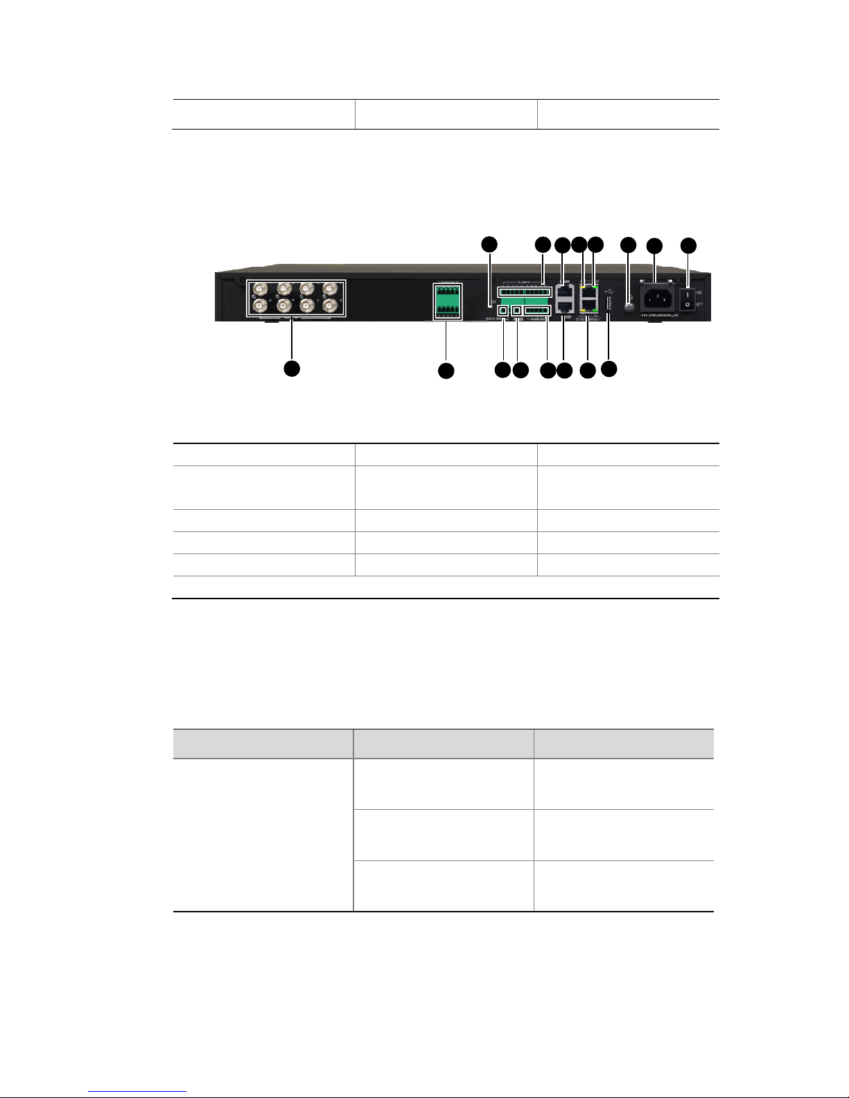
PortsandButtons.........................................................................................3
LocalCacheFunction....................................................................................6
2DeviceInstallation.................................................................................8
Precautions...................................................................................................8
InstallationFlow............................................................................................8
InstallingtheDVS4016‐INinaRack..............................................................9
PreparingfortheInstallation..............................................................10
InstallingtheMountingBrackets........................................................10
InstallingtheDVS4016‐INtotheRack................................................11
VerifyingInstallation...........................................................................11
InstallingtheDVS4016‐INonaWorkbench................................................12
PreparingfortheInstallation..............................................................12
InstallationProcedure........................................................................13
ConnectingCables.......................................................................................13
CablingRequirements.........................................................................13
ConnectingCablestoPortsontheRearPanel...................................14
ConnectingtheGroundWire..............................................................15
ConnectingtheAudioCables..............................................................17
AlarmCableConnection.....................................................................18
ConnectingtheACPowerCable.........................................................20
ConnectingthePTZ.............................................................................21
ConnectingaThird‐PartyDevice........................................................21
RS‐232SerialCableConnection..........................................................21

ii
VerifyingInstallation...................................................................................21
StartingUptheDVS4016‐IN........................................................................22
3LoggingIntoandLoggingOutoftheDVS4016‐IN.................................22
4TechnicalSpecifications.......................................................................23

1
1Overview
NOTE!
ThisdocumentpresentsthehardwareinformationoftheDVS4016‐IN,
howtoinstallit,andhowtoquicklyconfigureitthroughtheweb
interface.
Asnew‐generationnetworkvideosurveillancemediaterminals,
DVS4016‐INencoder(hereinafterreferredtoastheDVS4016‐IN)integrate
audio/videoencodingandcompressionanddatatransmission.Theyare
applicabletomonitoringandlisteningtoremotesitesinrealtime,andcan
bewidelyappliedtoreal‐timesurveillanceapplicationsinsecurity
protection,transportationmonitoring,financialinstitutions,electricity
industry,andmedicalinstitutions.
Formoreinformationaboutitstechnicalspecifications,seeTable4‐1.
Appearance
TheDVS4016‐INappearancedescribedinthismanualisforreferenceonly.
Figure1‐1Frontview
(2)
(
3
)
(1)

2
1:RunningLED2:AlarmLED3:EncodingLED
Figure1‐2Rearview
)
(6) (8)
(9)(10) (15) (16)
(11) (13)
(14)
(12)
(2) (4)
(3)
(5)
1:Videoinport2:Audioinport3:Resetbutton
4:Audiooutport5:RS‐485port
)(Phoenixcontact
6:Alarminport
7:Alarmoutport8:RS‐485port(RJ‐45)9:ActiveLED
10:LinkLED11:RS‐232port12:Ethernetport
13:USBport14:Groundingscrew15:ACpowerinput
16:Powerswitch
LEDs
Table1‐1nsLEDdescriptio
LEDStateMeaning
RUN
BlinkingdeviceisstartingThe
up.
OnisThedevice
operatingnormally.
OffdeviceispoweredThe
off.
(
1
(
7
)
45711 12 13
2
368910 14 15 16
1

3
LEDStateMeaning
ALM
Onrexample,
la
Atleastonedevice
alarm(fo
temperaturea rm)is
present.
Offis
t.
Nodevicealarm
presen
ENC
Onyare
Thereareinput
signalsbutthe
notbeingencoded.
Blinking
areinput
lsaya
There
signa ndthe re
beingencoded.
OffinputThereareno
signals.
ACT
Blinking
ce
or
Thedevi is
transmitting
receivingtraffic.
Off
Thedeviceis
transmitting
not
or
receivingtraffic.
LINK
OnAlinkispresent.
OffNolinkispresent.
Portsan s
Table1‐2Portsandbuttondescriptio
dButton
ns
Port/buttonQuantityDescriptionRemarks

4
Port/buttonQuantityDescriptionRemarks
VIDEOIN16
Analog
composit
videoinput
(PAL/NTSC),
BNCport
eReceivesanalog
s
ca
s
75ohm,1V
(P‐P)
videoignals
frommeras
andDVD
AUDIOIN16
Phoenix
contact,single
channel,35
(P‐P),
n,
kohm,2V
Formore
informatio
seeFigure2‐7
Inputsaudio
signals
AUDIOOUT2
Phoenix
contact,single
channel.10
kohm,2V(P‐P),
Formore
information,
seeFigure2‐7
Outpu saudio
signals
Note:Currently,
thedevice
supportsone
t
audiointercom
l.
lin
com
andtheaudio
inputlineshare
thesameport.
channe The
inputeof
audiointer
ALARMIN8
e
Phoenixcontact
Formor
information
seeTable2‐2
Booleaninput
Inputsalarm
signals

5
Port/buttonQuantityDescriptionRemarks
ALARMOUT2
Phoenixcontact
information
T
Formore
see able2‐2
Relayoutput
Outputsalarm
signals
RS‐4852
RJ‐45
contact
Provides
interactive
device,for
example,PTZ
cameras
connector,
Phoenix
controlwiththe
connected
RS‐2321RJ‐45co
Commissions
nnector andmaintains
thedevice
Ethernetport2
10Mbps/10
Mbps/1000
Mbps
auto‐negotiat
n
Halfdup
duplex
auto‐negotiat
RJ‐45connector
0
io
nnectsto
lex/full
io
Co an
Ethernet
n

6
Port/buttonQuantityDescriptionRemarks
RST1Resetbutton
re
less
econd
eboo
upress
thebutton
formore
thanthree
secondsand
ult
atio
•Ifyoup ss
thebutton
for than
three
s s,
thedevice
r ts.
zIfyo
andhold
thenrelease
it,the
devicewill
rebootand
restorethe
factory‐defa
configur
n
USB1
forlocal
buffering
USB2.0
storagedevice
Formore
information,
see"Local
Connectsto
Cache
Function".
LocalCacheFunction
zThedevicesupportsonlyoneUSBstoragedevice.Fordetailsabout
recommendedUSBmodels,contactrelevantsalesortechnical

7
tpersonnel.IfyouuseaUSBmobilediskrequiring
n
r
e
Ifthelocalcachefunctionisused,cachingdataatahighbitrateis
notrecommended.Inaddition,thecachewritingratemustbe
psifthemaximumwritingrateo
suppor
independentpowersupply,youneedtopreparethepowersupplyo
yourown.
zThecapacityoftheUSBstoragedevicemustbeatleast4GB.
zTheUSBportofthestoragedevicemustbeofUSB2.0orlate
versions.
zThefilesystemoftheUSBstoragedeviceusesFAT32andcanhav
onlyonepartition.
CAUTION!
z
lowerthanthemaximumwritingrateoftheUSBstoragedeviceto
avoidcacheerrors.Forexample,thebitrateconfiguredonthe
devicemustbelowerthan5Mb
f
theUSBstoragedeviceis5Mbps.
by
zHotpluggingisnotrecommendedafteryouinsertaUSBstorage
deviceintothedevice.IfyoupullouttheUSBstoragedevice
accident,youneedtorestartthedevice;otherwise,thecache
functionwillfail.
zDonotmanuallydeleteanyvideofileorfolderstoredintheUSB
storagedevice,ormanuallycopyanyfiletotheUSBstoragedevice.
Ifyouneedtousethelocalcachefunction,ensurethattheUSBstorage
eenformatted,becausetheterminaldevice
tting.
inserttheUSBdevice,thelocalcachefunctionwillautomatically
llowingacentralstoragefailure.
files
ack
erver.
devicetobeinsertedhasb
doesnotsupportUSBforma
Afteryou
startabout15secondslaterfo
Cachedfileswillbeperiodicallyoverwritten.Therefore,exportcached
intimeusingtheFTPclientorstarttheimageuploadingfunctiontob
upcachedvideosthroughabackupservermanagedbythecentrals

8
heexportedorbackedupvideofilescanbeplayedonthewebpageof
erver.
2D
T
thecentrals
eviceInstallation
Prec
CheckingDeviceComponents
outcarefully.Checkitems
enthe
elocalagentofourcompanyforhelp.Otherwise,we
foranyconsequencecausedthereby.
autions
Unpackthecontainerandremovetheitems
againstthepackinglistandensureallitemslistedareincludedinthe
container.
Donotremovethedismantlement‐preventivesealfromthechassis
coverofanDVS4016‐INwithoutpermission.Ifyouwanttoop
WARNING!
chassis,contactth
shallnotbeheldliable
heckingtheInsCtallationEnvironment
Thedevicecanbeinstalledindoorsonly,andmustmeetlightning
protectionandgroundingrequirements.
zEnsurethatappropriatelightningprotectionfacilitiesarechosenfor
devicepowersupply,audioandvideosignals,andtheRS‐485port.
zEnsurethatthedeviceiscorrectlygroundedthroughagrounding
screw.Fordetails,refertoDVS/DCCableConnectionGuide.
InstallationFlow
BeforeinstallingtheDVS4016‐IN,makesureitisdisconnectedfromthe
powersource.

9
Figure2‐1Installationflow
InstallingtheDVS4016‐INinaRack
YoucaninstallyourDVS4016‐INintoastandard19‐inchrackinoneofthe
followingtwomodes:
zForwardinstallationofmountingbrackets:Mountingbracketsare
installedinthefirsthalfofdeviceflanks.

10
zBackwardinstallationofmountingbrackets:Mountingbracketsare
installedinthesecondhalfofdeviceflanks.
InstallingtheDVS4016‐INinarackdoesnotrequireslidingrailsoratray.
ThemountingbracketsareabletobeartheweightoftheDVS4016‐IN.
Thefollowingsectionsdescribehowtofront‐mounttheDVS4016‐INina
rackwiththemountingbrackets.Theotherinstallationontherearsideis
similarandisthusomitted.
PreparingfortheInstallation
zCheckthegroundingandstabilityoftherack,determinetheposition
intherackthattheDVS4016‐INistobeinstalledto,andmakesure
thereisnoobstacleinsideorneartherackwhichmayhamperthe
installation.
zMovetheDVS4016‐INtoaplaceneartherack.
InstallingtheMountingBrackets
Confirmationbeforeinstallation
ChecktheaccessorykitshippedwiththeDVS4016‐INfortwochassis
mountingbracketsandtheirscrews.Thetwobracketsareidentical.
Installationprocedure
1. Locatethemountingholesintheleftfrontsideofthechassis.Align
thetwo‐holeflangeofamountingbracketwiththemountingholes
inthechassisside.
2. FastenthebracketontothechassiswithtwoM4×8screws,asshown
inFigure2‐2.
3. Repeattheprecedingstepstoattachtheothermountingbracketto
therightfrontsideofthechassis.

11
Figure2‐2Installthemountingbrackets
1:Screws(four)
2:Bracket
3:Screwhole
4:Waist‐shaped
hole
InstallingtheDVS4016‐INtotheRack
LifttheDVS4016‐INhorizontallytoanappropriatepositionintherack.Fix
thetwomountingbracketsontheDVS4016‐INtotherackposts,asshown
inFigure2‐3.
Figure2‐3InstalltheDVS4016‐INtotherack
VerifyingInstallation
AfterinstallingtheDVS4016‐INtotherack,checktheinstallationagainst
thefollowingchecklist.Ensurethatallcheckresultsarepositive.

12
Table2‐1Verificationitemsafterinstallation
ItemResult
Remark
No.DescriptionYesNo
1
Themounting
bracketsare
fixedtothe
DVS4016‐IN
tightly.
2
TheDVS4016‐IN
isinstalledatan
appropriate
positioninthe
rack.
3
Themounting
bracketsare
fixedtothe
mountangles
tightly.
InstallingtheDVS4016‐INonaWorkbench
Ifyoudonothaveastandard19‐inchrack,youcaninstallyour
DVS4016‐INonaworkbench.
PreparingfortheInstallation
zMakesuretheworkbenchissturdyenoughtoholdtheDVS4016‐IN,
itsaccessoriesandthecables.
zMakesuretheworkbenchiswellgroundedandisstable.
zTheDVS4016‐INisshippedwithfeet.Youneedtoremovethe
stickersfromthefeetandfastenthefeettotherightpositionsonthe
bottomoftheDVS4016‐IN.
Table of contents