BFW Long Island Technology Group BayPort User manual

6-Bay Charger
Operating Manual
BayPortTM


Table of Content
Symbol Description .....................................................................................2
Warnings and Cautions................................................................................3
Warnings and Cautions................................................................................4
Intended Use ............................................................................................................... 4
Unintended Uses ......................................................................................................... 4
Overview.....................................................................................................5
System Description ...................................................................................................... 5
Operation....................................................................................................6
Charging Batteries ....................................................................................................... 6
Cleaning and Maintenance ..........................................................................7
Charging Unit............................................................................................................... 7
Specifications ..............................................................................................8
Electromagnetic Compatibility.....................................................................9
Troubleshooting and Service .....................................................................13

2
Symbol Description
These important symbols may appear on your Long Island Technology GroupTM BayPortTM 6-Bay Charger. Please
note their meaning.
CE marking of conformity indicates this device complies with European Directive 93/42 EC
on medical devices and Directive 2002/95/EC on the restriction of the use of certain hazard-
ous substances in electrical and electronic equipment.
The UL mark indicates this product has been tested to, and conforms to applicable stan-
dards.
More information for this product can be found in this operating manual.
AS TO ELECTRICAL SHOCK, FIRE AND MECHANICAL HAZARDS ONLY
IEC 60601-1 Edition 3.1, IEC 60601-1-2 Edition 4,
ANSI/AAMI E-S60601-1 (2005), CAN/CSA-C22.2 No. 60601-1 (2008)

3
Warnings and Cautions
Users of this product should be thoroughly trained in the appropriate medical procedures. Also they should
read and understand this owner’s manual for this product and all equipment used with it. No other training is
required to use this device.
!Read and understand the Operang Manual before using the unit.
!Use BayPortTM 6-Bay Charger only with BFWTM/Long Island Technology GroupTM baeries.
!DO NOT subject the BayPortTM 6-Bay Charger to strong shocks, which include but are not limited to
dropping the unit on the oor.
!DO NOT use this unit for anything other than its intended use.
!DO NOT modify this equipment.
!DO NOT open unit. No serviceable components are inside device.
!DO NOT submerge this device or any of its components in liquid.
!WARNING Use of this equipment adjacent to or stacked with other equipment should be avoided
because it could result in improper operaon. If such use is necessary, this equipment and the other
equipment should be observed to verify that they are operang normally.
!USE ONLY components and accessories listed on page 5 and 7 of this manual. Failure to do so may de-
crease system performance, may lead to unsafe operaon, may negavely aect EMC performance and
could result in non-compliance and could void the warranty
!DO NOT use if packaging is damaged.
!WARNING Portable RF communicaons equipment (including peripherals such as antenna cables and
external antennas) should be used no closer than 30 cm (12 inches) to any part of the BayPortTM 6-Bay
Charger, including cables specied by the manufacturer. Otherwise, degradaon of the performance of
this equipment could result.
!Medical Electrical Equipment needs special precauons regarding EMC and needs to be installed and
put in service according to the EMC informaon in the Electromagnec Capability of this manual.
!WARNING Falling Hazard: avoid sing or standing under the unit when it is mounted.

4
Warnings and Cautions
!DO NOT use non-VESA mounts.
!Follow local disposal rules for electronic equipment.
!WARNING: To avoid the risk of electric shock, this equipment must only be connected to a supply main
with protecve earth
Intended Use
The BFWTM BayPortTM 6-Bay Charger is intended to only charge BFWTM/LITGTM batteries used in BFWTM/
LITGTM products. The charger is intended to be VESA compatible. The product is intended to be used by medical
professionals.

5
Overview
System Descripon
The BFWTM BayPortTM 6-Bay Charger is constructed of a durable metal housing. Six charging slots allow
up to six BFWTM/LITGTM 3 or 4 cell batteries to be charged simultaneously and stored easily. LEDs indicate the
charging status of each battery. The principle of operation is charging smart batteries.
The intended environment for use is for Professional Health Care except for near active HF Surgical Equipment
and the RF shielded room of an ME System for magnetic resonance imaging.
C
D
A
B
A. BFWTM BayPortTM 6-Bay Charger
B. AC Cable
C. 4-Cell Battery
D. 3-Cell Battery

6
Operation
Charging Baeries
1. Plug the female end of the AC Cable (B) into the AC Power Receptacle (C) on the bottom of the unit.
2. Plug the male end of the AC Cable (B) in an AC Outlet.
3. Flip the main power switch into the On position on the AC Power Receptacle (C).
4. Fully charging the Battery before use, will ensure the longest Battery life.
A
B
C
A. Charging Indicators (See Table Below)*
B. AC Cable
C. AC Power Receptacle
Charging Indicator*
Green Blinking Battery is currently being charged
Green Solid Battery is fully charged
Red Blinking An error has occurred during charing
5. Flip the main power switch into the OFF position on the AC Power Receptacle (C) to turn the unit off.
!The appliance inlet shall not be blocked during operaon. This will make it dicult to disconnect the
device

7
Cleaning and Maintenance
Charging Unit
1. Clean the BayPortTM 6-Bay Charger components with an alcohol wipe.
2. Use a can of compressed air to clean out any dust accumulations.
!DO NOT pour cleaning soluon directly on the surface of the BayPortTM 6-Bay Charger
!DO NOT use any sterilizaon process or cleaning process using excessive heat or humidity as it will
damage the device
!NEVER immerse the unit in any type of liquid
Note: Damaging any part of the system with the use of an improper cleaning agent or cleaning process will
void all warranties.

8
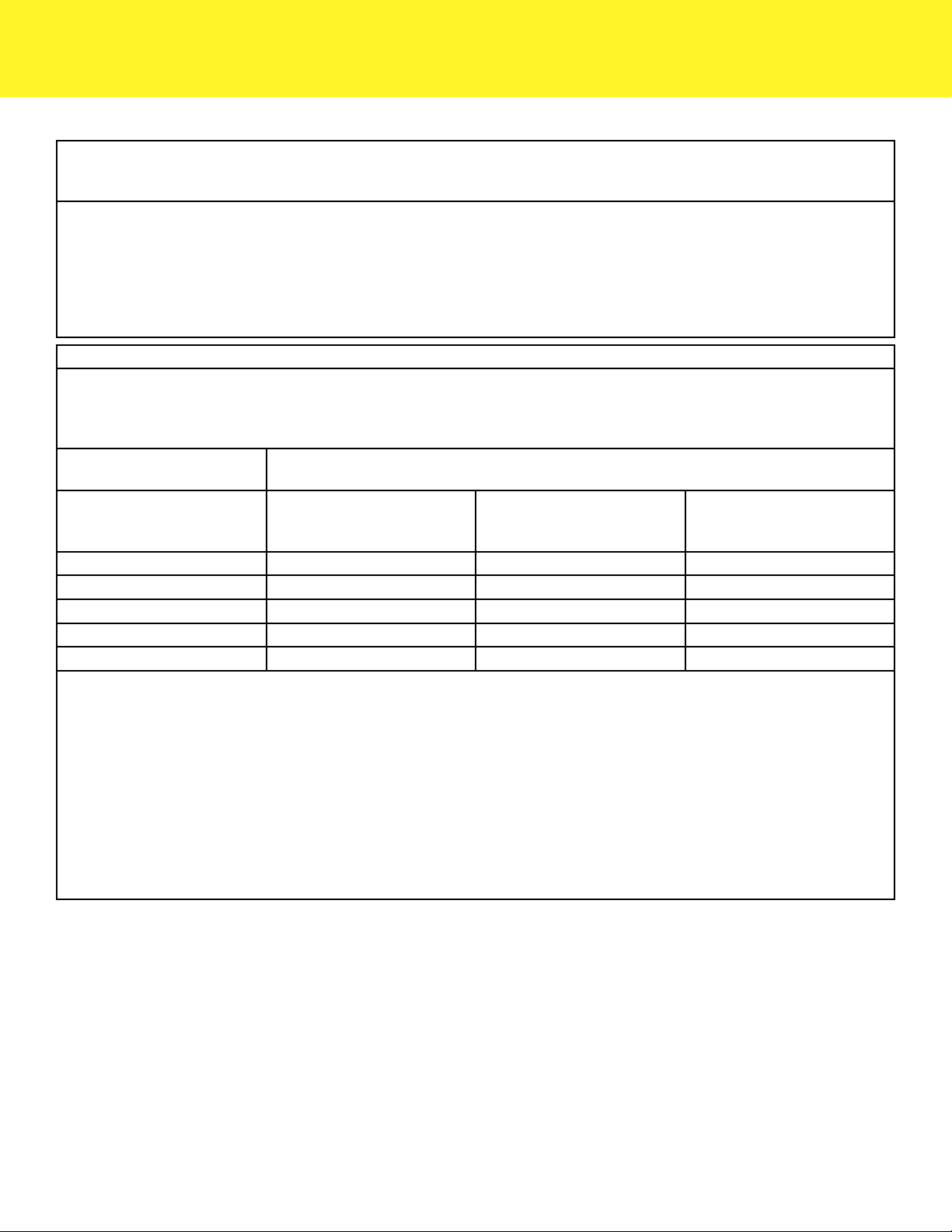
Specications
Classification
Classification & Type None
Environment
Operation 60 Degrees F (15 C) to 80 Degrees F (26.7 C)
Storage 23 Degrees F (0 C) to 104 Degrees F (40 C)
Relative Humidity 45% - 75%
Pressure/Altitude 860 - 1,060 hPa/2,000m
Performance
Charge Time from Empty ~3 hours
Mechanical
LxWxH 19.25” x 8.125” x 2.5”
Weight 11.7 lbs
Electrical
Input Voltage 100-240 VAC 50/60 Hz
Input Current 1.0 A Max
Line Cord (IEC 60320) Maximum Length 10ft

9
Electromagnetic Compatibility
Portable and mobile RF communications equipment can affect medical electrical equipment
Guidance and manufacturer’s declaration-electromagnetic emissions
e BayPortTM 6-Bay Charger is intended for use in the electromagnetic environment specied below. e customer or the user of the
BayPortTM 6-Bay Charger should assure that it is used in such an environment
Immunity
Test
IEC 60601 Test
Level Compliance Level Electromagnetic Environment Guidance
Conducted
RF IEC
61000-4-6
Radiated
RF IEC
61000-4-3
3 Vrms 150kHz - 80
MHz
3V/meter 80 MHz -
2.5 GHz
3 Vrms
3V/m from
30MHz to 1GHz,
3V/m for 1 GHz to
25GHz; (1000 Hz
80% Modulated
Test Signal)
Portable and mobile RF communications equipment should be used no
closer to any part of the BayPortTM 6-Bay Charger, including cables, than
the recommended separation distance calculated from the equation appli-
cation to the frequency of the transmitter.
Recommended Separation Distance:
Battery Operated Device
d = 1.17√P
d = 1.17√P 80 MHz to 800 MHz
d = 2.23√P 800 MHz to 2.5 GHz
Where P is the maximum output power rating of the transmitter in
watts(W) according to the transmitter manufacturer and d is the recom-
mended separation distance in meters (m).
Field strengths from xed RF transmitters, as determined by an electro-
magnetic site survey (1), should be less than the compliance level in each
frequency range (2).
Interference may occur in the vicinity of equipment marked with the
following symbol:
10
Electromagnetic Compatibility
NOTE 1: At 80 MHz, the separation distance for the higher frequency range applies.
NOTE 2: ese guidelines may not apply in all situations. Electromagnetic propagation is aected by absorption and reection from
surfaces, objects, and people.
(1) Field strengths from xed transmitters, such as base stations for radio (cellular/cordless) telephones and land mobile radios, am-
ateur radio, AM and FM radio broadcast and TV broadcast cannot be predicted theoretically with accuracy to asses the electromag-
netic environment due to xed RF transmitters, an electromagnetic site survey should be considered. If the measured eld strength
in the location in which the BayPortTM 6-Bay Charger is used exceeds the applicable RF compliance level above, the BayPortTM 6-Bay
Charger should be observed to verify normal operation. IF abnormal performance is observed, additional measure may be necessary,
such as re-orienting or relocating the BayPortTM 6-Bay Charger.
(2) Over the frequency range 150kHz to 80MHz, eld strengths should be less than 3 V/m.
Recommended separation distances between portable and mobile RF communications equipment and the BayPortTM 6-Bay Charger
e BayPortTM 6-Bay Charger is intended for use in an electromagnetic environment in which radiated RF disturbances are con-
trolled. e customer or user of the BayPortTM 6-Bay Charger can help prevent electromagnetic interference by maintaining a
minimum distance between portable and mobile RF communications equipment (transmitters) and the BayPortTM 6-Bay Charger as
recommended below, according to the maximum output power of the communications equipment.
Rate maximum output power
of transmitter
Separation distance according to frequency of transmitter in meters
W 150 kHz to 80 MHz
d = 1.17 P
80 MHz to 800 MHz
d = 1.17 P
800 MHz to 2.5 GHz
d = 2.23 P
.01 0.12 0.12 0.23
.1 0.37 0.37 0.737
1 1.17 1.17 2.33
10 3.70 3.70 7.37
100 11.70 11.70 23.30
For transmitters rated at a maximum output power not listed above, the recommended separate distance d in meters (m) can be esti-
mated using the equation applicable to the frequency of the transmitter, where P is the maximum output power rating of the trans-
mitter in watts (W) according to the transmitter manufacturer.
NOTE 1: At 80 MHz and 800 MHz, the separation distance for the higher frequency range applies.
NOTE 2: e ISM (industrial, scientic and medical) bands between 150 kHz and 80 MHz are 6.765 MHz to 6.795 MHz; 13.553
MHz to 13.567 MHz; 26.957 MHz to 27.283 MHz; and 40.66 MHz to 40.70 MHz.
NOTE 3: An additional factor of 10/3 has been incorporated into the formulae used in calculated the recommended separation dis-
tance for transmitters in the ISM frequency bands between 150 kHz and 80 MHz and in the frequency range 80 MHz to 2.5 GHz to
decrease the likelihood that mobile/portable communications equipment could cause interference if it is inadvertently brought into
patient areas.
NOTE 4: ese guidelines may not apply in all situations. Electromagnetic propagation is aected by absorption and reection from
surfaces, objects, and people.

11
Electromagnetic Compatibility
Guidance and manufacturer’s declaration - electromagnetic immunity
e BayPortTM 6-Bay Charger is intended for use in the electromagnetic environment specied below. e customer or the end user
of the BayPortTM 6-Bay Charger should assure that it is used in such an environment.
Immunity test IEC 60601 test level Compliance level Electromagnetic environment - guidance
Electrostatic dis-
charge (ESD)
IEC 61000-4-2
± 8 kV contact
± 2 kV, ± 4 kV, ± 8 kV, ± 15
kV air
IEC 61000-4-2
± 8 kV contact
± 2 kV, ± 4 kV, ± 8 kV, ± 15
kV air
Floors should be wood, concrete or ceramic
tile. If oors are covered with synthetic mate-
rial, the relative humidity should be at least 30
%. e user of the (BayPortTM 6-Bay Charger)
should avoid situations that could result in
excess electrostatic discharge.
Radiated RF electro-
magnetic eld
IEC 61000-4-3
3 V/m
80 % AM at 1 kHz
IEC 61000-4-3
3 V/m
80 % AM at 1 kHz
Radiated RF levels should be that of a typical
commercial or hospital environment
Proximity elds
from RF wireless
communications
equipment
IEC 61000-4-3
See Table 9 on page 22.
IEC 61000-4-3
See Table 9 on page 22.
RF wireless communications equipment
should be used no closer than 30 cm to the
BayPortTM 6-Bay Charger.
Electrical Fast Tran-
sient/burst
IEC 61000-4-4
± 2 kV for power supply lines
100kHz repetition frequency
IEC 61000-4-4
± 2 kV for power supply lines
100kHz repetition frequency
Mains power quality should be that of a typi-
cal commercial or hospital environment.
Surge
IEC 61000-4-5
± 0,5 kV, ± 1 kV line(s) to
line(s)
± 0,5 kV, ± 1 kV, ± 2 kV
line(s) to earth
IEC 61000-4-5
± 0,5 kV, ± 1 kV line(s) to
line(s)
± 0,5 kV, ± 1 kV, ± 2 kV
line(s) to earth
Mains power quality should be that of a typi-
cal commercial or hospital environment.
Conducted Distur-
bances induced by
RF elds
IEC 61000-4-6
3 V
0,15 MHz - 80MHz
6 V in ISM bands between
0,15 MHz and 80 MHz
80% AM at 1 kHz
IEC 61000-4-6
3 V
0,15 MHz - 80MHz
6 V in ISM bands between
0,15 MHz and 80 MHz
80% AM at 1 kHz
Mains power quality should be that of a typi-
cal commercial or hospital environment.
Voltage dips, short
interruptions and
voltage variations on
power supply input
lines
IEC 61000-4-11
0 % UT; 0,5 cycle
At 0°, 45°, 90°, 135°, 180°,
225°, 270° and 315°
0 % UT; 1 cycle
and
70 % UT; 25/30 cycles
Single phase: at 0°
0 % UT; 250/300 cycle
IEC 61000-4-11
0 % UT; 0,5 cycle
At 0°, 45°, 90°, 135°, 180°,
225°, 270° and 315°
0 % UT; 1 cycle
and
70 % UT; 25/30 cycles
Single phase: at 0°
0 % UT; 250/300 cycle
Mains power quality should be that of a typi-
cal commercial or hospital environment.
If the user of the BayPortTM 6-Bay Charger
requires continued operation during power
mains interruptions, it is recommended that
the BayPortTM 6-Bay Charger be powered
from an uninterruptible power supply or a
battery.
NOTE UT is the a.c. mains voltage prior to application of the test level.

12
Electromagnetic Compatibility
Guidance and manufacturer’s declaration - Electromagnetic Emissions
e BayPortTM 6-Bay Charger is intended for use in the electromagnetic environment specied below. e customer or the end user
of the BayPortTM 6-Bay Charger should assure that it is used in such an environment.
Emissions Test IEC 60601 test level Compliance level Electromagnetic environment - guidance
RF emissions
CISPR 11
Group 1 Group 1
e BayPortTM 6-Bay Charger uses RF energy
only for its internal function. erefore, its
RF emissions are very low and are not likely
to cause any interference in nearby electronic
equipment.
RF emissions
CISPR 11 Class A Class A
e BayPortTM 6-Bay Charger is suitable for use
in all establishments other than domestic and
those directly connected to the public low-volt-
age power supply network that supplies build-
ings used for domestic purposes.
Harmonic emissions
IEC 61000-3-2
Class A Class A
Voltage uctuations/
icker emissions
IEC 61000-3-3
Complies Complies
NOTE e EMISSIONS characteristics of this equipment make it suitable for use in industrial areas and hospitals (CISPR 11 class
A). If it is used in a residential environment (for which CISPR 11 class B is normally required) this equipment might not oer adequate
protection to radio-frequency communication services. e user might need to take mitigation measures, such as relocating or re-ori-
enting the equipment.
Table 9 - Test specications for Enclosure Port Immunity to RF wireless communications equipment
Test frequency
(MHz)
Band (MHz) Service Modulation Maximum power
(W)
Distance (m) Immunity Test
Level (V/m)
385 380 - 390 TETRA 400 Pulse modulation
18Hz 1,8 0,3 27
450 430 - 470 GMRS 460,
FRS 460
FM
± 5Hz deviation
1 kHz sine
2 0,3 28
710
704 - 787 LTE Band 13, 17 Pulse modulation
217 Hz 0,2 0,3 9745
780
810
800 - 960
GSM 800/900,
TETRA 800,
iDEN 820,
CDMA 850,
LTE Band 5
Pulse modulation
18Hz 2 0,3 28
870
930
1720
1700 - 1990
GSM 1800;
CDMA 1900;
GSM 1900;
DECT;
LTE Band 1, 3,
4, 25; UMTS
Pulse modulation
217 Hz 2 0,3 28
1845
1970
2450 2400 - 2570
Bluetooth,
WLAN,
802.11 b/g/n,
RFID 2450,
LTE Band 7
Pulse modulation
217 Hz 2 0,3 28
5240
5100 - 5800 WLAN 802.11 a/n Pulse modulation
217 Hz 0,2 0,3 95500
5785
13
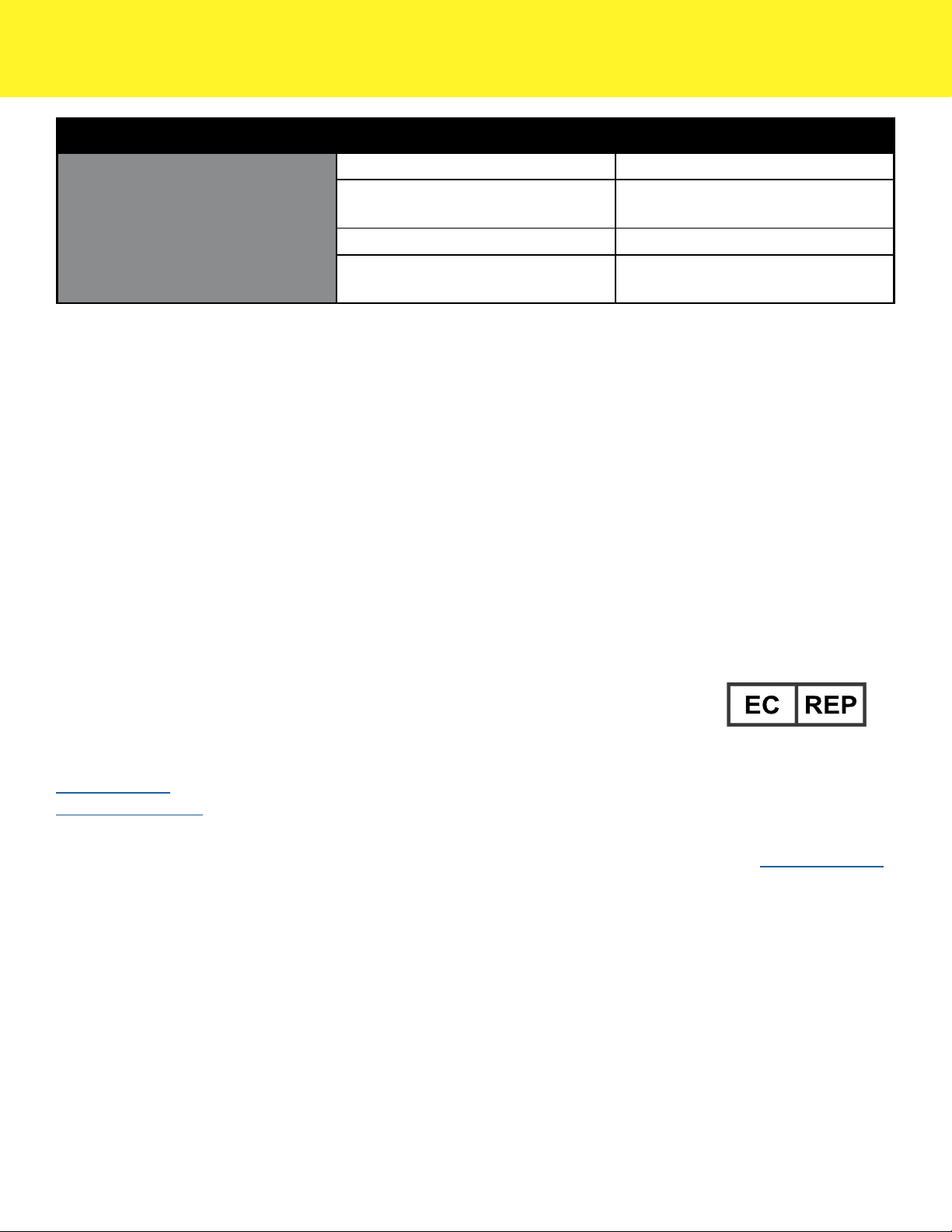
Troubleshooting and Service
Symptom Possible Issue Soluon
Battery(ies) not charging
Main power cord not plugged in Plug in cord
Main power switch is not fully
engaged Toggle ON/OFF switch
Bad battery(ies) Replace battery(ies)
Internal component failure Return unit to manufacturer for
service
Warranty and Service
Warranty against manufacturer’s defects applies to the following components of the BayPort™ 6-Bay Charger
under normal use for one (1) year from the date of sale from Long Island Technology Group (includes parts and
labor).
The warranty does not cover products damaged by the following:
• Accident, misuse, abuse, or alteration
• Servicing by unauthorized persons
• Use with unauthorized accessories
In all cases Long Island Technology Group, reserves the right to determine the cause of all malfunctions and at
its sole discretion will determine the damage and/or repairs that are covered under this warranty.
Send All Inquires To:
Long Island Technology Group, LLC
60 Carolyn Blvd
Farmingdale, New York 11735
USA
www.litgp.com
Tel: (631)-270-4463
Fax: (631)-414-7078
Obelis s.a.
Blvd Géné ral Wahis 53
1030 Brussels, Belgium
Tel: +(32) 2.732.59.54
Fax: +(32)2.732.60.03
Email: [email protected]
14
60 Carolyn Blvd, Farmingdale NY 11735
(631) 270-4463 litgp.com
Scan Here to See All Long
Island Technology GroupTM
Manuals
Or Visit: http://www.litgp.com/manuals
Revision 1.1 9/30/2019
Contents are fragile.
Handle with care.
Conforms to:
IEC 60601-1 Edition 3.1, IEC 60601-1-2 Edition 4
AAMI ES60601-1 Edition 1, CSA C22.2 NO 60601-1:08 Edition 2
Manufactured by Long Island Technology Group, LLC
60 Carolyn Blvd, Farmingdale, NY 11735
Table of contents


 manual")


