BGB Leak Detector User manual

Electronic
Leak Detector
(cat.# 33333)
Instruction Manual
www.bgb-info.com

Table of Contents Page
1.0 Introduction.......................................................................... 3
2.0 Battery Charging .................................................................. 3
3.0 Powering Up.......................................................................... 4
4.0 Zeroing the Unit................................................................... 4
5.0 Prior to Operation................................................................ 4
6.0 Detecting Leaks.................................................................... 5
7.0 Specifications ....................................................................... 5
8.0 Maintenance ......................................................................... 6
9.0 Troubleshooting ................................................................... 6
10.0 Technology ........................................................................... 7
11.0 Interpretation of Results..................................................... 8
12.0 Back Label Explanation ....................................................... 9
13.0 Case Specifications .............................................................. 10
14.0 Service.................................................................................... 10
© 2015 BGB. All rights reserved.
The BGB logo and design are registered trademarks of BGB

www.bgb-info.com
- 3 -
Operating Instructions
1.0 Introduction
BGB’s portable leak detector is specifically designed for use with gas chromatography (GC) systems. It detects minute leaks of any gas with a ther-
mal conductivity different from air. The reference gas inlet (Figure 1) draws in ambient air for comparison to air drawn into the sample probe. The
severity of a leak is indicated by both an LED light display and an audible alarm.
If this instrument is used in any manner other than described in the manual, the CE and Ex declaration is void.
2.0 Battery Charging
The leak detector should be fully charged prior to use. Only use the AC adaptor provided. To charge the battery, first install the correct plug for your
country’s AC outlets onto the provided AC adaptor. Insert the AC adaptor into an electrical outlet, and then insert the barrel plug on the other end of
the AC adaptor into the connector on the bottom of the leak detector unit. The green battery charge indicator LED will illuminate. When the battery
is fully charged, the green battery charge indicator LED will go out. When the leak detector’s charge is low, the BLUE LED located between the red
and yellow LEDs will begin to flash.
If unit is off, the BLUE LED may flash when the power button is depressed. If the battery is fully discharged, no LED will illuminate.
CAUTION: DO NOT charge the leak detector in a hazardous location.
NOTE: Replacement of the rechargeable battery in this unit is performed at the factory. There are no serviceable parts in this unit.
Opening the case or tampering with the internal parts will void the factory warranty.
NOTE: Recharging a fully discharged battery will take 3–5 hours.
NOTE: If the battery is fully discharged and you need to use the leak detector, charge the battery for 15 minutes, and then disconnect the
unit from the AC adaptor. You will be able to use it for approximately 30 minutes. After use, fully charge the battery.

- 4 -
www.bgb-info.com
3.0 Powering Up
Depress and hold the power button (Figure 1) until the unit responds
with the wake-up mode. The leak detector will run through a self-
calibration sequence for approximately 15 seconds. During this time
DO NOT attempt to zero the unit.
4.0 Zeroing the Unit
After the LED lights stop flashing, the unit is ready for use. The instrument
may need to be zeroed periodically between uses, especially if it is moved
from room to room or between areas of differing temperature or humidity.
Do not attempt to zero the unit while the probe is stored in the holder. The
probe MUST be removed from the probe docking station before zeroing the
unit. To re-zero, press the zero set button. The unit will run a self-calibration
sequence for approximately 4 seconds. When all LED lights stop flashing
and the blue LED light is lit, the unit is ready for use.
NOTE: To avoid false readings, do not attempt to use or zero the unit while the self-calibration sequence is in progress.
5.0 Prior to Operation
Verify the operation of the leak detector before each use by sampling gas from a GC split vent or other source of hydrogen or helium. Also,
visually inspect the probe tip, reference gas inlet, and exhaust port for obstructions (Figure 1).
IMPORTANT: Fittings being checked must be clean and dry; liquid leak detecting agents, dust, and other debris may damage the leak detector if
drawn into the probe.
The leak detector responds to almost any gas you can smell and many gases that you can’t smell. Solvent vapors, split vent exhaust, or even
strong air currents around the probe or reference inlet can cause instability or false positive readings. Be careful not to breathe into the refer-
ence inlet when checking for leaks or to cover/block the inlet with your hand.
Figure 1: Leak detector schematic.

www.bgb-info.com
- 5 -
6.0 Detecting Leaks
Slowly move the probe tip around fittings and other potential leak sources. If the leak detector senses a gas other than air, the LED bar graph
will begin to light, with more lights indicating a more significant leak. On the 3rd red or 2nd yellow LED, an audible tone will begin to beep.
The more LEDs that illuminate, the faster the beep. When the last red or yellow LED illuminates, the beep becomes a steady tone. The red LED
lights indicate a helium or hydrogen leak. The yellow LED lights indicate a nitrogen, argon, or carbon dioxide leak. Remove the probe from
the vicinity of the leak and allow the unit to return to zero. If a large amount of gas has entered the probe, it may take a few seconds for the
instrument to clear itself. Do not attempt to zero the unit while it is clearing out the gas from the probe. This may cause the unit to malfunc-
tion. Place the probe near the leak again to confirm its location. The reference gas inlet (Figure 1) must not be restricted or the unit will not
operate correctly. Similarly, the exhaust port allows the gas being tested to exit the leak detector and must remain unobstructed. The exhaust
port is located in the probe docking station.
CAUTION: This unit is designed to detect TRACE AMOUNTS of hydrogen arising from a small leak in a nonflammable environment,
e.g., laboratory room air, etc. This unit is rated for use in a nonflammable atmosphere where the sample gas may become sufficiently high in
concentration to become explosive.
NOTE: To disable the audible beep during leak detection, depress and hold the zero set button for 2–3 seconds. After you hear a steady tone
for 1 second, release the button; the beep function is disabled. To turn the beep function on again, depress and hold the zero set button. The
beep function is always enabled at power up.
NOTE: The leak detector will power down after 6 minutes of operation. This feature prevents excess battery discharge if the unit is accidentally
left on.
7.0 Specifications
Power Rating: 3.7 volts DC, 60 mA (AC adaptor supplied) Warranty: 1-year warranty
Battery Rating: 12 hours normal operation Certifications: CE, Ex, and Japan
Operating Temp. Range: 32–120 °F (0–48 °C) Compliance: WEEE, RoHS
Humidity Range: 0–97%

- 6 -
www.bgb-info.com
Figure 3:
Cap removed,
exposing probe tip
brush for cleaning.
Figure 2:
Cap unscrewed
and partially
removed.
8.0 Maintenance
Avoid spilling liquids onto the unit, or it may malfunction. If a liquid is spilled onto the unit, turn
off the power immediately, remove heavy liquids with a dry towel, and let the unit sit until the liquid
dries. Dust and debris can enter the probe tip of the leak detector and, over time, can clog the small-
bore tubing inside the unit. To prevent this, clean the probe tip periodically. To clean the probe tip,
unscrew the cap to expose the brush (Figures 2 and 3). Gently clean the probe using a small brush or
your fingers to remove dust and debris, then replace the cap. Do not use liquids to clean the probe.
Liquids can damage the leak detector if drawn in through the probe.
Information on where to have the unit sent for maintenance or service* is listed at the end of this
document.
9.0 Troubleshooting
*Contact BGB for return instructions for servicing a damaged unit. Additional charges may apply if the warranty has expired or the unit is damaged due to misuse.
Problem Possible Cause Suggested Solution
Sensitivity decreased
Probe clogged Clean the probe tip to remove any debris
Probe line punctured Visually inspect probe line for holes*
Response decreased Detector not zeroed Re-zero detector
LED bar graph stays lit during operation
Detector re-zeroed before unit was purged out Allow adequate time for detector to purge, then re-zero
Reference gas inlet covered by hand or other object Remove obstruction
Does not power up Batteries need to be charged Charge unit

www.bgb-info.com
- 7 -
10.0 Technology
The leak detector measurement is based on thermal conductivity comparisons between the probe air and a reference air. The device employs
a dual thermistor technology that measures the ratio of [probe]:[reference] heat exchange values and displays the results on an LED scale
(Figure 4). Under ideal operating conditions, a ratio of 1:1 indicates identical air samples for both [probe] and [reference], and therefore, no
leak is present.
Because of slight differences in air temperature and/or humidity between the reference inlet (Figure 1) and the probe tip, a small response
indicated by a single red or yellow LED light is generally insufficient to positively identify a gas leak. Small to moderate leaks are reliably
indicated with 3 red or 2 yellow LED lights and an intermittent beep. Larger leaks are indicated with all red or yellow LED lights lit and a
continuous audible alarm.
LEFT: Dual analysis is achieved with heater
elements positioned in separate flow chambers.
RIGHT: Probe and reference air streams are
simultaneously monitored for thermal
conductivity. Differences in air composition
are indicated by differences in the heater
element currents.
Figure 4: Schematic layout of the leak detector technology.

- 8 -
www.bgb-info.com
11.0 Interpretation of Results
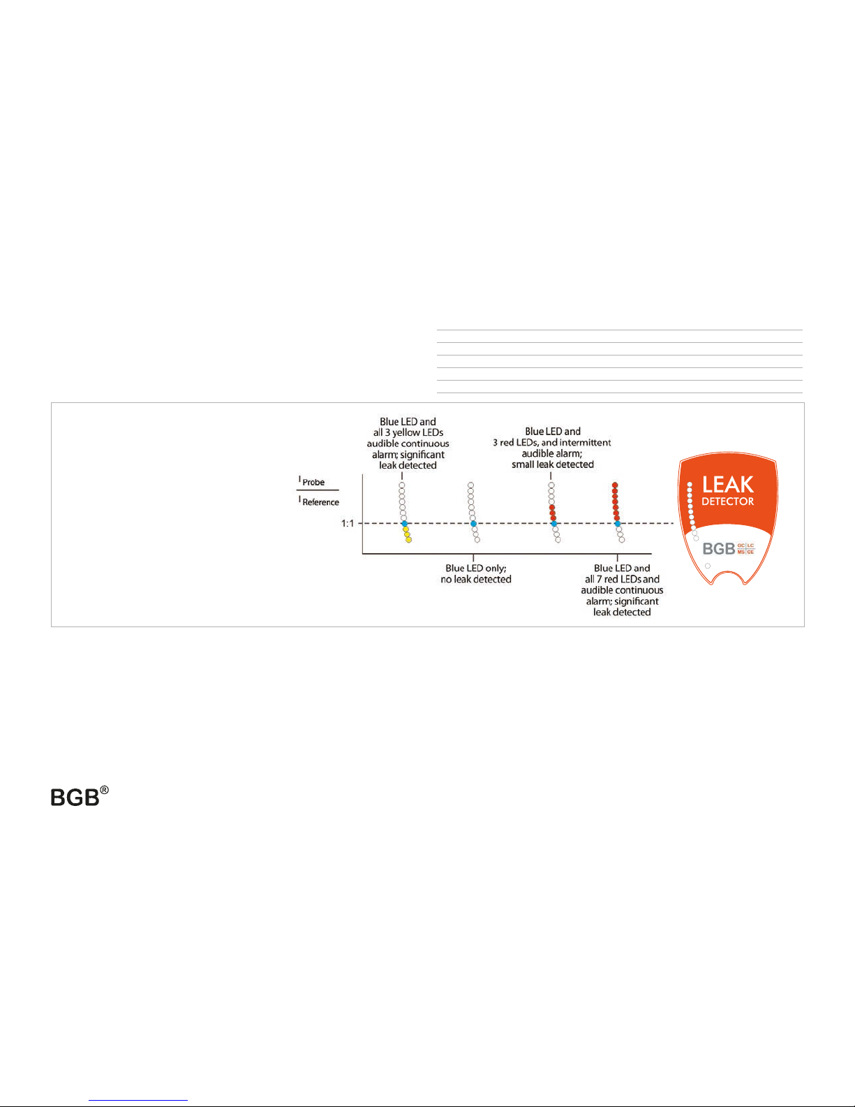
Figure 5 illustrates the leak detector’s LED light response range. The
greater the number of red or yellow LED lights lit correlates in general to
the size of the leak. NOTE: The leak detector is not a quantitative device,
rather it is designed to detect leaks in gas line connections commonly
associated with laboratory equipment.
**CAUTION: This unit is designed to detect TRACE AMOUNTS of hydrogen arising from a small leak in a nonflammable environment, e.g., laboratory room air, etc. This unit is rated for use in a
nonflammable atmosphere where the sample gas may become sufficiently high in concentration to become explosive.
Tip drift
Tip drift is the phenomenon when a false LED light response is registered as the unit is quickly turned or swept in dramatic arc movements. Tip
drift is inherent to all dual thermistor leak detector technology and is based in large part on the asymmetry of the flow cells; shaking or tipping
the unit influences the air flow profiles, which impacts the rates of heat exchange. If the device is functioning normally, the LED light signal will
return to zero in 3–5 seconds after the unit is held still. In extreme cases, the unit may require another “zero” cycle before using. To avoid tip drift,
be sure to hold the unit steady while making measurements.
Minimum Detectable Indicating
Gas Leak Rate (atm cc / sec) LED Light Color
Helium 1.0 x 10⁻⁵ Red
Hydrogen** 1.0 x 10⁻⁵ Red
Nitrogen 1.4 x 10⁻³ Yellow
Argon 1.0 x 10⁻⁴ Yellow
Carbon dioxide 1.0 x 10⁻⁴ Yellow
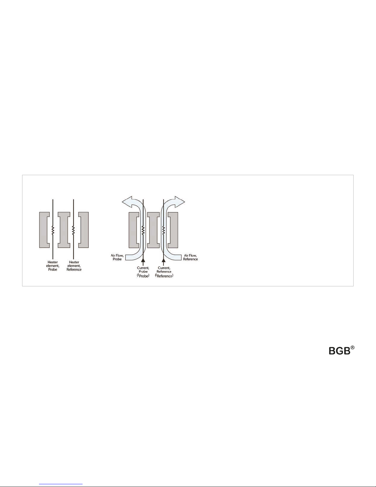
Figure 5: LED light response
chart for the leak detector. A 1:1
ratio of IProbe : IReference indicates
no leak present. Red LED lights
indicate the presence of helium
and/or hydrogen. Yellow LED
lights indicate the presence of
nitrogen, argon, and/or carbon
dioxide.
33333 110001
33333

www.bgb-info.com
- 9 -
12.0 Back Label Explanation
1. Product name.
2. Product catalog number.
3. Product serial number.
4. Warning note: This plastic case does not exhibit adequate
surface resistance properties suitable for high electric fields.
DO NOT CHARGE THIS DEVICE IN A HAZARDOUS AREA.
5. Definition of symbols—see table at right.
6. This unit conforms to EU/EMC Directive 2004/108/EC,
Standards to which Conformity is declared include
EN61326-1:2006 w/A3 Class A.
7. Unit is WEEE compliant.
8. Unit is RoHS compliant.
9. This complies with part 15 of the FCC Rules. Operation is
subject to the following 2 conditions: (1) This device may not
cause harmful interference, and (2) this device must accept any
interference received, including interference that may cause
undesired operation.
10. This Class A digital apparatus complies with Canadian ICES-003.
11. Units must be sent back to BGB for service.
12. Manufacturer company name, address, and contact information.
13. Electrical parameters.
14. ATEX coding: for definition of symbols see table to the right.
1
4
5
6
7
8
2
3
9
10
11
12
13
5
14
Definition of back label symbols.
DC Voltage
Ex nA EN60079-0: 2012; Electrical apparatus for explosive gas atmospheres- Part 0: General Requirements
EN60079-15: 2010; Electrical apparatus for explosive gas atmospheres- Part 15:
Electrical Apparatus With Type of Protection “n”
IIC Group II applies to areas above ground environments. Gas Group IIC relates to hydrogen and
related gas types.
T6 While testing this unit neither internal nor external elements exceed 85 °C.
X Additional information.
Operating range. 32 °F ≤Tamb ≤120 °F
0 °C ≤Tamb ≤48 °C
This unit is designed to detect TRACE AMOUNTS of hydrogen arising from a small leak in a
nonflammable environment, e.g., laboratory room air, etc.
This unit is rated for use in a nonflammable atmosphere where the sample gas may become
sufficiently high in concentration to become explosive.
13.0517 Certificate Reference
EU Explosive Atmosphere symbol.
11 Equipment Group (non-mining).
3 Normal protection.
G Gas.
_ _ _

- 10 -
www.bgb-info.com
13.0 Case Specifications 14.0 Service
The BGB leak detector carries a 1-year limited warranty from time
of purchase. Please have the leak detector serial number available
when calling BGB with any concerns you may have. Additional
charges may apply if the warranty is expired or the damage is due to
misuse.
Expected battery lifetime is 2 years from time of purchase. Customers
will need to return the unit to BGB for battery replacement. At that
time, preventative maintenance services can also be performed on the
unit. A fee will be charged for servicing the unit.
For questions, problems, or repair services:
BGB Analytik AG • Rohrmattstrasse 4 • CH-4461 Böckten • Phone +41 61 991 00 46 • Fax +41 61 991 00 25
BGB Analytik SA • Route de Pré-Bois 20 • CH-1215 Genève 15 • Phone +41 22 788 49 43 • Fax +41 22 788 49 45
BGB Analytik Vertrieb GmbH • Josefstrasse 19a • DE-79618 Rheinfelden • Phone +49 7623 717 31 10 • Fax +49 7623 717 31 99

© 2015 BGB. All rights reserved.
The BGB logo and design are registered trademarks of BGB
Inhaltsverzeichnis Seite
1.0 Einleitung ............................................................................ 12
2.0 Akku aufladen..................................................................... 12
3.0 Einschalten .......................................................................... 13
4.0 Nullabgleich........................................................................ 13
5.0 Vor Inbetriebnahme........................................................... 13
6.0 Lecks finden ........................................................................ 14
7.0 Spezifikationen................................................................... 14
8.0 Wartung ............................................................................... 15
9.0 Fehlersuche ......................................................................... 15
10.0 Funktionsweise .................................................................. 16
11.0 Interpretation der Anzeige............................................... 17
12.0 Erklärung des Labels auf der Rückseite ......................... 18
13.0 Spezifikationen des Gehäuses ......................................... 19
14.0 Service.................................................................................. 19
Elektronischer Leck Sucher (Best.Nr.# 33333)
Bedienungsanleitung

- 12 -
www.bgb-info.com
Bedienungsanleitung
1.0 Einleitung
Der tragbare Leak Detector von BGB wurde für die Verwendung in der Gaschromatographie (GC) entwickelt. Er detektiert sehr kleine Lecks
von jedem Gas, dass eine andere Wärmeleitfähigkeit, als die umgebende Luft, hat. Über den Referenzgas Einlass (Abbildung 1) wird Luft aus
der Umgebung zum Vergleich mit dem Gas von der Prüfspitze bezogen. Unterscheiden sich die beiden Gase, wird dies visuell durch LED’s,
sowie einem akustischen Signal angezeigt.
Sollte das Gerät zu einem anderen Zweck, als in dieser Bedienungsanleitung beschrieben, genutzt werden, verfällt das CE und Ex Zertifikat.
2.0 Akku aufladen
Der Leak Detector sollte vor Gebrauch vollständig aufgeladen werden. Verwenden Sie dazu nur das mitgelieferte Ladegerät mit dem passenden
Steckeradapter für Ihr Land. Stecken Sie zuerst das Ladegerät in die Steckdose und anschliessend das Ladekabel in die Buchse am Unterteil des Leak
Detectors. Die grüne LED leuchtet während des Ladevorgangs. Sobald diese erlischt, ist der Ladevorgang abgeschlossen. Zwischen den roten und gel-
ben LED’s liegt eine blaue LED. Blinkt diese, muss der Leak Detector geladen werden.
Beim Einschalten des Gerätes kann die blaue LED kurz aufblinken. Ist der Akku komplett entladen, leuchten keine LED’s.
Vorsicht: Laden Sie den Leak Detector nicht an einem gefährlichen Standort auf.
Bemerkung: Der Akku im Gerät darf nur vom Hersteller ersetzt werden. Es gibt keine Teile im Gerät die Wartung benötigen.
Beim Öffnen des Gerätes erlischt die Garantie.
Bemerkung: Der Ladevorgang eines völlig entladenen Akku’s kann 3-5 Stunden dauern.
Bemerkung: Sollten Sie dringend Messungen machen und der Akku ist leer, laden Sie das Gerät für 15 Minuten und nehmen Sie es
vom Netz. Sie können jetzt für etwa 30 Minuten messen. Im Anschluss sollte der Akku aber komplett geladen werden.

www.bgb-info.com
- 13 -
3.0 Einschalten
Drücken Sie die Power Taste (Abbildung 1) bis das Gerät reagiert. Der
Leak Detector startet eine interne Kalibrierung die ca. 15 Sekunden
dauert. Führen Sie in dieser Zeit keine Messung oder Nullpunkt
Einstellung durch.
4.0 Nullpunkt Einstellung
Sobald die LED’s mit dem Blinken aufhören, ist das Gerät betriebs-
bereit. Von Zeit zu Zeit muss der Nullpunkt wieder gesetzt werden.
Veränderte Raumbedingungen wie Temperatur und Luftfeuchtigkeit
haben einen Einfluss auf den Nullpunkt. Versuchen Sie niemals eine
Nullpunkt Einstellung wenn sich die Prüfspitze in der Halterung befindet.
Die Prüfspitze MUSS vor der Nullpunkt Einstellung aus der Halterung
genommen werden. Zur Nullpunkt Einstellung die „Zero“ Taste drücken.
Das Gerät führt eine interne Kalibrierung durch die ca. 4 Sekunden dauert.
Wenn alle LED’s aufhören zu blinken und die blaue LED leuchtet, ist das
Gerät zur Benutzung bereit.
Bemerkung: Um falsche Messwerte zu vermeiden, sollten Sie mit dem Gerät während der internen Kalibrierung nicht messen.
5.0 Vor der Inbetriebnahme
Überprüfen Sie die Funktion des Leak Detectors vor jedem Gebrauch durch kurzes Messen am Split Ausgang des GC’s, oder einer anderen Quelle
von Wasserstoff oder Helium. Kontrollieren Sie Prüfspitze, Referenzgas Einlass und Auslass visuell auf Verstopfung (Abbildung 1).
WICHTIG: Prüfstellen müssen sauber und trocken sein; flüssige Lecksucher, Staub und andere Rückstände können den Leak Detector beschädi-
gen, wenn sie in die Prüfspitze gezogen werden.
Der Leak Detector reagiert auf fast alle Gase (riechbar und nicht riechbar). Lösungsmitteldämpfe oder starke Luftströmungen um die
Prüfspitze oder den Referenzgas Einlass können zu Instabilität oder falschen Messwerten führen. Beachten Sie bitte, dass Sie während der
Messung nicht in den Referenzgas Einlass ausatmen, oder mit der Hand bedecken bzw. blockieren.
Abbildung 1: Leak Detector Diagramm.
Prüfspitze
Leck Indikator
LED’s
Ladekontroll LED
Power Knopf /
Nullpunkt Taster
Ansicht
vorne Ansicht
hinten
Prüfspitze
Referenzgas
Einlass
(frei halten)
Aufbewahrung
der Prüfspitze /
Auslass

- 14 -
www.bgb-info.com
6.0 Lecks suchen
Die Prüfspitze langsam um Verschraubungen und andere potentielle Leckstellen führen. Wenn der Leak Detector einen Unterschied zur
Umgebungsluft findet, signalisiert dies der LED Indikator. Je grösser das Leck, umso mehr LEDs leuchten. Ab dem dritten roten oder zweit-
en gelben LED ertönt ein Piepton. Je mehr LEDs aufleuchten, desto schneller ist die Tonfolge. Wenn alle roten oder gelben LEDs aufleu-
chten, wechselt der Piepton zum Dauerton. Die roten LEDs signalisieren ein Helium oder Wasserstoff Leck. Die gelben LEDs signalisieren
Gase wie Stickstoff, Argon oder Kohlendioxyd. Entfernen Sie die Prüfspitze von dem Leck und lassen Sie das Gerät auf den Nullpunkt
zurück kommen. Wenn das Leck sehr gross ist, kann das ein paar Sekunden dauern. Versuchen Sie in der Zeit nicht den Nullpunkt neu
einzustellen. Dies kann zu Fehlfunktionen führen. Bringen Sie die Prüfspitze erneut an das Leck um die genaue Position zu bestätigen. Um
die fehlerfreie Funktion zu gewähren, darf der Referenzgas Einlass und Gas Auslass (Abbildung 1) nicht eingeschränkt werden. Der Gas
Auslass befindet sich im Prüfspitzenhalter.
VORSICHT: Das Gerät wurde entwickelt um Spuren von Wasserstoff aus einem kleinen Leck in nicht-brennbarer Umgebung wie Laborluft
nachzuweisen. In nicht-brennbarer Atmosphäre darf Messgas bis zur explosiven Konzentration bestimmt werden.
Um den Piepton auszuschalten, halten Sie die „Zero“ Taste für 2-3 Sekunden gedrückt. Ein Dauerton von 1s bestätigt das Abschalten und Sie
können die Taste los lassen. Der Piepton ist ausgeschaltet und kann durch erneutes Drücken wieder aktiviert werden. Nach einem Neustart
ist das akustische Signal immer aktiv.
Bemerkung: Um ein versehentliches Entladen zu verhindern, schaltet sich der Leak Detector nach 6 Minuten ab.
7.0 Spezifikationen
Leistungswerte: 3.7 Volt DC, 60 mA (Ladegerät enthalten) Garantie: 1 Jahr ab Kaufdatum
Akku Leistung: 12 Stunden Normalbetrieb Zertifikate:CE, Ex, Japan
Temperaturbereich: 0–48°C Konformität: WEEE, RoHS
Luftfeuchtigkeitsbereich: 0–97%

www.bgb-info.com
- 15 -
Abbildung 3:
Deckel entfernt.
Man sieht die kleine
Bürste.
Abbildung 2:
Deckel
aufgeschraubt
und
teilweise
entfernt.
8.0 Wartung
Vermeiden Sie Flüssigkeiten auf dem Gerät. Falls das Gerät mit Flüssigkeiten in Berührung gekommen
ist, schalten Sie es umgehend aus und entfernen die Flüssigkeit mit einem trockenen Tuch. Lassen Sie
das Gerät bei Raumtemperatur trocknen. Staub und andere Rückstände können sich mit der Zeit in
der Prüfspitze ansammeln und die enge Leitung im Gerät verstopfen. Um das zu vermeiden, sollte die
Prüfspitze regelmässig gereinigt werden. Schrauben Sie dazu die Prüfspitze auseinander und legen damit
die Bürste frei (Abbildungen 2 und 3). Entfernen Sie Verunreinigungen auf der Bürste mit den Fingern
und schrauben Sie die Prüfspitze wieder zusammen. Verwenden Sie keine Flüssigkeiten zum Reinigen der
Spitze. Flüssigkeiten können in die Messzelle gelangen und den Leak Detector beschädigen.
Information über Wartungs- oder Servicestellen* finden Sie am Ende dieser Anleitung.
9.0 Fehlersuche
Problem Mögliche Ursache Vorgeschlagene Lösung
Verminderte Empfindlichkeit
Prüfspitze verstopft Die Prüfspitze reinigen um Rückstände zu entfernen
Prüfspitzenleitung hat ein Loch Die Leitung auf Löcher inspizieren
Verminderte Reaktion Detektor nicht auf Null eingestellt Detektor wieder auf Null einstellen
LEDs bleiben während Betrieb ständig an
Detektor auf Null eingestellt bevor das Gerät vollständig ausgespült war Genug Zeit zum Ausspülen lassen, dann wieder auf Null einstellen
Referenzgas Einlass durch Hand oder Gegenstand blockiert Behinderung entfernen
Gerät startet nicht Akku muss aufgeladen werden Das Gerät aufladen

- 16 -
www.bgb-info.com
10.0 Funktionsweise
Der Leak Detector vergleicht die Wärmeleitfähigkeit der Luft von der Prüfspitze mit der Luft vom Referenz Einlass. Hierzu wird die jewei-
lige Luft über einen Heizdraht geführt. Je nach Zusammensetzung der Luft kühlt der Heizdraht mehr oder weniger ab. Die dadurch resul-
tierenden Widerstände werden miteinander verglichen und die Differenz über den LED Indikator angezeigt (Abbildung 4). Unter idealen
Bedingungen sind die beiden Widerstände identisch, womit kein Leck vorhanden und somit nichts angezeigt wird.
Da Lufttemperatur und Feuchtigkeit zwischen der Prüfspitze und dem Referenz Einlass schwanken können (Abbildung 1), sind schwaches
Anzeigen von einem roten oder gelben LED kein eindeutiges Zeichen für ein Leck. Erst mehrere LED’s zeigen eindeutig ein Leck an. Bei
grossen Leck’s leuchten alle roten oder gelben LED’s, unterstützt von einem kontinuierlichen, akustischen Alarm.
LINKS: Parallele Messung wird durch
Heizelemente in getrennten Kammern
erreicht.
RECHTS: Beide Luftströme werden simul-
tan auf ihre Wärmeleitfähigkeit überwacht.
Unterschiede in der Zusammensetzung
werden direkt über die Stromstärke der
Heizelemente bestimmt.
Abbildung 4: Prinzip

www.bgb-info.com
- 17 -
11.0 Interpretation der Anzeige
Abbildung 5 veranschaulicht den Bereich des LED Indikators. Je
mehr rote oder gelbe LEDs aufleuchten, desto grösser ist das Leck.
Bemerkung: Der Leak Detector ist kein quantitativer Detektor. Er
wurde entwickelt um Lecks an Gasleitungen zu finden, die gewöhnlich
in anaytischen Labors vorkommen.
**VORSICHT: Das Gerät wurde entwickelt um Spuren von Wasserstoff aus einem kleinen Leck in nicht-brennbarer Umgebung wie Laborluft nachzuweisen. In nicht-
brennbarer Atmosphäre darf Messgas bis zu explosiven Konzentration bestimmt werden.
Prüfspitzen Drift
Als Prüfspitzen Drift bezeichnet man das Phänomen wenn die LED’s Werte anzeigen, verursacht durch schnelle Bewegungen des Gehäuses oder der
Prüfspitze. Dieses Verhalten zeigen alle Leck Sucher, die nach dem gleichen Prinzip arbeiten. Schütteln oder Tippen auf das Gehäuse beeinflussen
das Strömungsverhalten in der Messzelle und bringen diese aus dem Gleichgewicht. Dieser Effekt verschwindet jedoch wieder nach 3-5 Sekunden
ruhig halten. In schweren Fällen muss der Nullpunkt neu justiert werden. Um den Drift zu vermeiden, sollte das Gerät während der Messung ruhig
gehalten werden.
Minimale nachweisbare Angezeigte
Gas Leckrate (atm cc / sec) LED Licht Farbe
Helium 1.0 x 10⁻⁵ Rot
Wasserstoff** 1.0 x 10⁻⁵ Rot
Stickstoff 1.4 x 10⁻³ Gelb
Argon 1.0 x 10⁻⁴ Gelb
Kohlendioxyd 1.0 x 10⁻⁴ Gelb
Abbildung 5: Beispiele der
Anzeige. Ein Verhältnis von 1:1
zwischen IPrüfspitze : IReferenz steht für kein
Leck. Rote LEDs zeigen Helium
oder Wasserstoff an. Gelbe LEDs
zeigen z.B. Stickstoff, Argon oder
Kohlendioxyd an.
33333 110001
33333

- 18 -
www.bgb-info.com
12.0 Erklärung des Aufklebers auf der Rückseite
1. Name des Produktes.
2. Artikel Nummer des Produktes.
3. Serien Nummer des Produktes.
4. Warnung: Dieses Gehäuse hat keinen ausreichenden
Oberflächenwiderstand für starke elektrische Felder. DIESES
GERÄT NICHT IN GEFÄHRLICHEM UMFELD AUFLADEN.
5. Definition der Symbole—siehe Tabelle rechts.
6. Dieses Gerät entspricht EU/EMC Direktive 2004/108/EC,
weitere Standards denen es entspricht sind u.A.
EN61326-1:2006 w/A3 Class A.
7. Gerät erfüllt WEEE.
8. Gerät erfüllt RoHS.
9. Dadurch wird Teil 15 der FCC Regeln erfüllt. Betrieb ist abhängig
von den folgenden 2 Bedingungen: (1) Dieses Gerät darf zu
keinen schädlichen Störungen führen und (2) dieses Gerät muss
empfangene Störungen akzeptieren, einschliesslich Störungen die
zu unerwünschtem Betrieb führen können.
10. Dieses digitale Gerät der Klasse A erfüllt Kanadas ICES-003.
11. Gerät muss zum Service an BGB zurückgeschickt werden.
12. Hersteller Name und Kontaktinformation.
13. Elektrische Parameter
14. ATEX Coding, Definition der Symbole in der Tabelle rechts
1
4
5
6
7
8
2
3
9
10
11
12
13
5
14
Definition der Symbole auf der Rückseite
Gleichstrom
Ex nA EN60079-0: 2012; Elektrischer Apparat für Atmosphären mit explosivem Gas - Teil 0: Allgemeine
Anforderungen
EN60079-15: 2012; Elektrischer Apparat für Atmosphären mit explosivem Gas - Teil 15:
Elektrischer Apparat mit Schutztyp “n”
IIC Gruppe II ist für Umgebungen über Grund. Gas Gruppe IIC ist für Wasserstoff und
verwandte Gasarten.
T6 Während dieses Gerät geprüft wurde, hat die Temperatur der externen und internen
Teile nie 85 °C überschritten.
X Zusätzliche Information.
Betriebsbereich. 0 °C ≤Tamb ≤48 °C
Diese Gerät wurde entwickelt um Spuren Wasserstoff von einem kleinen Leck in einer
nicht-brennbaren Umgebung nachzuweisen, z. B., in Laborluft, usw. Dieses Gerät ist geignet,
für eine nicht-brennbare Atmosphäre in der das Probengas zu einer Konzentration ansteigen kann,
die es explosiv werden lässt.
13.0517 Zertifikatsreferenz
EU Explosions Atmosphärensymbol
11 Gerätegruppe
3 Normaler Schutz
G Gas.
_ _ _

www.bgb-info.com
- 19 -
13.0 Spezifikationen des Gehäuses 14.0 Service
Der Leak Detector hat eine beschränkte Garantie von 1 Jahr
ab Rechnungsdatum. Halten Sie bitte bei Rückfragen die
Seriennummer bereit. Nach Ablauf der Garantie, oder bei
Missbrauch des Gerätes können Zusatzkosten entstehen.
Die Lebenserwartung des Akku liegt bei 2 Jahre ab Kaufdatum. Das
Gerät muss zum Austausch des Akku’s an BGB gesendet werden.
Es empfiehlt sich bei dieser Gelegenheit eine vorsorgliche Wartung
durchführen zu lassen.
bei Fragen, Problemen oder Reparatur:
BGB Analytik AG • Rohrmattstrasse 4 • CH-4461 Böckten • Phone +41 61 991 00 46 • Fax +41 61 991 00 25
BGB Analytik SA • Route de Pré-Bois 20 • CH-1215 Genève 15 • Phone +41 22 788 49 43 • Fax +41 22 788 49 45
BGB Analytik Vertrieb GmbH • Josefstrasse 19a • DE-79618 Rheinfelden • Phone +49 7623 717 31 10 • Fax +49 7623 717 31 99
Spritzguss
ABS Plastik FRI-7991
grau mit MT-11030
Oberflächenbeschaffenheit
Spritzguss Versaflex
1040X 1, Pantone 426C
Schwarz mit MT 1055
Oberflächenbeschaffenheit
Spritzguss Versaflex
FX1040X-1, Pantone 426C
Schwarz mit MT-11030
Oberflächenbehandlung

© 2015 BGB. All rights reserved.
The BGB logo and design are registered trademarks of BGB
Contenu du manuel...................................................................... Page
1.0 Introduction ................................................................................................... 21
2.0 Recharge des batteries............................................................................... 21
3.0 Mise en marche............................................................................................. 22
4.0 Mise à zéro...................................................................................................... 22
5.0 Avant l’utilisation ......................................................................................... 22
6.0 Détection des fuites .................................................................................... 23
7.0 Caractéristiques ............................................................................................ 23
8.0 Entretien.......................................................................................................... 24
9.0 Résolution des problèmes........................................................................ 24
10.0 Principe de fonctionnement ................................................................... 25
11.0 Interprétation des résultats...................................................................... 26
12.0 Signification des informations au dos de l’appareil........................ 27
13.0 Matériaux composant la coque de l’appareil.......................... 28
14.0 Garantie/Dépannage.................................................................................. 28
Détecteur de fuites de gaz (Réf. 33333)
Manuel d’utilisation
This manual suits for next models
1
Table of contents
Languages:
Popular Measuring Instrument manuals by other brands

Diamond Antenna
Diamond Antenna sx-1100 Operation instructions

IFM Electronic
IFM Electronic PK5520 installation instructions

GESTRA
GESTRA NRT 2-1 Installation and service instructions

Magnescale
Magnescale DF800S Series instruction manual

PUIG
PUIG 5401N quick start guide

Tricor
Tricor CLASSIC Series Service manual