BGU GSE 242 User manual
- 1 -
Carefully read these instructions
before starting and using your shredder!
Operator's Manual
- Set-up & installation
- Use
- Maintenance
- Accessories
Garden shredder
GSE/GSB/GSZ 242
Südharzer Maschinenbau GmbH
99734 Nordhausen, Helmestraße 94
Service Tel. 0 36 31 / 62 97 104 • Fax 0 36 31 / 62 97 111
Internet: www.bgu-maschinen.de
e-mail: [email protected]

- 2 -
Südharzer Maschinenbau GmbH
Nordhausen
Helmestraße 94
99734 Nordhausen
Tel. 0 36 31/62 9 7-0 Fax 0 36 31/62 97 111
CE – Statement of Compliance
In accordance with the EC Machine Directive No. 42/2006 and EMV (Low Voltage) Directive 108/2004
We hereby declare that the equipment described in this manual responds in full to the actual version brought on the
market. We, the manufacturer further declare that this equipment was duly designed and manufactured in accord-
ance with the actual European Safety and Health Standards settled by the relevant EEC directives as well as the lat-
est electromagnetic standards issued by the European Council of 3.5.89 and later enforced by all member states.
This statement of compliance does not apply to customer modifications of the equipment without manufactur-
er’s written approval. The manufacturer shall not be responsible for such modified equipment and machines.
Machine type: Garden shredder
Model: GSE 242, GSB 242, GSZ 242
Production number: See model label
Applicable European Standards: EC Machine Directive 42/2006
EC Low Voltage Directive (93/68 EWG) 95/2006
EC-EMV (ElectroMagnetic Compatibility) Directive 108/2004
Other Standards:
To assure full compliance with law requirements, due consideration
was equally taken for the following harmonized rules:
EN 292, EN 294, EN 60204-1
EN 50081-2/07.93; EN 50082-2/03.95
EN55014-1:2006; EN 55014-2:1997+A1;
DIN EN 61000-3-2:2006; DIN EN 61000-3-3
Applicable national rules
and technical specifications: International Standards draft “manual, portable
garden machines” - TC 144/WG 6 Draft no. 4/94
Person responsible of the technical documents: René Pareis (Director)
Nordhausen, 21.12.2016
................................... ............................................................
Date René Pareis, Director
Official customer language: English (Customer copy)

- 3 -
List of content
Page
1. Information ................................................................................................................. 4
2. Safety signs and decals ............................................................................................. 5
3. General safety rules ................................................................................................... 7
3.1 Mandatory application field ........................................................................................ 7
4. About your garden shredder ...................................................................................... 8
4.1 Electric operated versions .......................................................................................... 8
4.2 Gasoline operated versions ....................................................................................... 8
4.3 PTO versions .............................................................................................................. 8
4.4 Optional tools ............................................................................................................. 8
5. Operation ................................................................................................................... 9
5.1 Downward side discharge .......................................................................................... 9
5.2 Upper ejection pipe .................................................................................................... 9
5.3 General operating tips ................................................................................................ 9
5.4 Additional instructions for PTO models ...................................................................... 10
5.5 Additional instructions for gasoline models GSB 242................................................. 10
6. Stretching the V-belt ................................................................................................... 11
7. Repairs and maintenance .......................................................................................... 12
7.1 Replacing the hammers ............................................................................................ 12
8. Safety tips .................................................................................................................. 12
8.1 Disposal precautions .................................................................................................. 12
9. Transportation ............................................................................................................ 13
10. Technical data ........................................................................................................... 14
10.1 Noise emissions ......................................................................................................... 14
10.2 Electric wiring diagram .............................................................................................. 14
11. Other areas of possible risk ....................................................................................... 15
12. Warranty ..................................................................................................................... 15
13. Spare parts list ........................................................................................................... 16

- 4 -
1. Introduction
Dear customer, thank you very much for your trust and preference in choosing our equipment and joining
the number of our best customers in the world. We are confident that our equipment will be up to all your
expectations and assure you a long lasting quality and performance.
1.1 Delivery and transport claims
Upon delivery of the machine please check for visual machine dama-ges such as damaged packing or
scratched buckled parts. If so, make a remark on all copies of the delivery bill before signing for acceptance.
Also have the truck driver sign al copies of the delivery bill.
Also have the truck driver sign al copies of the delivery bill.Should your shipper or the truck driver refuse
to accept your claim, fully reject delivery and make sure to inform us (the manufacturer) immediately. No
claims shall be taken into account by the shipper or by the insurance company, if a reservation note is not
made on the delivery bill.
All transport damages must be noti.ed within latest 2 days from delivery. Therefore delivery must be collected
and inspected within this term. Later claims shall be disregarded. In case of assumed but not visually clear
transport damages make sure to mark the following sentence on the delivery bill: „Reserved delivery due to
assumed transportation damages“. Insurance and shipping companies act with extreme caution in case of
transport damages and sometimes refuse to accept responsibility.
Please make sure to provide clear and exhaustive evidence (photos) of the claimed damages. Thank you
in advance for your help and attention to this matter.

- 5 -
1. Safety decal "Wear ear plugs and goggles"
Loud noise can cause impairment or loss of hearing, wear a suitable protective
device such as ear plugs or goggles.
2. Safety decal “WARNING! Always wear safety gloves”
Wearing safety gloves is advisable and particularly for continuous operation of
the machine.
3. Safety decal “WARNING! Always wear safety shoes”
Wearing safety shoes is advisable and particularly for continuous operation of
the machine.
.
4. Warning label „Read before use"
Never operate the machine without reading or understanding the operator’s
manual.
5. Warning label „Read before use"
Never operate the machine without reading or understanding the operator’s
manual.
6. Operation safety label "Do not reach inside hopper"
Do not reach inside the hopper or the discharge chute with your hands.
VERY DANGEROUS!
7. Operation safety label
Before setting-up, servicing, maintaining and cleaning the machine, dis-
engage all power and stop the engine.
2. Safety signs and decals
PH-6504, 6538 Auswurf geöffnet, geschlossen
Achtung! Gefahr für die Hände!
Drehrichtung beachten (nur PH-6504)
Vor Erstinbetriebnahme Seitentrichter....
8. Operation safety label
Read, understand, and follow all instructions in this manual and on the
splitter before starting!
9. Warning label “ATTENTION! Direction arrow!“
This arrow shows the revolution sense of the motor. PLEASE CHECK motor
rotation at first start.
10. Operation safety label
Effectively assemble and firmly secure the infeed hopper and the discharge
chute on the machine before setup. Make sure that both the infeed hopper and
the discharge chute are duly set in working position before first use.
11. Product identification label
PH-6504, 6538 Auswurf geöffnet, geschlossen
Achtung! Gefahr für die Hände!
Drehrichtung beachten (nur PH-6504)
Vor Erstinbetriebnahme Seitentrichter....

- 6 -
12. Identification label „BGU-Maschinen“ Logo
13. Warning label
KEEP BYSTANDERS AWAY "5 meter dangerous aera!„
14. V-belt maintenance label
Set vbelt tension "slacken off - stretch"
15. Machine safety label „CAUTION burning parts“ - GSB 242
16. Warning lable (GSZ 242 only) „540 RPM“
This label shows the maximum admissible number of PTO shaft revolutions.
Achtung!
5 Meter
Gefahrenbereich
Vorsicht!
Heiße Teile

- 7 -
Damaged or buckled blades (very likely to break during operation) should not be used.
Always wear work gloves to protect your hands while replacing worn blades/hammers.
Strictly ask a skilled licensed electrician for any intervention on the electric system.
Operate the shredder in dry conditions. Using an electrical appliance in wet conditions, such as rain
or snow, or near a pool or sprinkler system could result in damage to the on/off motor switch or to the
electric motor itself.
Do not try to defeat or override any safety features. Never operate the machine without its protection
safeties. Strictly use original spare parts of the manufacturer.
3.1 Mandatory application field
Strictly use this equipment for shredding pruning material and reducing tree branches, small logs and
bark, bush, stalks, and garden waste to fine particle size. All other applications are forbidden and
considered as “misuse”. Make sure that no foreign matter (nails, screws, stones or alike) in or on
wooden material gets trapped in the machine.
This machine is not suitable for chipping stones, metals and glass, plastic ropes/lines and other similar
workshop material. Grass and vignards waste should be stored for at least one week before shredding.
Strictly perform installation, set-up, maintenance, cleaning and transpor-
tation with the motor switched off and the tool/moving parts of the machi-
ne firmly secured against accidental operation.
NEVER leave the machine unattended with the running motor.
Before leaving the operator‘s station for any reason, stop the machine motor or the tractor engine,
disconnect power (or PTO drive), make sure to remove the ignition key of the tractor and secure the
machine against accidental operation.
Never allow anyone to stand in the dangerous area of the machine while in operation.
REMEMBER: the operator is responsible for safety of all nearby thirds on site. Never direct the discharge
of material towards bystanders.
Due and proper illumination of the working site must be provided at all times.
To ensure stability during operation make sure to choose a flat, dry floor free from any tall grass, brush or
other interferences.
Always wear suitable hearing (ear plugs or muffs) while operating the machine.
Operators must wear steel toe safety shoes, tear-resistant gloves, safety glasses and snug-fitting work
cloths.
3. General safety rules

- 8 -
4. About your garden shredder
Our garden shredders are designed for mulching and production of small size compost out of various waste
and debris. THEY SHOULD NOT BE USED FOR PRODUCTION OF WOOD CHIPS.
Waste material fed through the upper square hopper is handled by a special rotor with 34 steel hammers
performing grinding of the material so that quicker decay will occur during mulching.
All BGU shredders are equipped with a very practical, adjustable ejection pipe saving users with laborious
compost piling or shovelling into a tank.
All models are available in the following 3 versions depending on type of power:
4.1 Electric version "GSE 242"
The GSE model 242 is powered by means of an electric motor. A 32A protection is required on domestic
power supply (5 poles, CEE socket) of the GSE model 242.
The shredder is fit with a standard special socket-switch combination integrated with overload and under
voltage protection.
When you first run your shredder, check rotation side upon connection of your power cable. The motor
should rotate in the direction shown by the arrow-label on the motor casing. Should the motor turn in the
opposite way, provide immediate adjustment by switching the phases inside the power cable by means of
a small screwdriver.
The ideal extension should have a 1,5mm² section and should not be longer than 50m. With longer extensions
there could be a risk of voltage drops. In that case make sure to use the next section size up (2,5mm²).
4.2 Gasoline engine version "GSB 242"
BGU shredder 242 is equipped with a 13 PS (9,6kW) gasoline Honda engine. Before installation make sure
to ready instructions of the engine manufacturer carefully through. (available on each gasoline shredder)
4.3 PTO versions "GSZ 242"
BGU shredders GSZ 242 are powered with a cardan shaft from the tractor PTO. The number of admissible
revolutions of the PTO shaft should not exceed max. 540 U/min. Quicker revolution may lead to shredder
damages or earlier wear. If you wish to run your shredder on front PTO shaft, ask your dealer for help.
4.4 Optional tools
BGU shredders may be equipped with a further accessory for grinding polystyrene: a specially perforated
grain screen with 6, 8 or 10mm (2.3” , 3.1 or 3.9”) holes located between the upper exhaust pipe and the
main shredder body. To assemble the screen, release screws on the upper ejection pipe, locate the screen
on the opening and reassemble the pipe in place making sure that all screws are tight back in place. It is
also possible to assemble on the ejection pipe a special mount for fixation of transpiring collection sacks.
Polystyrene is reduced down to a very fine grain size and may be then used in flower nurseries (for aeration
of the earth around flowers) or as a common damming agent. This accessory makes it possible to use
your shredder for an easy and economical disposal of polystyrene which can be then well used for other
applications.

- 9 -
5. Operation
Become familiar with the shredder by reading the owner’s manual before operation.
Set your shredder on an even, safe stable and non-slip foundation.
Do not allow any bystander in the dangerous area of the machine. Avoid directing the discharge chute to any
nearby area accessible by staff or other persons. Anyone who operates the shredder must receive proper
instructions on its safe operation and must read the owner’s manual.
REMEMBER: the operator is responsible for safety of all nearby thirds on site. Never direct the discharge
of material towards bystanders. Strictly provide access to the nearby area to authorized, trained persons
who are familiar with the machine and its use.
Use the upper infeed hopper to shred branches (no hard wood) up to 3 cm (1.8”). Larger material should
be fed through the lateral infeed chute.
All BGU garden shredders are equipped with a lateral crushing rotor with infeed chute.
The combination of a lateral crushing rotor and an upper hopper allow continuous handling of thick branches
up to respectively 12 cm and 10 cm Ø best mixed with garden and chicken waste at the same time.
5.1 Downward side discharge
The downward side discharge is equipped with a number of removable square rods. To activate downward
side discharge simply remove the upper rod and let the discharge chute flap down. Before activating the lower
side discharge, the special shutter plate (supplied separately with each shredder) must be duly assembled
underneath the upper ejection pipe. To assemble the shutter plate first release the fixation screws, remove
the small close elbow and replace it with the shutter plate so to fully close the upper ejection pipe.
By removing and inserting the square rods one by one you can change the mulching size of the material
that can be then shredded down to a bigger or smaller particle size at wish. The average particle size of
the shredded material is obtained by removing every other square rod. For next size up material additional
square rods may be removed at wish.
5.2 Upper ejection pipe
If you are to discharge through the upper ejection pipe of your shredder, make sure to remove the shutter
plate and clear the way through the pipe. So first remove the shutter plate and replace it with the small close
elbow. Then flap the side chute up and insert the upper square rod to secure it in place.
The position of the upper ejection pipe can be adjusted to direct the material discharge at wish. To do so first
release (without removing them) all 4 fixation screws between the transition piece and the upper ejection
pipe. Then turn the ejection pipe to the desired direction and tighten the screws again.
5.3 General operating tips
Make sure that your debris are not too wet as this may lead to possible choking of the ejection
pipe.
Do not forget to check regularly on the ejection side in order to promptly clear possible choking or
if required – switch the shredder off.
To clear hopper choking release the deflection flap below the infeed hopper and exercise hand pressure in
the direction of the upper hopper.
Make sure to switch the motor off and wait till the rotor has come to a complete stop before trying
to clear eventual pipe plugging!

- 10 -
5.4 Additional instructions for PTO models (GSZ 242)
BGU PTO-model GSZ 242 is specially suitable and recommended for users who are processing the
shred material directly on site.
Installation of this model is performed by attaching the
three-point hitch available on the shredder with the tractor
one by means of the special safety pins. A PTO must be
mounted between tractor and shredder to provide for power
take off.
When performing attachment of three point hitch make sure
to comply with channels overlapping instructions!
For increased safety make sure that a minimum wrapping
of 1/3 of the total useful channel length is achieved.
Strictly use a driveline of an approved type. The drive
shaft is known as the implement input driveline (IID). The
entire IID shaft is a wrapping point hazard if it is completely
unshielded.
Always connect and secure the driveline in
compliance with shaft manufacturer instructions.
Manufacturer installed guards and master-shield must be
replaced when removed for maintenance. These guards
are designed to protect the operator and equipment.
Never use a PTO driveline without safety shield or
with a damaged guard and make sure that the shield
is of the correct size and length for the drive shaft!
Before uncoupling the processor, make sure to stop the tractor engine in order to avoid damaging
the tractor power drive.
The PTO-version GSZ242 is a ground-driven 3-point hitch implement. Lower the machine to the “field”
position when you are ready to use it.
5.5 Additional instructions for gasoline models GSB 242
BGU PTO-model GSB 242 is specially suitable and recommended for users who are processing the
shred material directly on site and do not own a tractor.
Before starting the gasoline engine set the belt tensioner crank on "slacken off".
To start the rotor release the belt tensioner crank and slowly shift it to the right on the "Stretch-Position"
until the maximum number of rotor revolutions is reached.
At the end of your work day make sure to set the belt tensioner crank back on "slacken off".
Wrapping of the driveshaft channels

- 11 -
6. Stretching of the v-belt
Perform ordinary tension check-up of the vbelt located under the lateral protection casing. To remove the
casing release all fixation screws and then access the belt and check whether duly stretched. If not, adjust
belt tension or entirely replace the belt if required. An excessively slacken off belt will cause slipping and
earlier belt wear.
To adjust vbelt tension on GSE models 242 release all fixation screws on the motor, push the motor ahead
and tighten screws again.
On GSB models GSB242 it is also possible to adjust the vbelt tension by ways of the special crank lever
available on the lateral protection casing.
Alternatively you can adjust the vbelt tension by using the adjustment screw located on the angular gearbox
bracket.
- 12 -
7. Repairs and maintenance
At work end make sure to check presence of eventual shred rests in the machine and clean them.
When operating PTO shredders GSZ 242 make sure that the PTO arrangement is duly shielded before
starting.
Before performing any maintenance/repair work on the machine, make sure that the machine is fully
disconnected (unplug the machine or switch the tractor off).
Should your electric shredder fail to start when first switching the engine on, check up the switch fuse. If
fuse and switch are OK but shredder keeps failing to start, so consult your electrician for complete check
up and repair of the electric system
Do not self grind the lateral cutting blade. For this operation help of a skilled mechanic is required.
7.1 Rotor hammers replacement
The steel hammer on the rotor can be used twice.
Slightly rounded hammer profile will immediately lead to a poor shredding quality. For this reason hammers
must be regularly grounded.
To regrind perform hammers removal as below:
1. Lift the lateral cover (Service-Cover) on top of the driving pulley after releasing of 2 hex nuts,
2. Remove the upper cover on the ejection opening,
3. Manually turn the drum till the hammer shaft becomes visible through the opening,
4. Release the countersunk head screw on the hammer shaft and pull the screw fully out,
5. Remove the hammer shaft from one side,
6. Pull hammers and spacers off the shaft and fit them back having care to invert their side around.
Take good care of the spacers, nuts and screws while dismounting the hammers.
IMPORTANT: assemble the hammers and bushings back on the chipper in the order as they were
taken out
7. After inverting the hammer side around, secure the hammer shaft using the same countersunk head
screws,
8. Keep turning the rotor to the next hammer and repeat the same procedure as before for all hammers,
9. When all hammers side has been inverted, reassemble the upper cover and secure the two nuts,
10. Secure the upper cover, the upper ejection pipe and the ejection chute
Make sure all screws are duly secured and tightened.
ATTENTION: when both hammer sides are worn out REPLACE THE HAMMER completely. DO
NOT REUSE DULLED HAMMERS.
When pulling the hopper off for unwrapping or rotor maintenance reasons make sure that power is fully
disconnected from the shredder.
DO NOT LET THE SHREDDER RUN WITHOUT HOPPER ON.
For repair/maintenance of the gasoline engine follow separate instructions given by the engine manufacturer
and enclosed to these instructions.
8. Safety tips
Maintenance, installation, repair and cleaning works as well as shredder transportation may be
strictly performed when the unit is switched off and the rotor is still.

- 13 -
Make sure to comply at all times with relevant instructions for use, installation, maintenance and repair.
Failure to comply with the manufacturer’s instructions may lead to severe danger and damages both for the
operator and surrounding properties.
The shredder may be only used, maintained or repaired by skilled operators who have previously gained
familiar with the machine and relevant instructions.
Also make sure to comply with all applicable national safety standards other technical health and road
regulations as required by the country of use.
Do not let young people below 18 operate any shredder or chipper and make sure that the working area is
always clean and well illuminated in order to assure safest operation.
• When working always wear protection gloves, glasses and over-the-head hearing protectors
• Do not ever leave the shredder unattended!
• Comply with applicable electrical connections rules
• Before installation, make sure that all sockets and connections are duly insulated and provide for
replacement of eventual damaged cables and sockets
• Immediately replace damaged lines, wires and plugs
• Never handle the shred material in the machine with bare hands: always use a suitable leaves
tamper!
• When starting an electric model make sure to check the engine rotation is correct and unplug
power before performing repair or maintenance works on the machine
• Do not shred with wore blades on the machine
• Remember that machine users are responsible for thirds safety and health at all times
• When leaving work for some time make sure to switch off the machine (unplug electric power, pull
off the cardan shaft or switch the motor off)
• On GSZ model 242 make sure to provide due shaft shielding
• Do not feed in stones, glass, metal pieces, plastic cords or sheets or other equivalent material
• Install and use the shredder only in safe and due location
• Never reach inside the hopper or any ejection chute while the shredder is working
• Strictly use mechanical tools (i.e. wood stocks) to turn and release jammed or skewed branched/
sticks inside the hopper or discharge chute. Never reach with your hands inside the hopper or
discharge chute when the machine is running.
• Never attempt to remove a jammed piece of wood or material before disconnecting/unplugging
the machine from the power and before the cutting tools (blades and hammers)
have come to a complete stop.
8.1 Disposal precautions
Electric parts and components are polluting and dangerous for the environment, therefore they should
be separately disposed of. In case of fire do not extinguish with water, use preferably chemical agents
(powders).
9. Transportation
When on the highway, make sure that the shredder does not cover any of the tractor illumination/signal lights
(back drive lights, stops or turn indicators). If so provide for an additional electric arrangement when transporting
on public roads. The same applies for all other machines infringing the tractor light beam by respectively 1
meter rear and 40cm laterally (in which latter case a clearance light is also required in front). .
CAREFUL! Dangerous area !
Standing in this area is very dangerous and
forbidden! –
WARNING!
Standing in this area is forbidden! 30o

- 14 -
10. Technical data
GSE 242 GSZ 242 GSB 242
Shredding rotor diameter [mm] 440 440 440
Rotor width [mm] 240 240 240
Number of rotor rev. [RPM] 2400 2400 2400
Number of hammers [pieces] 34 34 34
Motor power P1 [kW] 9 - -
Motor power P2 [kW] 7,5 - -
Honda gasoline engine [kW] - - 9,6
PTO shredder power [kW] - 12 -
Shredder length w/ handle [mm] 1650 1900 1900
Shredder width [mm] 1700 1170 1700
Shredder height [mm] 1610 1980 1610
Shredder weight [kg] 260 175 275
Max. PTO shaft rev. [RPM] - 540 -
10.1 Noise emissions
Noise emissions were measured in accordance with the European directives for the measurement of noise
emissions on the workplace. The measurement was performed by external authorized certification bodies
in compliance to the applicable Standards based on applicable rules for agricultural and forestry equipment.
The detected noise levels were:
Measurement on the machine front edge at 1600 mm height and 1000mm away from the deflector door.
Measured values: Idle 94 dB(A)
Max load 104 dB(A)
The test was carried out while shredding hardwood (alder Ø 80mm lateral infeed and peeled alder through
the infeed hopper).
When working with BGU shredder, use of ears protectors is MANDATORY.
10.2 Electric wiring diagram
Works on the shredder electric system should be strictly performed by skilled electricians!

- 15 -
Wiring diagram GSE 242
11. Other areas of possible risk
1. Mechanical dangers
All moving parts (for instance: rotor, hammer, vbelt) are duly protected by fixed guards or covers which can
be only removed with use of special tools in order to avoid any accidental injury.
WARNING: possible severe injuries or damages may occur if you run the machine without special fixed
guards on. The same applies to the use of the machine without safety protections (for instance hopper)
2. Electrical dangers
All shredder parts working under voltage are duly proofed and insulated by means of special cover and fixed
protections which can be only removed with use of special tools.
WARNING: should you use special tools to remove electric protections and covers, possible severe injuries
due to electric shocks may occur.
3. Burning
All engine and hydraulic parts susceptible of high temperature are already covered and isolated by the
manufacturer.
WARNING: do not try to bypass such protections. This may cause severe burns and injuries.
12. Warranty
All shredders are covered with 6 months warranty. Customers should promptly notify eventual material
or production claims on their detection. While asking for warranty service, customer should show copy of
their purchase invoice or receipt. The warranty does not cover for faults due to natural wear, temperature
or weather agents as well as misuse faulty installation or improper lubrication. No warranty will be given
on parts damaged by improper handling. The manufacturer is further not responsible for warranty service
on machines used for other applications as mentioned in this manual, or modified by the customer or other
thirds, or overloaded.
No warranty applies to consumable parts (for instance: steel hammers and other fittings) and to adjustment/
calibration works.
Please call our service office for any warranty claim or service requirement.

- 16 -
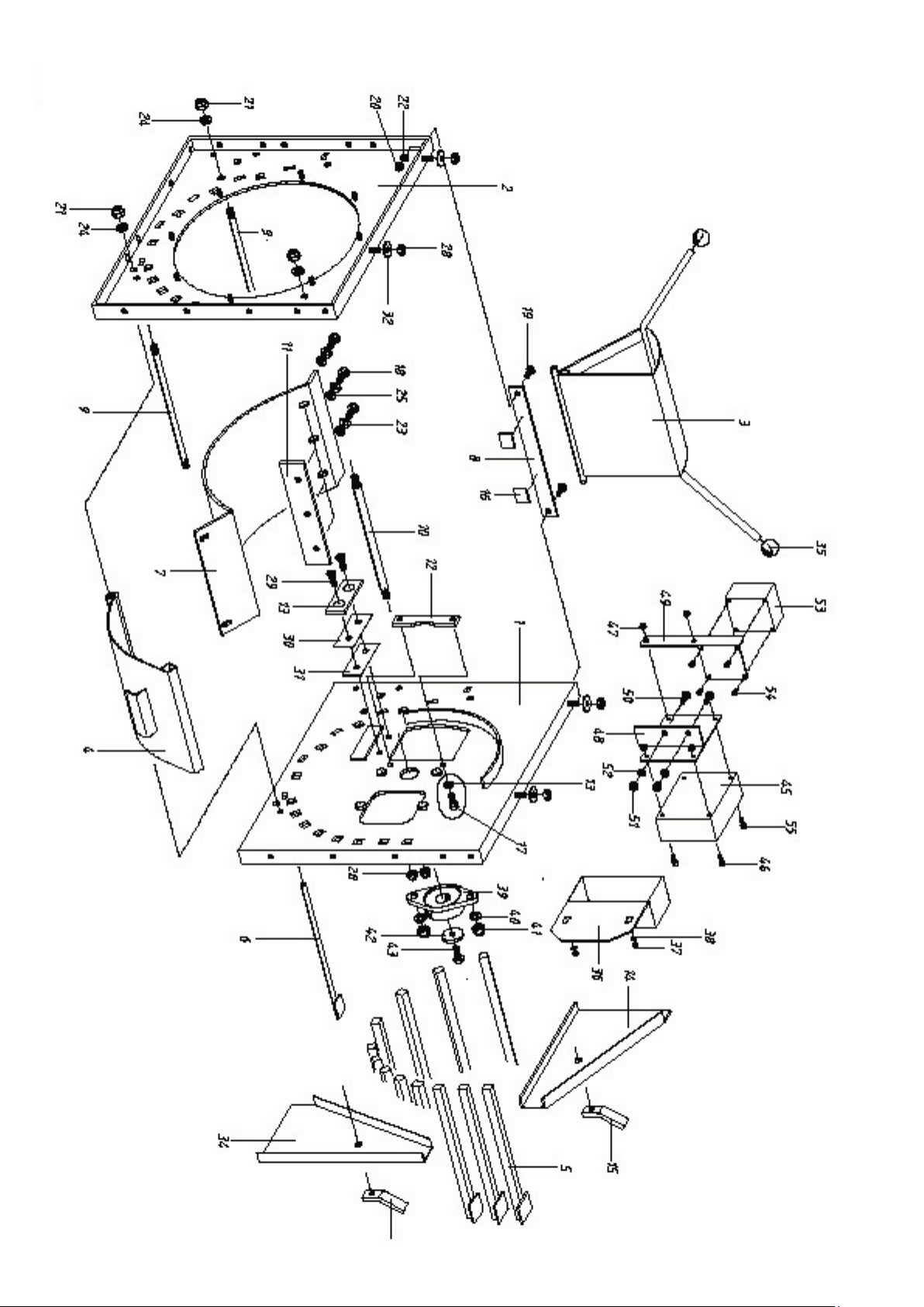
Shredder Frame GSE/GSB/GSZ 242
Pos. Description Nr. DIN Size
Electric version GSE 242
45 Star/Delta switch 50781
46 Socket head screw 51340 DIN 912 M 6x16
47 Self-locking hex screw 51606 DIN 985 M 6
48 Bracket for electric switch 12352
49 Emergency stop plate 12358
50 Hex screw 51444 DIN 933 M 8x20
51 Self-locking hex screw 51607 DIN 985 M 8
52 Lockwasher 51706 DIN 127 B 8
53 Emergency Box 50858 018572
Pos. Description Nr. DIN Size
Main frame
GSE/GSB/GSZ 242
1 Side plate, left 12275
2 Side plate, right 12084
3 Flap plate 12276 GSE 242
3 Flap plate 14229 GSB 242
3 Flap plate 14231 GSZ 242
4 Ejection steel baffle 12277
5 Hammer stop 12278
6 Stay-rod for lower chute 12279
7 Lower feedthrough plate 12280
8 Flap plate stop 12281
9 Tie rod 12282
10 Spacer rod 12283
11 Counter hammers 12284
12 Counter hammer, vertical 12094
13 Counter hammer, horizontal 12286
14 Hammer stops casing 12096
15 Sealing cap 12097
16 Foam rubber 12098
17 Socket head screw 52857 DIN 912 M 10x16
18 Hex screw 52622 DIN 933 M 10x18
19 Hex screw 51446 DIN 933 M 8x25
20 Self-locking hex screw 51607 DIN 985 M 8
21 Self-locking hex screw 51609 DIN 985 M 12
22 Lockwasher 51706 DIN 127 B 8
23 Lockwasher 51707 DIN 127 B 10
24 Lockwasher 51708 DIN 127 B 12
25 Washer 51649 DIN 125 10,5
28 Self-locking hex screw 51608 DIN 985 M 10
29 Socket head screw
w. hex recess. 51512 DIN 7991 M 10x30
30 Spacer plate 1 12099
31 Spacer plate 2 12100
32 Shim 51698 DIN 9021 10,5
33 Spacer shim 51636 12x24x1
34 Hammer stops casing 12101
35 Ball knob 50995 DIN 319 D=40 M12
Shredder Frame GSE/GSB/GSZ 242
- 17 -
Shredder Frame GSE/GSB/GSZ 242

- 18 -
Pos. Description Nr. DIN Size
Rotor, weldment
GSE/GSB/GSZ 242
1 Rotor 12303
2 Hammer shaft 12304
3 Mounting cover 12418
4 Side blades 12305
5 Hammer spacer shim 12130
6 Hammer 12131
7 Pulley 12306 GSE 242
7 Small vbelt pulley 12426 GSB 242
7 Belt pulley 12306 GSZ 242
8 Flange bearing (machined) 12078
9 Hex screw 51461 DIN 933 M 10x20
10 Washer 12133
11 Socket head screw with
hex recess 51512 DIN 7991 M 10x30
12 Self-locking hex nut 51608 DIN 985 M 10
13 Lockwasher 51708 DIN 127 B 12
14 Self-locking hex nut 51609 DIN 985 M 12
15 Slotted socket head
cap screw 51533 DIN 963 AM 8x25
16 Self-locking hex nut 51607 DIN 985 M 8
17 Feather key 51721 DIN 6885 A 8x7x28
18 Lockwasher 51706 DIN 127 B 8
19 Lockwasher 51707 DIN 127 B 10
20 Sealing plate 12145 GSE 242
20 Sealing plate 12419 GSB/GSZ
21 Hex screw 51444 DIN 933 M 8x20
22 Washer 51648 DIN 125 8,4
Rotor, weldment GSE/GSB/GSZ 242

- 19 -
Rotor, weldment GSE/GSB/GSZ 242

- 20 -
Motor bracket / Electric Power Drive /
belt casing
Pos. Description Nr. DIN Size
Motor bracket, weldment
GSE 242
1 Motor bracket 12260 GSE 242
2 Pressure screw 12149
3 Hex screw 51446 DIN 933 M 8x25
4 Self-locking hex nut 51607 DIN 985 M 8
5 Washer 51648 DIN 125 8,4
6 Hex nut 51595 DIN 934 M 12
7 Lockwasher 51706 DIN 127 B 8
Electric power drive
GSE 242
10 Motor 50740
11 Motor mount 12177
12 Lockwasher 51706 DIN 127 B 8
13 Self-locking hex nut 51607 DIN 985 M 8
14 Washer 51648 DIN 125 8,4
20 Washer 12133
21 Complete belt sheave 12268
22 Spacer bushing 12269
23 V-belt 51133 DIN 2215 13x1525 li
24 Hex screw 51461 DIN 933 M 10x20
25 Feather key 51727 DIN 6885 A 10x8x30
Belt casing, weldment
GSE 242
30 Motor casing 12184
31 Cover for power drive 12370
32 Spacer sleeve 12371
33 Front plate 12372
34 Hex screw 51444 DIN 933 M 8x20
35 Hex screw 51429 DIN 933 M 6x16
36 Self-locking hex nut 51607 DIN 985 M 8
37 Galvanized blind rivet nut 51777 M6 L=16
Motor bracket / Electric Power Drive / belt casing
This manual suits for next models
2
Table of contents
Other BGU Paper Shredder manuals

Popular Paper Shredder manuals by other brands

IDEAL
IDEAL 4107 operating instructions

UNITED OFFICE
UNITED OFFICE 100159 operating instructions

Formax
Formax FD 8400HS Operator's manual

STERWINS
STERWINS ESH1-40.3 Legal and Safety Instructions

Fellowes
Fellowes Powershred XC-6 manual

Champion Power Equipment
Champion Power Equipment 100472 Operator's manual


