BGU GSE 20 WOODY User manual

ORIGINAL USER’S MANUAL
Carefully read the entire manual before operating your
garden shredder!
GARDEN SCHREDDER
GSE 20 WOODY / GSB 20 WOODY
Südharzer Maschinenbau GmbH
Helmestraße 94 ∙ 99734 Nordhausen/Harz
Zentrale: 03631/6297-0 ∙ 7-111
Internet: www.bgu-maschinen.de
e-mail: [email protected]
We manufactu-
re in Germany
-Set-up
-Use
-Maintenance
-Accessories

2
CONTENTS
1. Introduction 3
1.1 About the manual 3
1.2 Delivery and transport claims 4
2. Product overview 5
3. Safety pictograms and warning labels 6
4. Safety 8
4.1 General safety rules 8
4.2 Mandatory application field 9
5. Operation 10
5.1 Setting-up and installing the machine 10
5.2 About electric powered versions 10
5.3 Operating gasoline/engine driven machines 11
5.4 Operating safety 12
6. Use of the shredder 13
6.1 Selecting the best discharge grate 14
6.2 Changing of a reducing grate 14
7. Handling and transportation 16
7.1 Long-distance transportation 16
7.2 Short-distance transportation 16
8. Repairs and maintenance 17
8.1 Ordinary maintenance 17
8.2 Daily cleaning operations 17
8.3 Tensioning and replacing the V-belt 17
8.4 Replacing the hammers 18
8.5 Replacing the side blade 21
8.6 Replacing the counter-blades of the side spout 22
9. Dismouting and discarding an obsolete machine 23
10. Technical specifications 24
10.1 Noise emissions 25
11. Wiring diagram 26
12. Trouble-shooting 27
13. Other areas of possible danger 28
13.1 Mechanical dangers 28
13.2 Electric dangers 28
14. Consumable 28
15. Legal warranty 29
16. Extended warranty 29
17. Replacement parts 30
18. EC-Compliance Statement 39

3
Dear customer,
thank you very much for your trust and preference in buying this gar-
den shredder! You have now joined the BGU worldwide family.
This shredder is available in different versions.
GSE 20 Woody with electric motor
GSB 20 Woody with gasoline engine
Various optional perforated outlet grates are available to match the
type of required compost material.
1.1 About the manual
Please take time to read this manual and learn to how operate and
maintain the shredder safely. For your easier reading this manual is
laid out in several sections. The sections are progressively numbered
1 through 18 and listed on the “content” page. The information, pictu-
res and technical data in this document reflect current or planned pro-
duct features, functions, and characteristics as of the publication date.
Because of on-going product improvements and feature additions, in-
formation in this document is subject to change without notice. If you
are experiencing a problem or functional trouble on your machine,
please read the “trouble-shooting” section to identify possible causes
and remedies. If the problem or functional trouble is not listed in the
trouble-shooting chart contained in this manual, ask your Authorized
Service Centre for service. When you order parts maintenance or
repair services, your Authorized Service Centre, your dealer or even-
tually the manufacturer need your machine serial number and engine
serial number. These are the numbers that you have recorded on the
product identification label of the manufacturer on the machine.
1. INTRODUCTION

4
1.2 Delivery and transport claims
Upon receiving the shredder at your place, please check for visu-
al machine damages such as damaged packing or scratched buckled
parts. If so, make a remark on all copies of the delivery bill before si-
gning for acceptance.
Also have the truck driver sign al copies of the delivery bill. Should
your shipper or the truck driver refuse to accept your claim, fully re-
ject delivery of the machine and make sure to inform us (the ma-
nufacturer) immediately. No claims will be taken into account by the
shipper or by the insurance company, if a reservation note is not ma-
de on the delivery bill. All transport damages must be notifi ed within
latest 2 days from delivery. Therefore delivery must be collected and
inspected within this term. Later claims shall be disregarded. In ca-
se of assumed but not visually clear transport damages make sure to
mark the following sentence on the delivery bill: „Reserved delivery
due to assumed transportation damages.“
Insurance and shipping companies act with extreme caution in case of
transport damages and sometimes refuse to accept responsibility.
Please make sure to provide clear and exhaustive evidence (photos)
of the claimed damages.
Thank you in advance for your help and attention to this matter.

5
2. PRODUCT OVERVIEW
Upper infeed hopper
Switch (electric versions only)
Caster wheels
Motor (electric motor or
gasoline engine )
Discharge chute
Control handle for
discharge chute
Side infeed spout
Belt drive housing

6
1. Personal protection pictogram
„Wear ear plugs and goggles“ when working with your shredder
2. Personal safety label
“Wear suitable protective gloves“
3. Machine safety label „Read before use“
To avoid personal injury or death, carefully read and understand
all instructions pertaining to the shredder including the engine
manufacturer’s operating and maintenance instruction manual.
4. Machine safety label „Read before use“
To avoid personal injury or death, carefully read and understand
all instructions pertaining to the shredder including the engine
manufacturer’s operating and maintenance instruction manual.
5. Machine safety label „Please mind this alert
sign“
To avoid personal injury or death, carefully read and understand
all instructions pertaining to the shredder including the engine
manufacturer’s operating and maintenance instruction manual.
6. Operation safety label “
Do not reach inside the infeed hoppers or the discharge chute with
your hands. VERY DANGEROUS!“
7. Operation safety label
Before setting-up, servicing, maintaining and cleaning the machine,
disengage all power and stop the engine.
3. SAFETY PICTOGRAMS AND WARNING LABELS
PH-6504, 6538 Auswurf geöffnet, geschlossen
Achtung! Gefahr für die Hände!
Drehrichtung beachten (nur PH-6504)
Vor Erstinbetriebnahme Seitentrichter....
7
8. Operation safety label
“Read before use and keep yourself and others at safe distance from
the dangerous area!”
This label reminds operator and bystanders of the dangerous
area between the tractor and the winch.
9. Warning label “ATTENTION! Direction arrow!“
This arrow shows the revolution sense of the motor. PLEASE CHECK
motor rotation at fi rst start.
10. Operation safety label
Effectively assemble and fi rmly secure the upper hopper and the si-
de spout on the machine before setup. Make sure that both the infeed
hopper and the side spout are duly set in working position before fi rst
use.
11. Operation safety label „Discharge chute ope-
ned/closed“
12. Production label „Product identifi cation“
This label shows the company details of the manufacturer and the
main machine technical data.
13. Identifi cation label „BGU-Logo“
PH-6504, 6538 Auswurf geöffnet, geschlossen
Achtung! Gefahr für die Hände!
Drehrichtung beachten (nur PH-6504)
Vor Erstinbetriebnahme Seitentrichter....
PH-6504, 6538 Auswurf geöffnet, geschlossen
Achtung! Gefahr für die Hände!
Drehrichtung beachten (nur PH-6504)
Vor Erstinbetriebnahme Seitentrichter....

8
Strictly perform installation, set-up, maintenance, cleaning
and transportation with the motor switched off and all moving
parts firmly secured against accidental operation.
The user shall strictly comply with these operation, set-up, mainte-
nance, repair and trouble-shooting instructions in order to assure safe
operation and no damages to the equipment. The owner must under-
stand these instructions and must allow only persons who understand
these instructions to operate the shredder. Moreover, we recommend
to let the machine be run only and strictly by trained and skilled staff
who must be familiar with the applicable occupational safety and health
administration rules as well as applicable transportation rules. Incorrect
use of the splitter can cause serious injury or death.
No person under 16 years should operate this log splitter.
The machine shall be installed and kept in a suitable location selected
by the customer for safest operation.
Make sure that the equipment stands on a safe stable foundation.
The working area around the machine must be kept as clear as possib-
le from surrounding obstacles and slippery foundation floors should be
duly treated (do not use saw dust or wood ash for this purpose).
4.1 General safety rules
● NEVER leave the machine unattended with the running motor.
● Switch the motor/engine off, disconnect power and secure the ma-
chine from unauthorized use of thirds before leaving the operator’s
station for any reason.
● Never allow anyone to stand in the dangerous area of the machine
while in operation.
● REMEMBER: the operator is responsible for safety of all nearby thirds
on site. Never direct the dischargeof material towards bystanders.
● Due and proper illumination of the working site must be provided at all times.
● To ensure stability during operation make sure to choose a flat, dry
floor free from any tall grass, brush or other interferences.
● Always wear suitable hearing (ear plugs or muffs) while operating the machine.
● Operators must wear steel toe safety shoes, tear-resistant gloves,
safety glasses and snug-fitting work cloths.
● Do not wear loose closing or jewellery that can be caught in moving
parts. Long pants, non-slip gloves and sturdy work shoes with non-
skid soles are recommended when working outdoors. Wear protecti-
ve hair covering to contain long hair.
● Sharp blades and hammers provide for optimum shredder perfor-
mance and prevent dangerous kick-back risk.
4. SAFETY

9
● Damaged or buckled blades (very likely to break during operation) should not be used.
●
Always wear work gloves to protect your hands while replacing worn blades/ham-
mers.
● Strictly ask a skilled licensed electrician for any intervention on the electric system.
● Operate the shredder in dry conditions. Using an electrical appliance in wet
conditions, such as rain or snow, or near a pool or sprinkler system could
result in damage to the on/off motor switch or to the electric motor itself.
● Strictly use mechanical tools (i.e. wood stocks) to turn and release jam-
med or skewed branched/sticks inside the hopper or the side spout. Ne-
ver reach with your hands inside the hopper or side infeed spout when
the machine is running.
Never attempt to remove a jammed piece of wood or material before
disconnecting/unplugging the machine from the power and before the
cutting tools (blades and hammers) have come to a complete stop.
● Do not try to defeat or override any safety features. Never operate the
machine without its protection safeties.
● Do not provide any additional customised protections or tools on board of
the machine, other than the ones designed and supplied by the manufac-
turer.
● Strictly use original spare parts of the manufacturer.
4.2 Mandatory application field
Garden shredders are designed to reduce brush, stalks, tree-bark and gar-
den waste to fine particle size. All other applications are forbidden and
considered as “misuse”. Make sure that no foreign matter (nails, screws,
stones or alike) in or on wooden material gets trapped in the machine.
This machine is not suitable for chipping stones, metals and glass,
plastic ropes/lines and other similar workshop material. Grass
and vignards waste should be stored for at least one week before
shredding.
This shredder can handle up to 65 mm diameter branches through the side
infeed spout and up to maximum 50 mm diameter in the upper hopper.
This machine is one-man operation only. Never use the machine indoor. It
is strictly designed for outdoor or very well aerated places.
Any other use or shredding method is considered by the
manufacturer as “misuse”. In case of misuse the manufacturer will
not be liable for any injuries or damages and the operator will be
held entirely responsible.
Misuse will immediately void your warranty!

10
To ensure stability during operation make sure to choose a
flat, dry floor free from any tall grass, brush or other interfe-
rences. If your floor/ground is soft, you may use a solid board
underneath your shredder.
Important! Set your shredder on an even, safe stable and non-
slip foundation.
5.1 Setting-up and installing the machine
Attention Danger! Strictly perform installation, set-up, main-
tenance, cleaning and transportation with the motor switched
off and all moving parts secured against accidental operation.
Immediately disconnect power off the machine in case of any
eventual fault or trouble.
Assemble and securely attach both upper hopper and side in-
feed spout on the machine before the first setup.
Do not operate the machine until all safeties and protections are duly
and efficiently in place.
To install the side infeed spout on the chipper, follow the in-
structions below:
Install the chipper on a stable and well levelled surface.
Check the counter-blades of the side spout and make sure that they are
securely and firmly in place.
Set the spout on the shredder so as to snap the 4 screws in the recesses
on the machine side flanks and tighten the screws to fix it (Fig. 1).
Strictly use the standard hardware that is supplied with the machine
(shims, lock washers and self-tapping hex nuts SW13).
Now manually cause the rotor to revolve and make sure that the blade
on the rotor disc does not hit against the side spout as it revolves. Now,
insert and close the safety contact. For shredders with electric power
motor, the safety contact is wired to the on/off switch. For shredder
versions with gasoline engine, the safety contact must be wired to the
engine.
Insert the safety contact in the contact retainer on the side spout (see
figure 2) and secure it with special M4 screws supplied along with the
machine (SW 3 and SW 7).
5. OPERATION
Fig. 1
Fig. 2
11
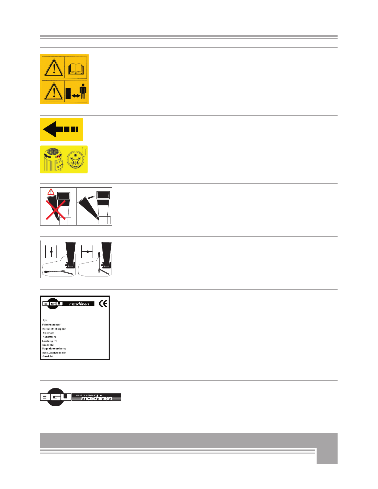
To install the upper infeed hopper on the shredder, follow the
instructions below:
Turn the 4 fixations screws (SW 15) on the upper side of the hopper
to make the threaded end of the screws advance by 2-3 turns in their
respective holes. Set the hopper on the shredder so to snap the 4
screws in the recesses on the machine side flanks. The lug with a star
knob must be located opposite to the side spout. Make sure that the
threaded rod is inserted into the bracket of the safety switch. Tigh-
ten all 4 fixations screws (see figure 3) while checking that the hop-
per keeps firmly in position on the shredder and that no gap is formed
between the upper hopper and the side flanks.
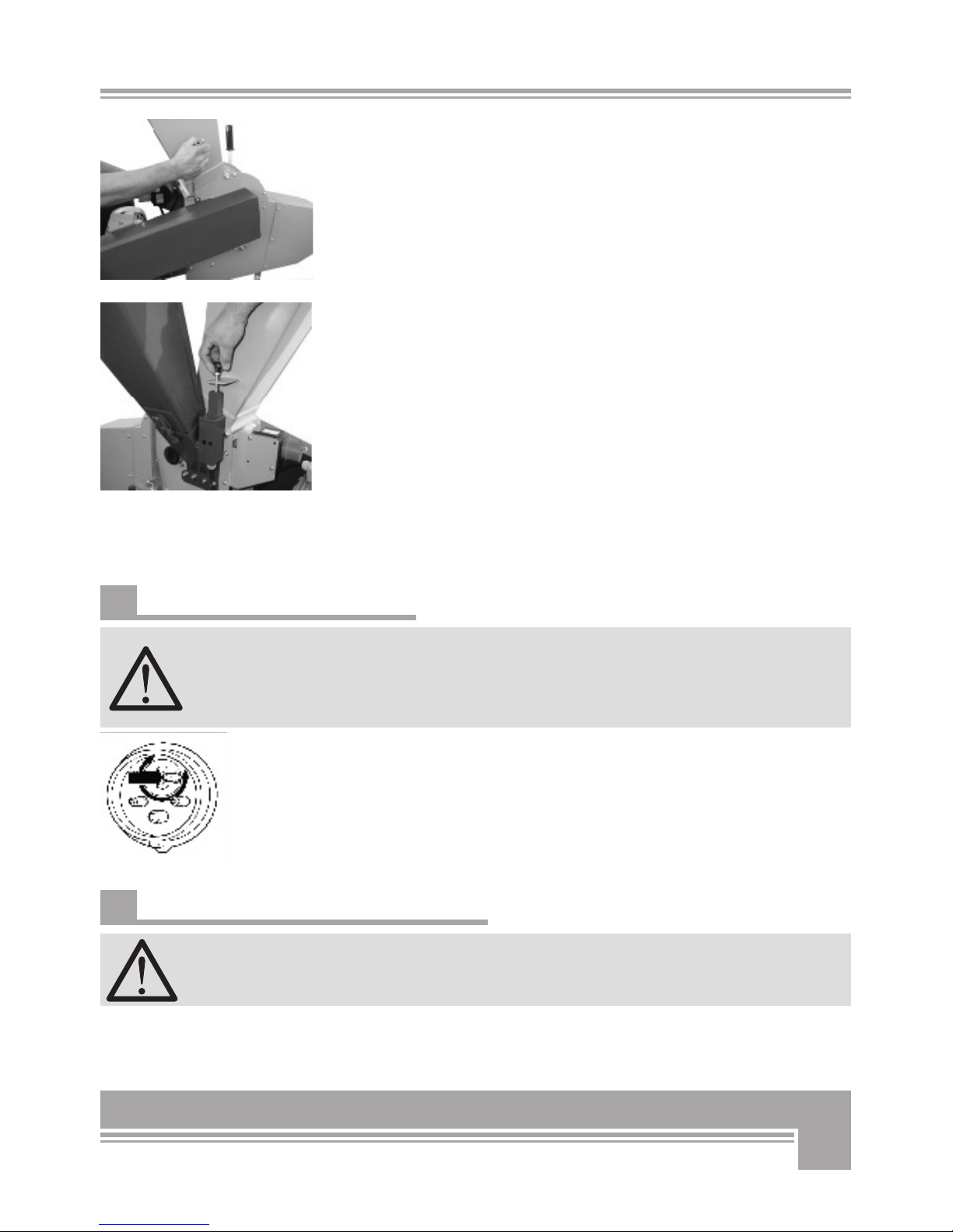
Now turn the threaded rod located on one side of the hopper to insert
it in the contact retainer of the side spout (see figure 4) and, there-
fore, to close the safety contact. Failure to sufficiently and complete-
ly turning the rod, will prevent successful starting of the shredder. Do
not move the locknuts of the threaded rod. If the nuts are excessively
tight against the thread and the star knob is further turned and inser-
ted in the contact, the safety switch might get damaged. Excessively
turning the nuts in the opposite direction, may prevent the threaded
rod to reach into the contact and therefore efficient starting of the ma-
chine.
5.2 About electric powered shredders
Plug the shredder and connect power. Three-phase, 400V mo-
tor versions should be powered using a power cord of at least
1,5mm² section. Unusually long power cords or cord extensions
should have a wider section (5x2,5 mm²). If you don’t feel famili-
ar with phase changing ask a licensed electrician to help you out.
Before pressing the green on-switch and starting to work, quickly switch
the 400V motor on and off to check that rotation is performed in the di-
rection shown by the arrow on the motor casing. Should rotation be per-
formed in the opposite direction, immediately stop the motor and use a
phase inverter to switch the polarity in the plug of main power cord using
a phase changer. bPress down the insulating disc inside the plug using a
screwdriver and then turn it by 180°. (see figure „Phase inverter “).
5.3 Operating gasoline/engine driven machines
Perform maintenance, cleaning and repairs of gasoline engine
in accordance with the instructions of the manufacturer.
Gasoline shredders are equipped with centrifugal clutch in order to
greatly facilitate starting of the engine.
Fig. 3
Fig. 4
Phase inverter
12
The clutch’s purpose is to disengage when the engine is idling so that
the rotor does not move.
When the engine speeds up (approx 1800 l/min) because the operator
has pulled the throttle trigger to begin shredding, the clutch engages
so that the rotor can start turning.
The rotor reaches its rated speed when the gasoline engine runs at
max speed (approx. 3600 1/min).
You can only switch the engine off, when the engine has slew down
and the idle speed is reached.
5.4 Operating safety
The shredder cannot start unless all safeties and guards, the
infeed hopper/spout, the discharge chute and the pulley cover
are duly in place and functioning.
Check for the threaded rod on the upper infeed hopper to be suffi-
ciently inserted into the contact holder so that the safety contact is
disengaged and the shredder can start.
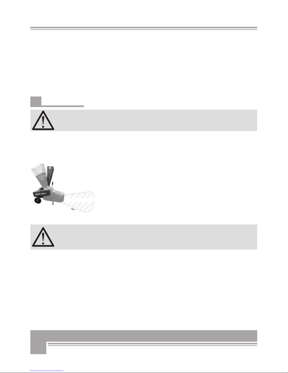
Attention! Do not allow any bystander in the dangerous area of the
machine (see figure 5).
WARNING: shredded material escaping from the discharge-chute work
area can be scattered at very high speed.
A low-volt release switch is provided on board to protect the machine
in the event of a power blackout. The shredder must be restarted af-
ter each blackout.
A thermal switch is provided in the on/off switch of the electric motor
in order to stop the machine in the event of a possible overload. In
this case, let the shredder standstill and cool for approximately 5.10
minutes before restarting.
When stopping the machine, remember that the rotor will keep
turning for about 30 more seconds lag time.
Take due measures to avoid hands contact with the infeed
hopper/spout and the discharge chute during this time!
Fig. 5
dangerous work area

13
When all safeties, guards and protections are on board, you
may start working with your shredder. Dress properly, wear
long pants, non-slip gloves, sturdy work shoes with non-skid
soles and suitable personal protection implements when wor-
king outdoors.
Switch the shredder on.
Feed brush, stalks, tree-bark, leaves, thin branches and garden waste
into the upper hopper to reduce them into fine particle size by means
of special hammers and discharge the compost out of the lower chute.
The machine optimum intake is set by the manufacturer before ship-
ment. However, check for throughout smooth and fast pulling when
feeding long, thin material into the hopper. Thicker branches and sticks
(> 30mm) should be fed slower into the machine.
The machine is equipped with a spring-loaded reducing grate. Should a
stoppage or an overload situation occur, the grate is flapped forwards
so that the crushing rotor can start freely turning around. This system
was conceived and designed to prevent shredder overloads.
Move the shredder away, as soon as an excessive quantity of shredded
material falls down onto the ground under the chute output.
Should the grate open too frequently or too easily, adjust the pre-loa-
ding of the spring by means of the eyebolt. To do so, first adjust the
hex-nut (SW 13) of the eyebolt closer to the spring (see „Figure 6“).
Various kinds of grates are available to adjust the system to the va-
rious kinds of required compost (see “Selecting the best discharge gra-
te”).
The side spout allows chipping thicker tree limbs by means of high-ca-
pacity cutting blades. Before feeding limbs into the side spout, make
sure to clean it and remove all projecting branches. Now, insert your
material into the side spout. As it passes within a heavy steel anvil
(rotor), this blade shears off a chip of wood once for every revoluti-
on. The own-weight of this compact, but powerful chipping action and
the special knife design assure optimized intake and discharge of the
shredded material without further pushing it.
6. USE OF THE SHREDDER
Fig. 6
14
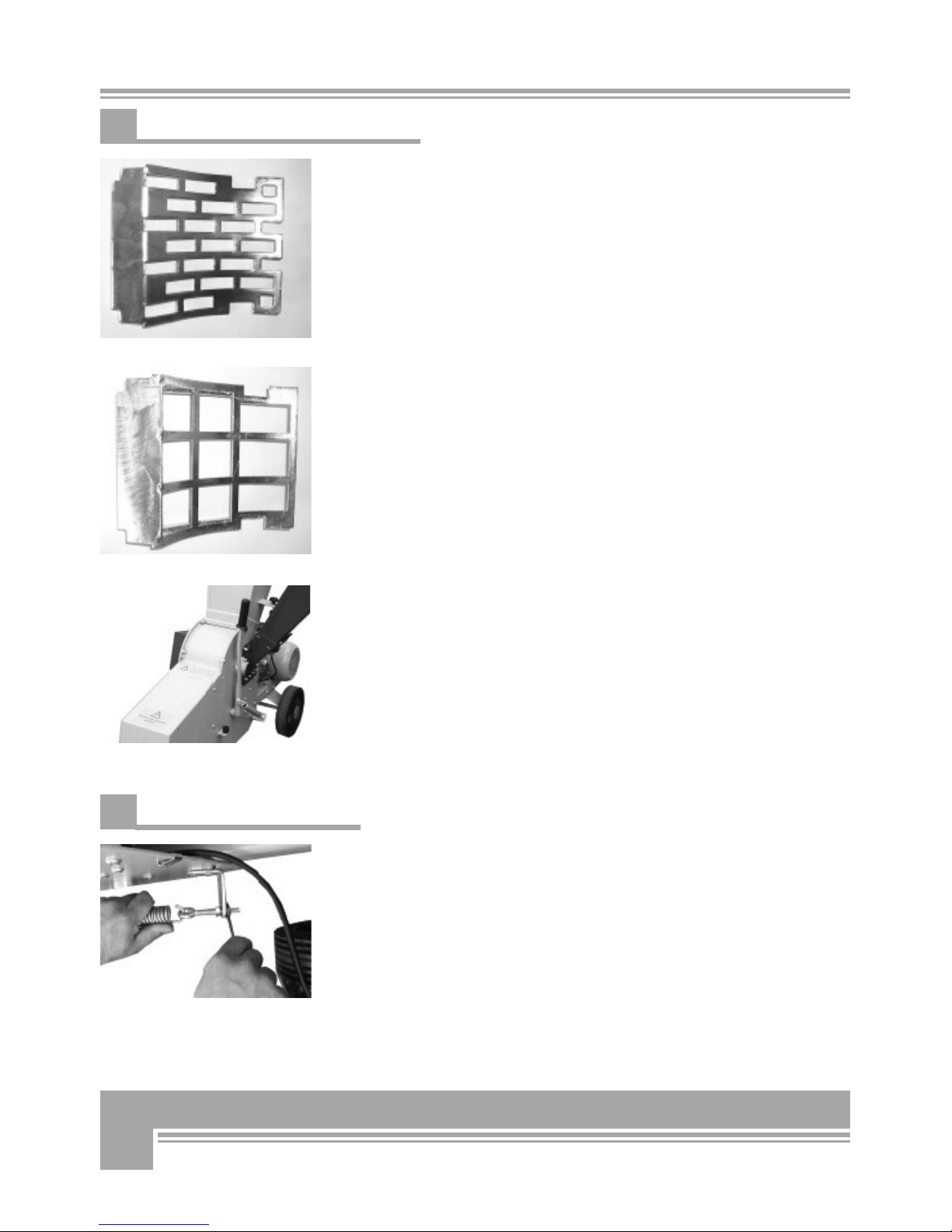
6.1 Selecting the best discharge grate
The machine is equipped with a standard grate suitable for compos-
ting bushes and branches (see „Figure 7“).
If you require shredding of very wet material (fresh grass, thistles,
stinging nettles etc…) preferably use a larger perforated grate, in or-
der to avoid stoppage of the machine. When you are to chip humid,
clumpy materials, make sure to mix them with some other wooden
material so that the rotor remains clean and no jamming occurs.
Differently perforated grates allow for adjustment of your compost
production (see Figure 7 and 8).
Larger holes correspond to larger compost size.
Should frequent stoppage occur on the discharge chute, it is recom-
mended to select a wider-mesh grate.
Should material keep jamming in the chipper and failing to reach the
discharge chute, flip the grate over. To do so, push down, the lever on
one side of the machine. (see „Figure 9“).
6.2 Replacing a reducing grate
Make sure that the machine is fully disconnected and all moving parts
are secured before performing any maintenance/repair work on the
machine.
To replace a worn-out grate, do the following:
Remove the tension spring by lifting the adjustment handle up. Re-
lease the hex nuts (SW 13) on the eyebolt (see „Figure 10“) and final-
ly unhook the spring and push the handle down again.
Fig. 7
Fig. 8
Fig. 9
Fig. 10

15
Release the hex nuts (SW 13) on the opposite shredder side and re-
move the bushing (see „Figure 11“).
Now pull out the adjustment handle from the side (see „Figure 12“).
At this point the grate should be falling off and be freely and easily
removable.
To fit a new grate in, insert the handle back into its hole on the shred-
der flank while firmly holding the grate in place between the two side
flanks of the shredder so that the adjustment handle can be slipped
into the channel of the grate.
Fit the bushing on the opposite side of the handle and tighten the hex
screws (SW 13) back in place making sure to avoid twisting and strai-
ning of the handle square tube.
At the end, check the handle for proper functioning: with the hand-
le lifted up, the discharge chute must be closed and it should open as
you push it back down.
Hook the spring back in place using the safety eyebolt and respective
hex nut to secure the handle.
Provide for due stretching of the spring, making sure that the eyebolt
thread stands about 20 mm out.
.
Fig. 11
Fig. 12

16
Attention! When handling electric equipment, make sure to
disconnect power before performing even just a short-distance
handling.
7.1 Long-distance transportation
Long-distance transportation requires shredder handling asset.
Clean the chipper thoroughly to avoid dirt and splinters to contamina-
te public roads and walkways.
Release the lock on the side spout and secure it to the hopper by
means of the special star-knob.
In this asset, the dimensions of the shredder are smaller. With the
spout folded up, the shredder is only 700 mm wide and can be pulled
through any door and corridor.
Hold the upper rim of the hopper with one hand and pull slightly back
to lean the shredder and start pushing to whatever direction. (see
„Figure 13“).
7.2 Short-distance transportation
For moving the machine to any other work place at short-distance,
you do not need to fold up the side spout.
Simply hold the upper rim of the hopper with one hand and pull
slightly back to lean the shredder and start pushing to whatever direc-
tion. (see „Figure 13“).
7. HANDLING AND TRANSPORTATION
Fig. 13

17
Attention!
Before performing any maintenance/repair work on the machi-
ne, make sure that the machine is fully disconnected from power.
8.1 Ordinary maintenance
Make maintenance a regular part of daily operation. The daily
maintenance routine needs to include:
• Cleaning of the machine and clearing of all parts from residual wood
debris, chips, dust, bark pieces and eventual other waste. Ideally
perform a last shredding cycle using some dry branches and bushes
whose passage through the drum will produce a sort of a self-clea-
ning effect.
• Greasing of the centre of rotation of the outlet grate.
• Regularly check the V-belt tension and perform new stretching if
required.
• Regularly check the conditions of the blades, the copunter-blades
and the hammers for unusual wear.
• Tighten all screws and nuts after the first operation hour.
• Tighten all screws and nuts again after each 100 operation hours.
8.2 Cleaning the machine at the end of a workday
Clean the machine and clear all parts from residual wood debris, chips, dust
and bark pieces that may have formed there during normal operation.
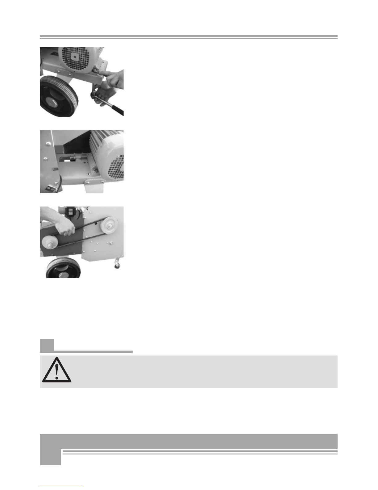
8.3 Tensioning and replacing the V-belt
Attention! Before performing any maintenance/repair work on the
machine, make sure that the machine is fully disconnected, that all
moving parts have come to a still stand and are duly secured.
To check for correct tensioning of the V-belt, first remove the belt co-
ver. To remove the cover first release the screw 1 (SW 10) and the
nuts 3 (SW 10) (see „Figure 14“). A duly stretch V-belt shall not sag
more than 10 mm under the pressure of a single finger.
To remove or to stretch the V-belt, first release the 4 fixation screws
(SW 13 - SW 17) on the motor without pulling them completely out of
their place.
8. REPAIRS AND
MAINTENANCE
Fig. 14
18
To replace a worn out V-belt or simply to stretch it, release (but do
not pull out) the 4 adjustment screws (SW 13 or 17) of the motor ba-
se plate (see „Fig. 15“).
To stretch a loose V-belt, simply tighten the tensioning screws (SW
17) located on the motor base plate and turn them towards the motor
mount (see „Figure 16“) after having released the lock nut (SW 17).
Now stretch the V-belt till it will sag by approx 10 mm under the pres-
sure of one finger, (see „Figure 17“).
The motor must be parallel to the outer profile of the motor bedplate.
Finally tighten again all 4 screws (SW 13 and SW 17) to operate the
motor again.
To replace a worn out V-belt, release the 4 adjustment screws (SW
17) so that it will be possible to move the motor back towards the ro-
tor.
Dismount the V-pulley off the belt pulleys.
Now, fit a new one in and provide due tensioning as described above.
Tighten and secure all 4 fixation screws (SW 13 and SW 17).
After complete stretching of the V-belt fit the cover back in place on
the chipper.
8.4 Replacing the hammers
Attention! Always use safety work gloves! Strictly perform
maintenance, repair and cleaning services after you have suc-
cessfully disconnected power and after all moving parts on the
machine have come to a complete still stand.
As soon as you detect a reduction of the chipper output and producti-
vity, check the hammers and eventually perform regrinding or repla-
cing.
Fig. 15
Fig. 16
Fig. 17

19
VERY IMPORTANT: you may not regrind and reuse the same ham-
mers for more than two times. To regrind, dismount and take the
hammer off the machine, regrind using a suitable sharpener and final-
ly fit the hammer back in.
To replace a hammer follow the instructions below:
• Release (without fully removing) the 4 fixation screws (SW15) and
remove the upper infeed hopper (see figure 15). When doing this,
remember to first pull out the threaded stud of the safety switch.
• Release the 4 hex nuts (SW13) and remove the side spout (see „Fi-
gure 19“).
• Unscrew the V-belt cover (SW10) (see „Figure 20“).
• Turn the rotor till the hammer pivots becomes visible through the
opening.
• Release and pull out the countersunk screw (SW 6) of the hammer
pivots (see „Fig. 21“)
Fig. 18
Fig. 19
Fig. 20
Fig. 21

20
Please note: countersunk screws are securely seated by means of
high resistance hardware loctite. Before attempting to remove them,
use an hot air gun (or similar tools) to warm them up. (see „Figure
22“).
• On the opposite screw side you will find a free seating area on the
hammer shafts for use of a forked key (SW13) that you can use to
hold the rotor shaft firm. (see „Figure 21“)
• Release the hex screw (SW 6) to pull them out.
• On the side flank of the belt cover there is a access opening (large
hole). Keep turning the drum till you can pull it out of through this
opening. Press the shafts down and let let pop-up before pulling it
out. (see „Figure 23“).
• Remove hammer and spacer from the shafts and lay them on the
side in the same dismount sequence.
• When fitting the new hammer in, press and hold the shafts against
the opposite side as the access opening and fit the new hammer in,
through the same access.
• While fitting the new hammer in, make sure to have a spacer al-
ways set between one and the other hammer.
IMPORTANT: assemble the hammers and bushings back on
the chipper in the order as they were taken out to avoid
eventual possible unbalanced rotor weight!
• Secure all hammer fixation screws using high resistance thread
glue.
• Hand turn the rotor to make sure that no hammer hits against the
shredder walls or other components and in that case grind excess
material off.
• After replacing the hammers of all three shafts, reassemble the side
spout by tightening the screw (see „Fig. 24“).
• Reassemble the side spout and make sure that the threaded stud
fits back into the safety contact holder, tighten all 4 hex screws (SW
15) by the original torque (see „Figure 25“).
• Screw the belt cover back in place (see „Figure 26“).
• Turn the threaded stud inside the contact holder.
• Start the shredder. Failure of the machine to properly start, turn
the stud to further progress inside the contact holder turn until the
safety switch is engaged.
Fig. 22
Fig. 23
Fig. 24
Fig. 25
Fig. 26
This manual suits for next models
1
Table of contents
Other BGU Paper Shredder manuals


