BI 399 User manual

Air-Jacketed Large Capacity
Flo-Thru CO2Incubators
Model No.
399
399-1
399GWH
057-641-00 • 6/8/05

Safety Information ........................................................................................................................................................3
Alert Signals ..........................................................................................................................................................3
Specifications ..............................................................................................................................................................4
Electrical Requirements ........................................................................................................................................4
Temperature Range ..............................................................................................................................................4
Temperature Control..............................................................................................................................................4
Uniformity in Chamber ..........................................................................................................................................4
Gas Flow Rates ....................................................................................................................................................4
Volume ..................................................................................................................................................................4
Humidity ................................................................................................................................................................4
Dimensions ............................................................................................................................................................4
Shelves ..................................................................................................................................................................4
Net Weight ............................................................................................................................................................4
Options ..................................................................................................................................................................4
Unit’s Environmental Operating Conditions ..........................................................................................................5
Unpacking and Installation ..........................................................................................................................................6
Shipping Carton ....................................................................................................................................................6
Location ................................................................................................................................................................6
Electrical Power ....................................................................................................................................................6
Shelf Positioning ..................................................................................................................................................6
Adjustable Screw Guards for Protecting Back of Unit ..........................................................................................7
Hooking Up Water ................................................................................................................................................7
Connecting Condensate Drain to the Incubator ....................................................................................................7
Air/CO2 Hook-Ups ................................................................................................................................................8
CO2 Connection: Standard and Siphon Type CO2 Gas Cylinders ......................................................................9
Operation....................................................................................................................................................................10
Auto Tune ............................................................................................................................................................12
For Best Results ..................................................................................................................................................12
Auto-Tuning Procedure........................................................................................................................................12
Temperature Calibration ......................................................................................................................................13
Setting the Hi-Limit Thermostat ..........................................................................................................................14
Loading the Incubator..........................................................................................................................................14
Air/Gas Ratio ......................................................................................................................................................15
Humidity Adjustment............................................................................................................................................16
CO2 Sampling/Measurement ..............................................................................................................................16
Air and CO2 (or Nitrogen) ..................................................................................................................................16
Humidification ......................................................................................................................................................17
Humidifying without the Optional Humidifier ................................................................................................17
Humidifying with the Optional Humidifier......................................................................................................17
About the Kind of Water to Use ....................................................................................................................18
Demineralizer Cartridge................................................................................................................................19
Operation of Humidification System ............................................................................................................20
Periodic Cleaning and Inspecting of Humidifier............................................................................................20
Humidity Controller ......................................................................................................................................22
Auto Tune ....................................................................................................................................................23
Offset Humidity Calibration ..........................................................................................................................23
Operating Suggestions ................................................................................................................................24
Hints on Using Fyrite ..........................................................................................................................................25
Taking a Fyrite Reading...................................................................................................................................... 26
Kwik Inject Automatic CO2 Recovery System ....................................................................................................29
Built-In Compressed Air Supply ..........................................................................................................................29
Maintenance ..............................................................................................................................................................30
Replacing Temperature and/or Humidity Controller ............................................................................................30
CO2 and Air Bubbler............................................................................................................................................30
Adjusting Automatic CO2 Recovery System ......................................................................................................31
Replacement Parts ....................................................................................................................................................33
Ordering Procedures ..................................................................................................................................................34
Decontamination Statement ......................................................................................................................................35
Two Year Limited Warranty ........................................................................................................................................36
Table of Contents

The Barnstead|Lab-Line Large-Capacity, 34 cu. ft. (963
liter), Flo-Thru CO2 Incubator has been specially
designed for laboratories that handle a high volume
of work. The unit has been factory tested and needs only
to be placed in a suitable location and connected to the
required electrical supply and air and CO2 (or nitrogen)
sources at a pressure of 15 psi. A blower fan assists in
maintaining uniformity of the CO2 concentration in the
chamber, as well as, minimizing any temperature gradi-
ents.
All controls are contained in the control panel. The micro-
processor- based controller maintains temperature from
slightly above ambient to 60ºC. The hydraulic hi-limit
thermostat controls temperature a few degrees above the
user established set point in the event the main controller
fails. This provides an added measure of protection to
the chamber.
The KWIK-INJECT™ system provides quicker recovery
and a more stable chamber environment. CO2 is inject-
ed into the chamber to compensate for losses incurred
during door openings. A timer on the control governs
injection time from 3 to 60 seconds.
6 perforated stainless steel shelves provide a total area of
36 sq. ft. (3 sq. m) with a load capacity of 100 lbs. (45 kg)
per shelf when the load is evenly distributed, 65 lbs. (29
kg) per shelf when the load is concentrated.
Humidification may be obtained simply by placing a pan
of deionized or distilled water on one of the shelves. A
humidifier and controller are available as factory-installed
options and require a demineralized water source. The
humidifier is controlled from the front panel and allows
regulation of the relative humidity from approximately
20% above ambient to 98% RH. A panel meter gives a
direct reading of relative humidity.
The exterior of the incubator is made from cold rolled
steel with a durable powder coated finish. The interior
and door are made of stainless steel. Inside the door and
between the double walls is 3-inch thick glass wool insu-
lation that helps hold heat loss to a minimum and pro-
motes temperature uniformity in the chamber.
Model 399GWH has an optional humidifier with controller.
Safety Information
Warning
Warnings alert you to a possibility of
personal injury.
Caution
Cautions alert you to a possibility of
damage to the equipment.
Note
Notes alert you to pertinent facts and
conditions.
Hot Surface
Hot surfaces alert you to a possibility of
personal injury if you come in contact
with a surface during use or for a period
of time after use.
Alert Signals
3

4
Electrical Requirements
399, 399GWH: 120 Volts, 50/60 Hz, 1400 Watts, 11.7 Amps
399-1: 230/240 Volts, 50/60 Hz, 1400 Watts, 5.8 Amps
Temperature Range
Ambient +5°C to 60°C
Temperature Control
±0.5°C
Uniformity in Chamber
±0.5°C
Gas Flow Rates
Air: 1.0 to 14.0 liters/minute
CO2: 0.1 to 1.2 liters/minute
Volume
34 cu. ft. (963 liters)
Humidity
Range: ambient to 98% RH
Accuracy: ±3% RH
Dimensions
Exterior: 42”W x 35”D x 91”H (107cm x 89cm x 231cm)
Chamber: 36”W x 25”D x 65”H (91cm x 64cm x 165cm)
Specifications
Shelves
6 perforated, stainless steel
Net Weight
980 lbs. (445 kg)
Options
H: Humidity Control
L: Left Hand Door
P: Built-in compressed air supply
GW: Glass Window 12” x 48” (30 x 122 cm)

Unit’s Environmental Operating Conditions
Pollution Degree: 2
Installation Category: II
Altitude: 2000 meters MSL (Mean Sea Level)
Humidity: 80% maximum, non-condensing
Electrical Supply: 120VAC or 240VAC
Voltage Tolerance: ±10% of normal rated line
Temperature: 15°C to 40°C
Product Usage: This product is intended for use indoors only
5
SPECIFICATIONS

6
Shipping Carton
The shipping carton should be inspected upon delivery.
When received, carefully examine for any shipping dam-
age before unpacking. If damage is discovered, the deliv-
ering carrier should both specify and sign for the damage
on your copy of the delivery receipt.
Open the carton carefully making certain that all parts are
accounted for before packaging materials are discarded.
After unpacking, if damage is found promptly report it to
the carrier and request a damage inspection promptly.
IMPORTANT: Failure to request an inspection of damage
within a few days after receipt of shipment absolves the
carrier from any liability for damage. You must call for a
damage inspection promptly.
Location
Select a location for the incubator that is free of drafts
and extraneous vibrations. The unit should be level.
Electrical Power
Turn all controls to the off position. Connect the power
cord of the incubator to an outlet providing the power
characteristics specified on the unit's nameplate or in this
manual.
Shelf Positioning
The 6 perforated stainless steel shelves are adjustable on
1/2" (12 mm) centers. Place the shelf support clips
where desired and then set shelves in place. Shelves
and support clips can be ordered to provide additional
shelf space.
Unpacking and Installation
Warning
Do not use in the presence of flam-
mable or combustible materials or
explosive gases. Do not use in the
presence of pressurized or sealed
containers. Fire or explosion may
result, causing death or severe
injury.
Warning
Do not heat any substance above a
temperature that will cause it to emit
toxic fumes. Death or severe injury
may result.
Warning
Use only an inert gas such as car-
bon dioxide in the incubator. Do not
under any circumstance inject oxy-
gen or other explosive gas or mix-
ture into unit. Failure to observe
these precautions can result in
explosion and/or fire and serious
injury or death to personnel and
property damage.

7
Adjustable Screw Guards for
Protecting Back of Unit
Exercise care in placing the back of the unit against a wall
to avoid damage to CO2 tubing and related attachments.
To protect against this, 2 adjustable screw guards on the
back are used to establish a buffer zone for the CO2 tubing.
If unit is shipped upright, guards are in place; if shipped flat,
guards are furnished loose and must be inserted.
Hooking Up Water
Connect supply water line to the 1/4” NPT fitting located on
the inlet side of the D. I. cartridge. The recommended
water pressure setting on the regulator gauge should be
adjusted to read between 10 and 15 psi.
Connecting Condensate Drain to
the Incubator
1/2” drain lines are located in back of the incubator.
UNPACKING AND INSTALLATION

8
Turn all flow meters on the incubator fully clockwise (closed).
Connect air and CO2 supply lines to their respective fittings on
the back of the unit. Use 1/4" (6 mm) ID tubing, flexible metal
hose, etc., (meeting local codes), with filters to ensure that the
air and CO2 are free of contaminants, for gas lines.
Set the supply regulators at 15 psi. Check all of the connec-
tions for leaks.
UNPACKING AND INSTALLATION
Air/CO2 Hook-Ups
Turn the power switch to OFF and insert the plug into the outlet.
To Air Fitting
To CO2 Fitting
100% Air 100% CO2
1/4" Hose Barb
Connections
Set pressure at 15 psi.
Pressure regulators and gauges must be
installed on each tank. Check local gas suppli-
er for proper regulators.
If air pump is used instead of tank, air must be
filtered to remove water, oil and dirt.
Warning
High concentrations of carbon diox-
ide produce metabolic abnormalities,
disturbances of the central nervous
system and cardiac instability.
Unconsciousness may occur at con-
centrations above 10%.
Note
It is our recommendation that this
unit run 24 hours empty before intro-
ducing media to be incubated. This
will facilitate ease of servicing if
required as well as nullify the need
to decontaminate the chamber in the
event a problem occurs.
This unit cannot be accepted for
servicing or credit by Barnstead
International unless accompanied by
a completed Certification of
Decontamination form, included at
the end of this manual.

Standard Type (Correct) Siphon Type (Incorrect)
1
2
3
12
3
4
5
6
7
8
1. Compressed Gas Association #320
connector.
2. Gas head space.
3. Liquid CO2 filled to 68% equal weight
of water that cylinder would hold at
60ºF.
1. Warning tag indicating that cylinder is siphoning type.
2* Aluminum ring.
3* Gold band.
4* Stamp or marking on cylinder: "Siphon" or "Eductor
Tube".
5* Valve should be of special type for service.
6* Withdrawal tube draws up the liquid CO2.
7* Gas head-space.
8* Liquid CO2 filled to 68% equal weight of water that
cylinder will hold at 60ºF.
*Note: Some gas suppliers will have no markings to indicate
an “Educator Tube” or “Siphon” type cylinder. Be sure to order
DRY, LAB-GRADE CO2.
Be sure to obtain a dual-stage regulator from the gas supplier
for the CO2 tank that is to be installed according to local
codes. Connect 1/4" ID (6.35 mm) flexible tubing to the regu-
lator. Connect the other end of the tubing to the unit's CO2
inlet (located on the back top panel). Insert tubing over hose
barb and fasten with an appropriate clamp to assure a proper
connection. Adjust the regulator for the pressure recommend-
ed on the previous pages when CO2 is to be injected into
chamber. For optimum results, do not exceed or reduce this
pressure.
CO2 Connection: Standard and Siphon Type CO2 Gas Cylinders
9
UNPACKING AND INSTALLATION
10
Operation
Amicroprocessor-based automatic tuning controller with a
platinum RTD temperature sensor provides a display of
either chamber or set point temperatures. The micro-
processor used in the unit automatically tunes PID
parameters to fit the characteristics of individual thermal
systems.
Auto-tune is a user-initiated function. It provides a tune-at-
temperature function that means the controller runs the
auto-tune program when the incubator is at set point.
Program parameters are retained in the nonvolatile mem-
ory in the event that there is power failure or interruption.
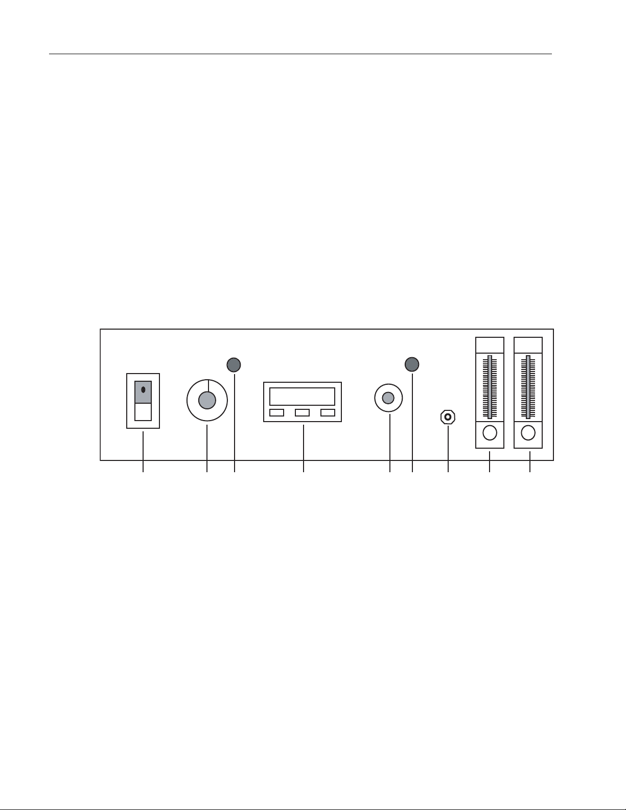
1 2 3 4 5 6 7 8 9
1. Power Switch
2. Hi-Limit Thermostat
3. Hi-Limit Thermostat Status Lamp
4. Temperature Controller
5. Kwik-Inject Control Dial
6. Kwik-Inject Status Lamp
7. Sample Access Port
8. Air Flow Meter
9. CO2 Flow Meter

1. CONTROLLER SELF-TEST: When the incubator is
powered up, the controller will display 8888 along with
three decimal points and the heat ON indicator lamp will
light. The display will then blank out for 2 seconds before
showing the chamber temperature.
2. HEAT ON INDICATOR:The heat ON indicator lamp is
lit when the chamber heater is receiving power. The lamp
will normally flash when the chamber temperature is at
set point.
3. SET POINT ADJUSTMENTS:The temperature con-
troller normally displays the chamber temperature. To
view or change the temperature set point proceed as fol-
lows:
A. Press and hold the star key and use either the
up or down arrow key to adjust the set point to
the desired temperature. Release the star key.
B. Allow at least 1 hour for the chamber tempera-
ture to stabilize.
11
OPERATION
Chamber or Setpoint Temperature
Heat Indicator
37.0
✱▼▲
Press Controller
✱View setpoint
✱▼ Decrease setpoint
✱▲ Increase setpoint

12
Auto Tune
The auto-tune program automatically adjusts the con-
troller parameters to achieve optimal temperature control.
It is not necessary to run the auto-tune program when
setting up the incubator. However, if the temperature
appears to be unstable, the auto-tune program can be run
using the procedure shown below:
For Best Results
• Set the usual set point temperature and use nor-
mal load conditions.
• Allow the incubator to stabilize at set point for at
least 1 hour.
Auto-Tuning Procedure
1. Enter the program mode by pressing and hold-
ing BOTH the up and down arrow keys for 3
seconds.
2. Release BOTH arrow keys when tunE is dis-
played.
3. The controller display should now be alternating
between tunE and oFF.
4. Press and hold the “STAR” (✱) key. Press and
release the up arrow key until At.SP is dis-
played. Release the “STAR” (✱) key.
5. After one minute has elapsed, the controller dis-
play will begin to alternate between showing the
chamber temperature, tunE and At.SP.
6. Allow the program to run until the display again
shows only the chamber temperature.
FEATURES

13
Temperature Calibration
1. Place a calibrated thermometer inside the cham-
ber on the corner shelf. Close both doors.
2. Press and hold the “STAR” (✱) key and using
the up or down arrow key, adjust the set point to
the desired temperature.
3. Allow the unit to run for at least 1 hour.
4. The controller display should now be indicating
the set point temperature. Make note of the ther-
mometer reading.
5. Press and hold both arrow keys until the con-
troller display indicates tunE. Release the arrow
keys. Press and release the down arrow key,
the display should now indicate LEUL. Press
and hold the “STAR” (✱) key and using the up
arrow key adjust the display to read 3. Release
the “STAR” (✱) key. Press and release the up
arrow key until the display indicates Zero. The
display should now alternate between Zero and
a numerical value.
6. Using the examples shown below and the ther-
mocouple value obtained in step above, enter
the correct Zero value into the controller using
the up or down arrow keys. If there is already a
Zero value present then add the new value to
the one already present.
7. When the correct Zero value has been entered,
press and hold the two arrow keys together until
the display again indicates the chamber temper-
ature. If the procedure was done correctly, the
controller display should now agree with the
thermometer reading to within ±0.5ºC.
OPERATION
Thermometer = 60°C
Controller Reading = 65°C
Subtract = -5°C
Enter Zero value of -5°C
Thermometer = 70°C
Controller Reading = 65°C
Subtract = +5°C
Enter Zero value of +5°C

8. Allow the unit to run for at least 1 hour.
9. Re-check the thermometer reading, the con-
troller display and the thermometer should agree
to within ±0.5ºC. If not, repeat steps 4 and 5
above.
Setting the Hi-Limit Thermostat
• Rotate the Hi-Limit thermostat (2) fully clock-
wise.
• Allow sufficient time for the unit to reach and
stabilize at the set point temperature plus an
additional hour or two for unit to cycle at the
temperature—4 hours for 37ºC is typical.
• After this time has elapsed, rotate the Hi-Limit
thermostat counterclockwise while watching the
red lamp (3). When the lamp is lit, you have
adjusted the Hi-Limit set point to be equal to the
operating set point. NOTE: Do not leave Hi-Limit
at this setting.
• Now rotate the Hi-Limit thermostat clockwise 30
degrees of rotation past the point where the
lamp goes out. This distance should be similar
to the distance from the twelve o’clock to the
one o’clock positions. This establishes a buffer
of a few degrees between the operating set
point and the HI-LIMIT temperature set point
and allows PID control to function normally.
NOTE: Under normal operating conditions, the
Hi-Limit LED should never come on. If it does,
readjust slightly clockwise.
Loading the Incubator
Load the chamber, spacing the items as far apart as pos-
sible (for maximum air circulation).
14
OPERATION
Warning
Do not operate the unit, if any of the
temperature controls become inop-
erative. A hazardous condition will
develop which can result in injury or
death and property damage.

Air/Gas Ratio
Set the flow meters to obtain the required air and CO2
flow—using the lowest possible CO2 flow rate will help to
conserve gas.
Use one of the following formulas to find the desired air-
to-gas ratio:
R = % CO2 in the chamber atmosphere
A=Air flow in liters/minute
C = CO2 flow in liters/minute
Equation 1 (to be used if air and CO2 flow rates are
known):
R = C x 100
A+C
Equation 2 (to be used if air flow rate and % CO2 are
known):
C = RA liters/min.
100-R
Equation 3 (to be used if CO2 flow rate and % CO2 are
known):
A= 100C-RC liters/min.
R
Example 1: If a CO2 percentage of 15% is desired at a
flow rate of 0.4 liters/min. of CO2, use Equation 3.
A= 100(0.4) - 15 (0.4) = 40-6
15 15
= 2.26 liters/min. of air
Example 2: If flow rates are set 0.1 liters/min. of CO2
and 3 liters/min. of air, use Equation 1 to find percentage
of CO2.
B = 0.1 x 100 = 3.2% CO2 in chamber
3.0 + 0.1 atmosphere
15
OPERATION
Humidity Adjustment
Placing a pan with water on the chamber floor can raise
chamber humidity. For minimum humidity, chamber should be
dry.
CO2 Sampling/Measurement
Insert sample probe into the sample access port making sure
that a tight seal is attained. Obtain a sample of CO2 suffi-
ciently large to meet the requirements of the analytical appa-
ratus or procedure being used. Perform CO2 analysis.
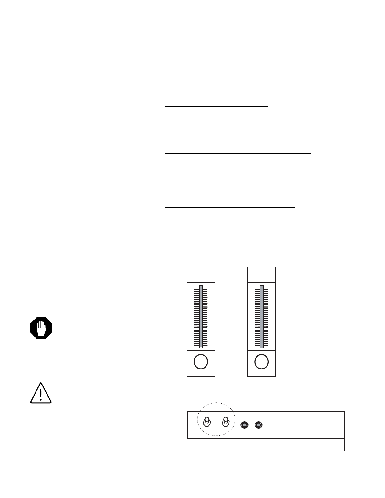
Air and CO2 (or Nitrogen)
The incubator is designed to be used with air and CO2 or
nitrogen only. Do not use any other gases. Each of the two
gas circuits has its own flow control. Air and CO2 flow
meters should be turned fully clockwise (shown below). Make
connections at the top of the unit at the air and CO2 inlets.
16
OPERATION
Control Panel Flow Meters
Rear/Top of Unit, Air and CO2 Inlets
Caution
Gas and air supplies must be
equipped with pressure-reducing
valves that are set at 15 psi. The
incubator is designed for a continu-
ous flow of gas, not for chamber
pressure.
Warning
High concentrations of carbon diox-
ide produce metabolic abnormali-
ties, disturbances of the central
nervous system and cardiac insta-
bility. Unconsciousness may occur
at concentrations above 10%.
Humidification
If the incubator is not to be humidified, keep the drain
valve (located on the bottom/rear outer panel) closed.
Humidifying without the Optional
Humidifier
Place a pan of distilled or deionized water on one of the
shelves to provide humidification. Run a hose from the
drainpipe at the bottom/center rear of the unit to a floor
drain or a pan. The drain petcock should be open.
Alternatively, moisture can be sponged up from the bot-
tom of the unit.
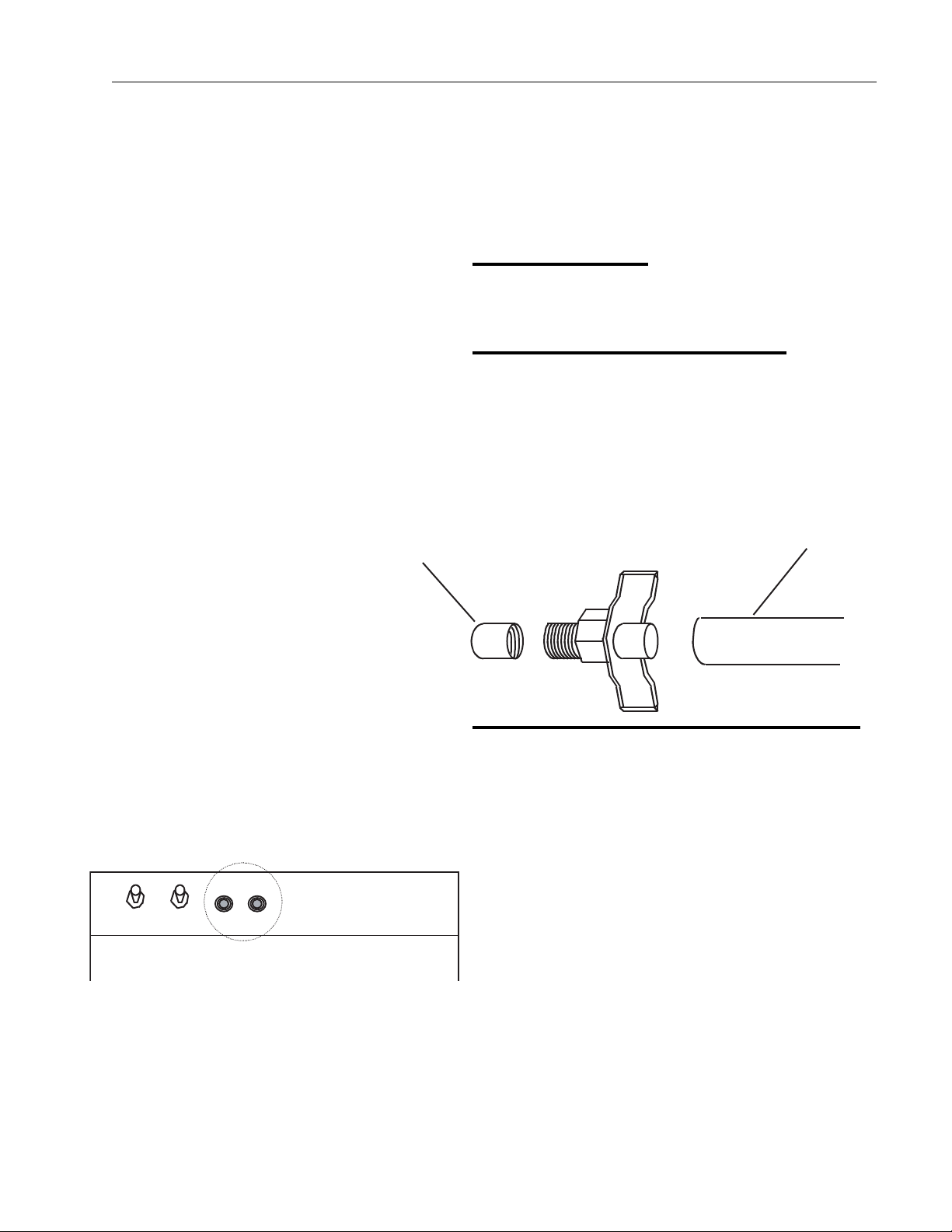
Humidifying with the Optional Humidifier
1. Humidity is produced by a humidifier located on
the roof of the unit.
2. The water inlet and outlet are on the rear panel
of the incubator (see figure at left).
3. Only demineralized or deionized water should
be used.
4. On the left side of the incubator is a rack for a
deionizer cartridge that can be connected as
shown in the deionizer diagram. Be sure to
connect a drain hose to the unit's drain pipe and
open the drain petcock.
17
OPERATION
Incubator Drain Pipe
Hose
Petcock for Drain
Rear/Top of Unit, Water Inlet/Outlet

About the Kind of Water to Use
Distilled or deionized water MUST BE USED for humidifi-
er(s). ELECTRICAL RESISTIVITY OF THE DISTILLED
OR DEIONIZED WATER MUST BE BETWEEN 500 K
OHMS AND I MEG OHMS as measured between oppo-
site faces of a centimeter cube of an aqueous solution as
per ASTMD 1125-82. Distilled water, if available, will give
the best results and the longest life expectancy for the
equipment. All DI and/or city water final connects shall be
by others. Due to the great variations in water hardness
and chemical makeup from one geographical area to
another, demineralizer cartridges may not, in all cases, be
adequate to prevent damage to the internal wetted parts
of the humidifier(s).
Purchasers are responsible for determining, through
water analysis and recommendations by a qualified water
treatment company, if further treatment is required, either
before, after, or in place of using a demineralizer car-
tridge. If further water treatment is necessary or advis-
able, the user is obligated to supply and install all equip-
ment that might be required for this purpose.
18
OPERATION
Caution
Distilled water shall be provided by
others at a minimum rate of 18 gal-
lons per day and a minimum pres-
sure of 20 psig with an electrical
resistivity between 500 K ohms
and I meg ohms.
Note
Barnstead International expressly
disclaims liability for damage to
humidifier(s) and for loss sustained
by the user as a result of humidifier
failure, if such damage is the result
of improper treatment of water used
for humidification.

Demineralizer Cartridge
19
123
4
5
6
7
8
9
10
11
1. Water Outlet – To Chamber
2. D. I. Cartridge, #585-036-00
3. D. I. Cartridge Housing, #019-153-01
4. Regulator Bracket, #593-798-00
5. 1/4” NPT water inlet fitting, supplied by user
6. Plastic Regulator, #950-147-01
7. PSI Gauge, #950-147-02, Set for 10 to 15 psi
8. Connector, #730-414-01, Regulator Outlet
9. Tubing, #720-113-00
10. Quick Disconnect, #731-093-00
11. 90° Fitting, #730-501-01
OPERATION

Operation of Humidification System
1. Water pressure is not to exceed 20 pounds per
square inch. The recommended water pressure
setting is 10 to 15 psi.
2. Water temperature should be regulated to 77°F
(25°C) for optimal cartridge usage.
3. Do not store in an area where temperature will
be below 33ºF or above 100ºF.
4. When mounting cartridge in bracket, tighten nut
moderately tight and turn on water. If leak
occurs, tighten nut until leak is stopped.
5. To obtain optimum performance from the dem-
ineralizer cartridge, it is important to check the
color change that the resin undergoes. When
the color of the resin in the cartridge has
changed from brown to tan, the cartridge should
be replaced. Preferably, cartridge replacement
should be done before the entire cylinder has
changed color.
Periodic Cleaning and Inspecting of
Humidifier
1. Disconnect power source from unit. Turn off
water supply.
2. Remove dome from unit after first removing the
dome strap. The dome rests on the chromed
motor pan. It lifts out and away from the duct
and the unit. Tube seal is on the dome dis-
charge exhaust and will be carried with the
dome.
3. Lift out the atomizing unit—this rests freely on
the reservoir and lifts out easily.
4. Clean the atomizing unit. DO NOT SUBMERSE
IN WATER. First, remove the cylindrical
screen—twist slightly out of the LOCK position
and remove. Next, remove the impeller cap
from the pump tube by tapping lightly against
20
Caution
FAILURE TO CHANGE THE DEM-
INERALIZER CARTRIDGE AS
REQUIRED CAN RESULT IN DAM-
AGE TO THE HUMIDIFIER AND
AFFECT IT’S PERFORMANCE, EFFI-
CIENCY AND VOID THE MANUFAC-
TURER’S WARRANTY.
OPERATION
This manual suits for next models
2
Table of contents


