BIANCHI VENDING BVM971 User manual

BVM971 - BVM951
CERT. N° 9105 BNVD
UNI EN ISO 9001: 2000
USE AND MAINTENANCE MANUAL


Mariella Trapletti
Zingonia (BG) - Italy
07/2004
Legal Rapresentative
DECLARATION OF EEC CONFORMITY
Bianchi Vending S.p.A. - situated in via Parigi n°5, Zingonia (Bergamo) Italy, represented by Mariella Trapletti - states that the
vending machines model:
“BVM971-BVM951”
are in conformity with the safety measures provided for by the Law nr. 98/37/EEC dated 22-06-1998 in its items n.1-2-3-4 and
relative enclosures 1-2-3-5 “Safety and Health and subsequent, and 73/23/CEE and subsequent.
Bianchi Vending S.p.A. has applied the Standards for the prevention and the elimination of the radio disturbances in respect of the
EEC Standards 89/336, 93/ 68 and subsequent annexes and of the D.L. nr. 476 and subsequent annexes , that are in conformity
with the norms EN 55014 3a ed., EN 55104, ENV 50141 and EN 61000.
The Standards used for testing of the suitability for contact with food substances are in accordance with DM 21-03-1973 Stan-
dards and subsequent annexes.
In general the rules of the Standards 90/128/EEC ,73/23/CEE and 89/336/CEE and subsequent annexes have been applied. The
Standards used for the safety tests on electrical parts are in accordance, ref. IEC 335-1 and subsequent.


BIANCHI VENDING S.p.A. - Viale Parigi, 5-7-9
24040 ZINGONIA DI VERDELLINO (BG) - ITALIA
Tel. 035 88 22 25 (ra) - Fax 035 88 33 04
BVM971 - BVM951

6
PE
SAFETY SYMBOLS
ATTENTION: Important safety indications
READ the instruction manual machine carefully before using the machine
For any service or maintenance switch off the machine
ATTENTION: machine switched on
ATTENTION: hot parts in contact!
CAUTION! Parts in motion
Earthing indication
Important notices
MAINTENANCE TECHNICIAN
The maintenance technician is defined as being the person responsible for filling up the containers with
soluble products, sugar, coffee, stirrers and cups.
The maintenance technician is also responsible for cleaning the distributor (see operations indicated in
chapter 7.0). In the event of a fault the maintenance technician must call the installation technician.
INSTALLATION TECHNICIAN
The installation technician is defined as the person responsible for the installation of the automatic distri-
butor, the starting up operations and the function settings.
Each regulation operation is the exclusive responsibility of the installation technician who also holds the
programming access password.
BEFORE USING THE MACHINE, READ THIS MANUAL CAREFULLY FOR ITS CORRECT USE IN AC-
CORDANCE WITH THE CURRENT safety STANDARDS.

7
Tools necessary for undertaking inter-
ventions on the automatic dispenser.
SOCKET SPANNERS
n° 5,5
n° 7
n° 8
n° 10
n° 20
n° 22
SPANNERS (fork type)
n° 7
n° 8
n° 10
n° 12
n° 14
SCREWDRIVERS
Small size
Medium size
Large size
Normal cross
Small cross
Medium cross
Large cross
Of Teflon, small size for Trimmer re-
gulation.
RATCHET SPANNER no.14
TESTER
ELECTRICIAN’S SCISSORS
PROGRAMMING KIT
Keys at the disposal of the
MAINTENANCE and INSTALLA-
TION technicians
Keys at the disposal of the MAIN-
TENANCE and INSTALLATION
technicians
Service key

8
INDEX
PREMISE
IImportant notices for operator
II Important notices
III Safety rules
1.0 DESCRIPTION OF THE MACHINE’S
TECHNICAL CHARACTERISTICS
1.1 Models
1.2Technical characteristics
1.3 Knowing the distributor
1.4 Scheduled Use
2.0 TECHNICAL DESCRIPTION OF THE
OPERATION
2.1 Basic principle of operation
2.1.1 for Mod. BVM971 – BVM951
2.1.2 for Mod. BVM971 – BVM951
3.0 TRANSPORTING THE AUTOMATIC
VENDING MACHINE
3.1 Moving and Transport
3.2 Stocking
3.3 Packing
3.4 Reception
3.5 Unpacking
4.0 INSTALLATION
4.1 Positioning
4.2 Water supply connection
4.3 Power supply connection
4.4 Machine starting up
4.5 Installation
4.5.1 Decalcificator resin washing where it is
installed as accessory
4.5.2 Filling of water circuit
4.5.3 Filling the cooling unit
4.5.4 Cleaning of parts in contact with food
substances
4.5.5 Payment system installation
4.6 Product loading
4.4.1 Product container loading
4.4.2 Label application
4.4.3 Cup loading
4.4.4 Spoon loading
4.4.5 Spent coffee grounds bag insertion
5.0 SOFTWARE INSTRUCTIONS
5.1 Programming menu
5.1.1 Menu “Options”
5.1.2 Menu “Temperature”
5.1.3 Menu “Preselections”
5.1.4 Menu “Unique Products”
5.1.5 Menu “Doses”
5.1.6 Menu “Times and thresholds”
5.1.7 Menu “Payment system”
5.1.7.1 Coins/Line
5.1.7.2 Bill/Line
5.1.7.3 Enable Coin
5.1.7.4 Enable bills
5.1.8 Menu ‘Price Table’
5.1.9 Menu ‘Price-Selection’
5.1.10 Menu ‘Table discounts’
5.1.11 Menu ‘Promotions’
5.1.12 Menu ‘Preventive action’
5.1.13 Menu ‘Decounter and Reserves’
5.1.14 Menu ‘Sales’
5.1.14.1 ‘System audit’
5.1.15 Menu ‘Clock’
5.1.15.1 ‘Hour/minute’
5.1.15.2 ‘Data’
5.1.15.3 ‘Switch on’
5.1.15.4 ‘Cleanings’
5.1.15.5 ‘Disinfection’
5.1.16 Menu ‘Test’ (under Password)
5.1.17 Default data
5.1.18 Menu ‘Item Number Cold’
5.2 Maintenance
6.0 MAINTENANCE AND INACTIVITY
6.1 Cleaning and loading procedures
6.1.1 Periodic cleaning by the maintenance
technician
6.1.2 Daily cleaning procedures
6.1.3 Product Loading instructions
6.2 Ordinary and Extraordinary Maintenance
6.3 Maintenance procedures
6.3.1 Sanitization
6.4 Regulations
6.4.1 Dosage and grinding regulation
6.4.2 Instant electrovalve water flow regulation
6.5 Resing regeneration (optional)
6.6 Neon light replacement
6.6.1 Mod. BVM971-BVM951
6.7 Inactivity
7.0 TROUBLESHOOTING GUIDE FOR THE
FAILURES OR MOST COMMON ERRORS
7.1 Alarms
7.1.1 Displayed blocking alarms
7.1.2 Alarms displayed under maintenance
7.1.2.1 Stored alarms
7.1.2.2 Unstored alarms
7.1.2.3 Stored signallings
7.1.3 BVM600 power card alarms
7.1.3.1 Stored signallings
8.0 DISMANTLEMENT
9.0 ACCESSORIES
9.1 Mod. BVM971
9.2 Mod. BVM951

9
FIG.1.1
PREMISE
I Important notices for operator
This automatic distributor has been designed and constructed in
full accordance with current safety regulations and is therefore safe
for those who follow the ordinary filling and cleaning instructions
as indicated in this manual.
The user must not under any circumstances remove the
guards that require a tool for removal.
Some maintenance operations (to be done solely by specialized
technicians and indicated in this manual with a special symbol)
require that specific safety protections of the machine must be
switched off .
In accordance with the current safety regulations, certain opera-
tions are the exclusive responsibility of the installation technician,
and the ordinary maintenance technician may have access to
specific operations on with specific authorization.
The acquaintance and absolute respect, from a technical point of
view, of the safety instructions and of the danger notices contained
in this manual, are fundamental for the execution, in conditions
of minimum risk, for the installation, use and maintenance of
this machine.
II General Instructions
Knowledge of the information and instructions
contained in the present manual is essential for
a correct use of the automatic vending machine
on the part of the user .
– Interventions by the user on the automatic vending machine
are allowed only if they are of his competence and if he has
been duly trained.
The installation technician must be fully acquainted with all
the mechanisms necessary for the correct operation of the
machine.
– It is the buyer’s responsibility to ascertain that the users have
been trained and are informed and regulations indicated in the
technical documentation supplied.
Despite the full observance of the safety regulations by the
constructor, those who operate on the automatic dispensers
must be fully aware of the potential risks involved in operations
on the machine.
– This manual is an integral part of the equipment and as such
must always remain inside of the same, so as to allow further
consultations on the part of the various operators, until the
dismantlement and/or scrapping of the machine.
– In case of loss or damage of the present manual it is possible
receive a new copy making application to the manufacturer,
with prior indication of the data registered on machines’ serial
number.
– The functional reliability and optimization of machine’s ser-
vices are guaranteed only if original parts are used.
– Modifications to the machine not previously agreed on with
the construction company and undertaken by the installation
technician and/or manager, are considered to be under his
entire responsibility.
All the operations necessary to maintain the machine’s effi-
ciency, before and during it’s use are at the users charge.
– Any manipulations or modifications made to the machine that
are not previously authorized by the manufacturer, relieve
the latter from any responsibility for damages deriving from,
and will automatically result in the cancellation of the machine
guarantee terms.
– This manual reflects the status at the moment of the emission
of the automatic vending machine on the market; possible
modifications, upgrading, adaptments that are done the ma-
chine and that are subsequently commercialized do not oblige
BIANCHI VENDING Spa neither to intervene on the machine
previously supplied, nor, neither to update the relative technical
documentation supplied together with the machine.
– It is however BIANCHI VENDING‘s faculty, when deemed
opportune and for valid motives, to adjourn the manuals already
present on the market, sending to their customers adjournment
sheets that must be kept in the original manual.
Possible technical problems that could occur are easily resolvable
consulting this manual ; For further information, contact the di-
stributor from whom the machine has been purchased, or contact
Bianchi Vending’s Technical Service at the following numbers:
When calling it is advisable to be able to give the following infor-
mation:
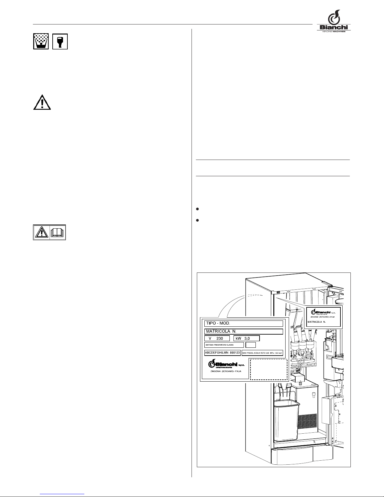
The data registered on the serial number label (Fig.1.1)
version of program contained in the microprocessor (Adhesive
label on the component installed on board).
035 4196711 - fax 02 70048332

10
BIANCHI VENDING Spa declines any responsibility for damages
caused to people or belongings in consequence to:
Incorrect installation
Inappropriate electrical and/or water connection.
Inadequate cleaning and maintenance
Not authorized modifications
Improper use of the distributor
Not original spare parts
– Under no circumstances is Bianchi Vending Spa obliged to
compensate for eventual damage resulting from the forced
suspension of drink deliveries as the result of faults.
– Installation and maintenance operations , must be done exclu-
sively by qualified technical personnel with prior training for
carrying out these duties.
– For refilling use only food products that are specific for auto-
matic vending machines.
– The automatic distributor is not suitable for external installation.
The machine must be installed in dry places, with temperatures
that never go below 1°C it must not be installed in places where
cleaning is done with water hoses (ex. big kitchens.).
Do not use water jets to clean the machine.
III - SAFETY NORMS
ATTENTION!
– before using the automatic distributor, read this manual care-
fully.
– The installation and maintenance operations must be performed
exclusively by qualified technical personnel.
– The user must not in any circumstance be able accede to those
parts of the automatic distributor that are protected and require
a tool in order to be accessible.
– The knowledge and the absolute respect, from a technical point
of view of the safety instructions and of the danger notices con-
tained in this manual, constitute the basis for the operation ,
in conditions of minimum risk, of the installation, starting and
maintenance of the machine.
Always disconnect the POWER CABLE before main-
tenance or cleaning interventions.
ABSOLUTELY DO NOT INTERVENE ON THE MACHINE AND
DO NOT REMOVE ANY PROTECTION BEFORE THE COOLING
OF THE HOT PARTS!
– The functional reliability and optimization of machine’s ser-
vices are guaranteed only if original parts are used.
– In order to guarantee normal operation, the machine must be
installed in areas that the environmental temperature is between
a minimum of +1°C and a maximum of +50°C end humidity of
not over 85%.
– In order to guarantee a regular operation, always maintain the
automatic distributor in perfect cleaning conditions
– If at the moment of the installation, if conditions differing from
those indicated in the present manual, or should the same un-
dergo changes in time, the manufacturer must be immediately
contacted before use of the machine.
– Also check that any other eventual norms or regulations as laid
down by national or local legislation are taken into account and
applied.

11
Fig. 2.1
1.2 Technical Characteristics
BVM971 BVM951
Height (A) 1830 mm 1630 mm
Width (B) 657 mm 585 mm
Depth (C) 730 mm 649 mm
Weight 140 kg÷190 kg (3) 110 kg
Power Supply V230 V230 – V120
Power frequency Hz 50 Hz 50 ÷ Hz 60
Installed power (1) 1,8 kW ÷ 3,2 kW 1,8 kW ÷ 2,7 kW
Nominal current (Max) 8 A - 15 A 6 A – 12 A
Water supply 0,5 ÷ 6,5 bar 0,5 ÷ 6,5 bar
AVERAGE CONSUMPTIONS:
Keeping T° /24h 1400 W/h-2400W7h 1400 W/h-2100W7h
For 60 supplies / min 90 W/h-170W/h 90 W/h-140W/h
Water supply connection 3/8” gas 3/8” gas
Electrical supplY connec. Schuko plug Schuko plug
CUPS DISPENSER
Caps diameter 70÷74mm 70÷74mm
BOILER RESISTANCES
of armoured type: coffee boiler: 1500W coffee boiler:
1500W
of armoured type: instant boiler: 2000W instant boiler:
1300W
PRODUCT CONTAINER CAPACITY
Coffee in beans Kg 5,0 Kg 3,5
Instant coffee Kg 1,4 Kg 1,2
Powder milk Kg 2,2 Kg 1,7
Creamer Kg 4,0 Kg 3,2
Chocolate Kg 4,8 Kg 3,6
Tea Kg 5,2 Kg 3,3
Frozen-dry tea Kg 2,4 Kg 1,7
Broth Kg 3,8 Kg 3,6
Instant cold beverages Kg 4,0 -
Sugar Kg 4,0 Kg 4,0
Caps N° 700 500
Spoons N° 540 400
cooling unit (2) Class N Class N
cooling gas R134a – Peso 180gr R134a – Peso
180gr
Type of light and power N° 1 Neon light
8 Watt
N° 1 Neon light
8 Watt
(2) According to the requested version and the applicable standards in
the place of use.
(1) Check the rated output indicated on the data plate applied by the
distributor.
(3) According to the version.
1.0 GENERAL TECHNICAL
1.1 Models
The following terminology is used so as to distinguish the various
models of automatic distributors:
BVM971 E (version with espresso coffee and instant
beverages)
BVM971 I (version with instant beverages)
BVM951 E (version with espresso coffee and instant
beverages)
BVM951 E/H&C (version with espresso coffee and instant
hot and cold beverages)
BVM951 I (version with instant beverages)
BVM951 I/H&C (version with instant hot and cold beve-
rages)
N.B.: after the lettering Eand Ian Fcan follow in order to
countersign the machines equipped with cooling unit class N.
The manual is compiled for the most complete model: it is
therefore possible, to find descriptions or explanations not
related to your machine.

12
Fig. 2.1
1.3 KNOWING THE DISTRIBUTOR
Mod. BVM971-BVM951
1Coffee group and grinder
2Drink dispensing group
3 Sugar dispenser group
4Cooling unit (optional – mod.BVM971 – BVM951)
5Cup column
6Electronics board
7Spoons column
8Water softener filter (optional)
9Water bin
10 Payment system
1.4 Foreseen use
The automatic distributor is exclusively for the dispensing of drinks,
prepared mixing food substances with water (by infusion as far
as concerns espresso coffee).
For this purpose use products declared as suitable by the manu-
facturer for automatic distribution in open containers. The drinks
are made in specific plastic cups automatically dispensed by the
machine. Where foreseen, also the spoon for mixing the sugar is
dispensed.
The drinks must be consumed immediately and in no case are to
be kept for subsequent consumption.

13
Fig. 2.2
Fig. 2.3
Fig. 2.4
2.0 TECHNICAL DESCRIPTION OF THE OPERA-
TION
During the normal functioning the distributor is set in standby
status.
Introducing the necessary amount, according to the set price,
and after pressing the key relative to the desired drink, the drink
dispensing cycle is activated and can be divided in to different
processes:
2.1 BASIC PRINCIPLE OF OPERATION
2.1.1 For MOD. BVM971 – BVM951
CUP DISPENSING
– It is the first operation that the distributor starts (except for
the selections with pre-selection “without CUP”).
– the motor inside of the cup dispenser moves the plastic gear
to separate and make the cup fall into the cup ring inside the
cup dispenser (Fig.2.2).
2.1.2 For MOD. BVM971 – BVM951
SUGAR DISPENSER
The sugar is dispensed directly in the cup in the E versions whereas
for the I versions it is pre-mixed with the instant drinks.
The display management of the presentation INC+ / DEC- Sugar,
is represented this way:
Line 1: Sugar
Line 2:
Each square is equivalent to x sec of sugar according to the fol-
lowing equation
= (A+B)/8
A = Quantity in seconds of sugar in the standard drink
B = Quantity in seconds of sugar in the preselection +
8 = Maximum number of squares
The dispensing procedure occurs according to the following pha-
ses:
- the geared motor activates the helicoidal screw conveyor of the
sugar product container, dispensing the desired quantity into
the product chutes (Fig.2.3)
- The geared motor is activated (mod. BVM971 only) and by
means of the cam, it effects the movement of the product chute,
in order to make sugar to fall into the cup (Fig. 2.4).

14
Fig. 2.6
Fig. 2.5
Fig. 2.8
Fig. 2.7
Fig. 2.9
ESPRESSO COFFEE
This process functions only the models equipped with the coffee
espresso group (brass or plastic), after the cup and sugar dispen-
sing processes have been effected.
– the grinder is activated until it reaches the dose of ground coffee
set by the doser (Fig.2.5)
– the doser electromagnet is activated , causing the opening of the
door and consequent fall of the coffee into the brew chamber
– the rotation group geared motor brings it into the dispensing
position and simultaneously compresses the ground coffee
(Fig.2.6).
– the pump that dispenses the quantity of programmed water
and that is controlled by a specific electronic device, (volume
meter), extracting the water from the coffee boiler(Fig.2.7).
– the coffee group geared motor is activated again so as to bring
again into standby position ; during this movement the used
coffee grounds are expelled (Fig.2.8)
The sequence of these operations (grinding and coffee dispensing)
could occur in inverse order according to the type of programme
used.
COOL SOUP DRINKS
This process, similar to the preparation of hot drinks, except for
water supply which is drawn from the activation of an electrovalve
located on the refrigerating group, is activated only in versions
fitted with refrigerating group (Fig. 2.9).

15
Fig. 2.10
Fig. 2.13
Fig. 2.11 Fig. 2.12
Fig. 2.14
SPOON DISPENSING
This process is activated only in the versions where the spoon
dispenser is foreseen; In these versions it is possible to select
the spoon in the selections without sugar and/ or in the instant
selections . In the Imodels the spoon dispenser is not foreseen
as the sugar comes pre-mixed with the instant beverages.
- the geared motor that operates the spoon release device is
activated making the spoon fall into the cup. (Fig.2.10).
INSTANT DRINKS
This process is activated when the cup and spoon dispensing
processes have been completed.
According to the type drink requested and to the distributor mo-
del, several of the various processes described here below can
be activated.
– If present, the whipper motor is activated (Fig.2.11)
- The electro valve fixed on the soup boiler (Fig.2.12) or on the
coffee boiler (Fig.2.13). it is activated to introduce into the
mixer the programmed water quantity, according to the models:
Single boiler, Double boiler or only Istant.
- The instant product geared motor activates the helicoidal screw conveyor so as to dispense the quantity of product programmed into
the mixer (in some versions several products can be processed in the same mixer such as milk and chocolate)
- Once the preset water and powder quantity has been preset has been supplied, the mixer is disabled after a time (T) set during the
programming.

16
Fig. 3.1
Fig. 3.2 Fig. 3.3
Fig. 3.4
190 kg
3.0 MOVING AN AUTOMATIC VENDING
MACHINE
3.1 Moving and transport (Fig.3.1)
The transport of the distributor must be effected by competent
personnel.
The distributor is delivered on a pallet; for the shifting use a trol-
ley and move it slowly in order to avoid capsizing or dangerous
movements.
Avoid :
– lifting the distributor with ropes or presses
– dragging the distributor
– upset or lay down the distributor during transport
– give jolts to the distributor
Avoid as the distributor:
– bumping it
– overloading it with other packages
– exposing it to rain, to cold or sources of heat
– keeping it in damp places
The construction company is not liable for any damage which
may be caused for the partial or complete non-observance of the
warning notices indicated above.
3.2 Stocking
For eventual stocking, avoid laying several machines over each
other, maintain it in vertical position, in dry places with tempera-
tures not inferior to 1°C (Fig.3.2).
3.3 Packing
The distributor is protected with polystyrene angles and by a
transparent film in polypropylene (Fig.3.2).
The automatic distributor will be delivered packed, assuring both
a mechanical protection and protection against damages from
the external environment.
On the package labels are applied indicating:
maneouver with care
don’t turn upside-down
protect from the rain
don’t superimpose
protect from sources of heat
not resistant against bumps
type of distributor and serial number.
3.4 Reception
Upon reception of the automatic distributor you need to check that
the same has not suffered damages during the transport.
If damages of any nature are noticed place a claim with the
forwarder immediately.
At the end of the transport the packing must result without
damages which means it must not :
– present dents, signs of bumps, deformations or damages of the
external packaging
– present wet zones or signs that could lead to suppose that the
packing has been exposed to rain, cold or heat.
– present signs of tampering
3.5 Unpacking
- Free the distributor from the packaging , cutting the protective
film in which it is wrapped, along one of the protection angles
(Fig.3.3).
- Remove the distributor from transport pallet, unscrewing the
screws (A) that block the fixing cross staff heads to the pallet
(Fig.3.4).

17
Fig. 3.6
Fig. 3.7 Fig. 3.8
Fig. 3.5
– Release the pallet and insert the 4 feet into the threaded slots
(fig. 3.5) freed of the screws (A)
– remove the key from the drink dispensing chamber (Fig.3.6)
Open the door of the distributor and remove the adhesive tape
from the components listed here below:
cup turret (example in Fig.3.7)
coin box
sugar container
weight on the spoon dispenser column
coin mechanism cover / Master board
product containers
water bin float mechanism (BVM971-BVM951)
bottom skirting-board (BVM971-BVM951)
water bin (BVM971-BVM951)
remove the polystyrene that that blocks the product containers
(Fig.3.8)
The packing material must not be left accessible to others,
as it is a potential environmental pollution sources. For
the disposal contact qualified companies authorized.

18
Fig. 4.5 Fig. 4.6
Fig. 4.3 Fig. 4.4
Fig. 4.2
Fig. 4.1
4.0 INSTALLATION
4.1 Positioning
– If positioned near to a wall, there must be a minimum distance
from the wall of at least 5 cm. (Fig.4.1) so as to allow a regu-
lar ventilation. In no case cover the distributor with cloths or
similar.
– Position the distributor, checking the leveling by means of the
adjustable feet already assembled on the machines (Fig4.2).
make sure that the distributor doesn’t have an inclination of
more than 2 degrees.
WARNING! Do not position the device near inflammable
objects, keep a minimum safety distance of 30 cm.
Bianchi Vending Spa declines all responsibility for inconveniences
due to the non observance of the above mentioned installation
norms.
If the installation is made in safety evacuation corridors make
sure that with the distributor door open there is anyhow sufficient
space to pass by (Fig.4.1).
So as to avoid that the floor gets dirty, due to accidental spilling of
the products, use, if necessary, under the distributor, a protection
sufficiently wide to cover the distributors’ operating space.
6.2 Connection to the main water supply
Before proceeding with the connection of the distributor
to the water main supply verify the following water cha-
racteristics:
– that it is drinkable (eventually through an laboratory’s analysis
certification)
– it has a pressure comprised between 0.5 and 6.5 (bar) ( if this
should not be the case, use a pump or a water pressure, reducer
according to the case).
– install, if not present, a tap in an accessible position to isolate
the machine from the water mains should it be found to be
necessary (Fig.4.3).
– before making water connections, make some water flow out
of the tap so as to eliminate possible traces of impurities and
dirt (Fig.4.4)
– connect the cock to the distributor, using a pipe in nylon material
suitable for food products and suitable for the mains pressure.
In the event of the use of a flexible pipe it is necessary to fit
the reinforcement bush supplied inside (Fig. 4.5).
– the foreseen connection is a 3/ 8 gas (Fig.4.6).

19
OK
Fig. 4.7
NO
Fig. 4.8
4.3 Main Power supply connection
The distributor is predisposed to function with mono-phase 230
Volt tension and is protected with 12,5A and 20A fuses. (10A and
20A for the single boiler and instant versions and 15A and 20A for
the instant hot/cold version).
We suggest to check that:
– the tension of net of 230 V doesn’t have a difference of more
than ± 6%
– The power supply output is able to bear the power load of the
machine.
– use a system of diversified protection
– position the machine in such a way as to ensure that the plug
remains accessible
The machine must be connected to earth in observance with the
current safety norms.
For this reason, verify the plant’s earth wire connection to ascertain
that it is efficient and it answers national and European safety
electric standards. If necessary require the intervention qualified
personnel for the verification of the plant.
– The distributor is equipped with a power supply cable of H05VV-
F 3x1,5mm², with SCHUKO plug (Fig.4.7).
– The sockets that are not compatible with that of the machine
must be replaced. (Fig.4.8).
– The use of extension, adapters and/ or multiple plugs is forbid-
den.
– In some models, specific plugs are assembled for the destination
place.
Bianchi Vending S.p.A. declines all responsibility for damages
deriving for the complete or partial failure to observe these war-
nings.
Should the power cable be found to be damaged, immediately
disconnect from the power socket.
The power supply cables are to be replaced by skil-
led personnel.

20
1
Fig. 4.9
Fig. 4.10
Fig. 4.11 Fig. 4.12
4.4 Starting up of the unit
The distributor is equipped with a safety switch (Fig.4.9) that di-
sconnects the machine whenever the door is opened ( see electric
schema).
In case of necessity, therefore, open the door or disconnect unplug-
ging of the machine from the power supply.
The clamp of the power cable junction box remain
under tension (Fig.4.10-pos.1) as well as the servi-
ce switch inside the distributor. (Fig.4.11-pos.1).
– For some operations is however necessary operate with the
door open but with the distributor connected.
It is possible for installation technician, to operate in this way,
by inserting the special plastic key, supplied with the distributor,
into the door switch and rotating it 90° (Fig.4.12).
The opening and the possible connection with the distri-
butor’s door open must be performed only by authorized
in carrying out these operations.
Don’t leave the distributor open and unguarded.
Give the key only to qualified personnel.
Any time the distributor is switched on there is a diagnosis cycle
to check the state of DA peripherals and perform the restoration
of moving parts.
This manual suits for next models
1
Table of contents
Other BIANCHI VENDING Beverage Dispenser manuals
Popular Beverage Dispenser manuals by other brands

Bunn
Bunn CDS-2 OPERATING & SERVICE MANUAL

Cecilware
Cecilware Radiance 5A manual

Cornelius
Cornelius Cornelius VANTAGE POST-MIX DISPENSER Service maintenance manual

Wilshire
Wilshire SLJ 1000-1 Installation and service manual

Cornelius
Cornelius FCB Cord Kit installation instructions

Stoelting
Stoelting CBD117 Operator's manual

Grindmaster
Grindmaster CP3 Service manual

Cornelius
Cornelius 326142000 Service manual

Hoshizaki
Hoshizaki DBF-40WAC instruction manual

Ugolini
Ugolini A 12 Operator's manual

Cornelius
Cornelius SPIRIT 414384-XXX Illustrated parts list

Fisher & Paykel
Fisher & Paykel DCS RF24BTL1 Installation, operation and maintenance instructions