biawar Kaskada 2 Specification sheet

OP-12/18/21/24.04
01.03.2016
Operating and Installation Manual
3-phase electric
instantaneous water heater
Kaskada 2

Instantaneous water heater
OP-xx.04
2
INSTALLATION AND OPERATING MANUAL
CONTENT
1. GENERAL ..................................................... 3
1.1 Introducon................................................................3
1.2 Intended Use ..............................................................3
1.3 Contact .......................................................................3
.............................. 3
............................. 3
3.1 Hydraulic installaon ..................................................3
3.2 Electrical Connecons ................................................4
.............................. 4
...................................................... 4
............................. 5
6.1 Venng the heater......................................................5
6.2 Draining the Instantaneous Water Heater..................5
............................................... 5
... 5
.................................................. 6
......................................... 6
....................................................... 6
12. R ............................... 6
............................................ 7
............................................................ 8
The Manual includes installaon diagrams that don’t replace the system design and can be used only for illustrave purposes.
The product is not intended for use by persons with reduced physical tness/mental eciency or without experience and knowledge, if they are
not supervised or instructed by a person responsible for their safety. Operaon of the product by children is strictly prohibited.
We reserve the right to make product design changes and changes in the manual.
©NIBE-BIAWAR 2016

3
INSTALLATION AND OPERATING MANUAL
Instantaneous water heater
OP-xx.04
• Do not connect the pre-heated water (above 20 °C)
• Use of a gasket with a strainer (included) in the wa-
ter connecon is mandatory
• Wash and vent the water system
• The water system supplying the heater should be
separated from other devices that could cause un-
controlled addional movement of the water or ae-
raon of the system
• Use pipes of heat resistance min 95 °C (we recom-
mend using metal pipes), at a distance of min 3 m
at the heater inlet
• At the hot water discharge from the heater only
install pipes with heat resistance min 95 °C (we re-
commend using metal pipes)
1. GENERAL
The heater is designed to quickly heat water for sanitaon
purposes. It can be installed wherever there is the water and
electricity supply (3-phase power supply is required). You
can supply several water intake points at the same me. The
heater is economical to use, since its energy consumpon
(the number of heaters switched ON) adjusts automacally
to the amount of water consumed and the set temperature.
The heater can be installed in any room, in which the am-
bient temperature does not fall below 0 °C. The heater is a
pressure device, i.e. the pressure in the heated tank corre-
sponds to the pressure in the domesc water system.
In order to avoid heat loss, we recommend to:
• install the heater closest to the most common wa-
ter intake locaon
• insulate the hot water piping
Do not use glue for a aching, , because bonding is
not considered a reliable method of a aching.
Vent the heater before using it.
Vent the heater by complete opening the tap (with the pow-
er switched OFF) unl a steady stream of water ows out at
the intake point.
• Connect the heater to the water supply system with
a pressure of 2 to 6 bar. For pressures greater than
the rated, use a pressure reducer on the cold water
inlet. The safety valve is not required.
Secons of the Manual relang to the installaon,
inspecon and maintenance are intended for the
qualied installer.
Thank you for your condence and choice of equipment by
BIAWAR. To fully benet from the advantages of this prod-
uct, please read this Manual before using it, and in par-
cular chapters relang to the applicaon, installaon and
maintenance, and warranty. Please keep this Manual in a
safe place for future reference.
We welcome any comments on the operaon of the heater.
Secons of the Manual relang to the installaon,
inspecon and maintenance are intended for the
qualied installer.
Informaon
Please read the manual thoroughly before you begin
installaon and operaon of the heater.
Electrical connecon may only be made by a person holding
a valid authorizaon to electrical installaon works. Check-
ing and rst start should only be carried out by an appropri-
ately qualied installer.
If you have any quesons or doubts, please contact us:
NIBE-BIAWAR sp. z o.o. reserve the right to make technical
changes of our products.
The resisvity of the tap water may not be less than
1300 Ωcm at 15 °C. You can obtain the informaon on
this value from your water supply company.

Instantaneous water heater
OP-xx.04
4
INSTALLATION AND OPERATING MANUAL
The heater is ready for operaon (voltage is present) from
the moment when the power is switched ON with the circuit
breaker, which is indicated by the LED. The water is heated
only when it ows through the tank with the heaters. Great-
er power is switched gradually with increasing water intake.
Depending on the range seng and the temperature of the
water in the system, warm or hot water is discharged. Se-
lecon of the appropriate operang range can be done on
the basis of the temperature of the heater feed water. Red
LED’s indicate at what power level the heater is currently
operang - (see Table 3)
The heater has the following protecon systems installed:
• a thermal switch disconnecng the heater from the
mains in the event of excessive temperature rise
• a release valve protecng it against overpressure
Electrical installaon, which will be connected to the
heater, should be done in accordance with applicable
regulaons.
Electrical installaon specicaons:
• The heater should be connected to the electrical instal-
laon in the TN-S or TN-C-S network system in accord-
ance with PN-IEC60364-3: 2000
• Connect with 4-conductor copper cable, 300/500 VAC,
with a min cross-secon area, according to , in-
troduced into the heater through the opening in its rear
panel – the heater must be permanently connected to
the mains.
• For the types of the heater protecon, see
• Connect the L1, L2 and L3 cables to the terminal strip,
to the L1, L2 and L3 terminals, respecvely
• Connect the PE cable to the PE terminal on the rear
panel (see Fig. 4)
• We recommend to install a in the heater
supply line in order to disconnect it from the mains
• The electrical installaon must be equipped with an
with a value of
For the wiring diagram of the heater, see Fig. 3
The heater must be connected to an eecve protec-
ve circuit. Protecve terminal of the heater must be
connected to the network protecve conductor and
this connecon has to be veried.
Lack of the RCCB may result in electric shock, dam-
age to equipment and re.
• Connect the heater to the water system ghtening
the nuts to the protruding nipples of the installa-
on pipes – always install the gaskets (gasket with
strainer in the water supply line). You can connect
the heater in an alternave way – you have to ob-
tain a ‘connecon assembly’ and connect the heat-
er to the system through the cut out in the boom
of its housing, using braided hoses (see Fig. 2). Be
sure to install a shut-o valve in the system supply-
ing the water to the device
• Tighten the screws that secure the heater – between
the edge of its rear panel and the plane of suspen-
sion, a clearance of approx. 2mm should be visible
• Check the ghtness of connecons, including the
water ow, remove any leaks, then vent the heater.
3. Connect the wires to the terminal block of the safety
switch:
• Connect the electronic system to the control PCB
in the cover
4. Place the cover:
• Place the cover from the boom and then push it
onto the wall. Screw in two self-tapping screws.
Set the potenometer with the notch up. Place the
knob and push it so that it snaps into the cover
5. Switch the power ON – the green LED should light up
• Set the knob in either of the posions (I or II)
• Open the water ow. More LED’s illuminate de-
pending on the ow rate
Follow the steps below to ensure correct installaon and
operaon of the device:
1. Remove the cover:
• Remove two self-tapping screws in the upper part
of the cover and remove it by lng the upper part
forward and pulling it down. Disconnect the cable
connecng the electronic system to the control
PCB xed to the cover
2. Mount the heater on the wall:
• Install dowels – selecon of holes to the suspen-
sion and the amount of dowels (3 or 4) depends
on the installer – you can use the boom of the
cardboard box with the spacing of the connecng
and assembly holes printed on it as a template;
• Insert the power cable at the point shown in Fig. 4;
• Fasten the heater using props (Fig. 5) – screw n-
ger ght only
Before placing the cover, ensure that the water feed
pipe is latched and secured on the fastening catch.

5
INSTALLATION AND OPERATING MANUAL
Instantaneous water heater
OP-xx.04
The green LED indicates that the heater is energized. Set the
knob in either of the posions (I or II). Aer opening the tap
(water ows through the heater), glowing red LED’s indicate
the amount of power depending on the set range (see Table
3). The water temperature at the heater outlet depends on the
inlet water temperature, ow rate and power switched ON.
In summer, when the water in the system has a temperature
of about 15 °C, we recommend the use of the range I.
In winter, when the temperature of the water in the system
drops below 10 °C, we recommend the use of the range II.
If the taken water is too hot, then:
• increase the water intake by opening the tap more
• select the heater operang range I.
If the taken water is not hot enough, then:
• decrease the water intake by closing the tap a lile bit
• select the heater operang range II
Do not set the knob in a posion between the operang
ranges. If there is no water in the system (i.e. air ows from
the tap), close the valve and switch the power OFF. Turn it
ON again aer cooling and venng the heater.
Vent the heater by complete opening the tap (with the pow-
er switched OFF) unl the water ows out. The heater can
operate at dierent pressures in the water supply system.
At a pressure of 6 bar, the amount of water owing through
the heater may be too high in relaon to the possibility of
heang it, which can be found at the max water consump-
on. You can adjust the amount of water taken with the tap.
You can also limit the maximum water ow using the control
valve installed in the water supply line to the heater – by
throling the water supply system. In the case the tempera-
ture of the room where the heater is installed is lower than
0 °C, it is essenal to drain the water from the heater and
switch OFF the supply voltage.
Drain the heater through the outlet aer disconnecng the
water supply to the heater and opening the tap. Due to the
design of the tank, the water is not able to escape from the
tank by gravity. Use the compressed air. The air should be
directed to the cold water inlet nozzle and blow the water
system, unl the water stops leaking from the tap.
Unplug the heater from the mains before you start
draining it.
Reducing the ow of water through the heater despite the full
opening of the tap, may be evidence of contaminaon of the
strainer, which should be installed in the water supply line.
Remove and clean the gasket with the strainer.
If it is excessively worn, replace the gasket with the strainer;
you can purchase it in our authorized Service Centres.
For the current list of the authorized Service Centres, see
our website, at www.biawar.com.pl.
Maintenance may only be carried out aer discon-
necng the unit from the power and with the water
supply closed.
• INSTALL the heater in a posion other than vercal
(i.e. with the pipes downwards)
• PULL the electrical cables of the heater
• REMOVE the cover when the heater is energized
• CONNECT the heater to the water system contain-
ing air pockets
Heaters are safe and reliable in operaon provided that you
observe the following rules:
• Make sure that the electrical installaon has a cor-
rect protecve circuit connected
• If electrical connecons should be made, this
should be done by a licensed electrician
• Wash the heater and the water supply system pip-
ing with water (without connecng the unit to the
mains) before using the heater
• Install the gasket with the strainer in the water
connecon (see secon 9 Accessories)
• Report any irregularies in the operaon of the
heater (e.g., it does not heat, steam gets out aer
opening the tap, etc.) immediately to an author-
ized service facility

Instantaneous water heater
OP-xx.04
6
INSTALLATION AND OPERATING MANUAL
• CONNECT to the mains via a plug and socket.
• SWITCHING the power ON without the water. Re-
start the heater aer venng it.
• CONNECT accessories other than those recom-
mended by the manufacturer
• INSTALL the heater in a room where it could be ex-
posed to freezing
• MAKE any unauthorized repairs
• THROTTLE the ow. Clean the aerator and the
showerhead pinholes on a regular basis
The set includes the following items:
• Heater 1 pce
• Gasket 1 pce
• Gasket with stainer 1 pce
• Knob 1 pce
• Screws with dowels 4 pce
• Props 4 pce
• User’s manual 1 pce
Opons:
Assembly for the boom connecon
Problem Cause Remedy
• ow rate too low
• insucient water supply pressure
• increase the ow of water
• clean the aerator or showerhead pinholes
• clean strainer in the heater inlet pipe
• open the inlet tap completely
• decrease the temperature setpoint by turning the
knob counterclockwise
• no supply
• ow too high
• check the power supply (the LED lights up)
• decrease the ow of water
• clogged strainer
• insucient water supply pressure
• clean strainer in the inlet pipe
• check the water pressure in the water supply system
If these steps do not improve operaon of the heater, call an
authorized service technician. The current list of authorized
services is available on our website www.biawar.com.pl.
The heater may only be repaired/serviced by qual-
ied service personnel, since improperly performed
repairs can be a cause of safety hazards.
Problems and remedies
Report any abnormality in the heater operaon to an au-
thorized service facility.
12. R
This symbol on the devices and / or accompa-
nying documents means that used electrical
and electronic products should not be dispo-
sed of with other waste. These products must
be returned to a designated waste collecon
facility, where they will be received at no char-
ge and subjected to processing (recycling).
According to the NIBE rules, product is manufactured from
materials and components of the highest quality, subject to
further processing (recycling).
Correct disposal of discarded equipment helps to conserve
natural resources and prevents any potenal adverse ef-
fects on human health and the environment, which could
increase due to improper storage of waste.
In order to prevent damage to piping systems and
environmental polluon, the product should be re-
moved and taken out of service by a person with ap-
propriate qualicaons.
At the end of product life cycle, take care to transfer it
together with all accessories to disposal in accordance
with applicable regulaons.
For informaon about points of disposal of used electrical
and electronic equipment, please contact your local autho-
rity representave, reseller or distributor.
The packaging in which the product is delivered is made
mainly from materials suitable for recycling and reuse.
Aer installaon of the unit, ensure the proper disposal
of packaging, in accordance with applicable regulaons.

7
INSTALLATION AND OPERATING MANUAL
Instantaneous water heater
OP-xx.04
A A A A
%39,7 39,5 39,5 39,5
XS XS XS XS
2,123 2,136 2,136 2,136
466,8 470 470 470
15 15 15 15
V400V 3~
12 18 21 24
4-6-6-10 6-9-9-15 7-11-11-18 8-12-12-20
4-6-8-12 6-9-12-18 7-11-14-21 8-12-16-24
A17.4 26.1 30.4 34.8
A3x20 3x32 3x35 3x40
24x2.5 4x4 4x6 4x6
6 6 6 6
2-6 2-6 2-6 2-6
C 5,4 8,1 9,5 10,8
C min. 1300 min. 1300 min. 1300 min. 1300
460x210x130
3,7
*-zgodnie z rozporzadzeniem komisji (UE) 812/2013, 814/2013
Power levels indicaon depending on the seng of heang range.
Technical data
Power level
indicaon heater power
voltage turned on
Power level
Instantaneous water heater
OP-xx.04
8
INSTALLATION AND OPERATING MANUAL
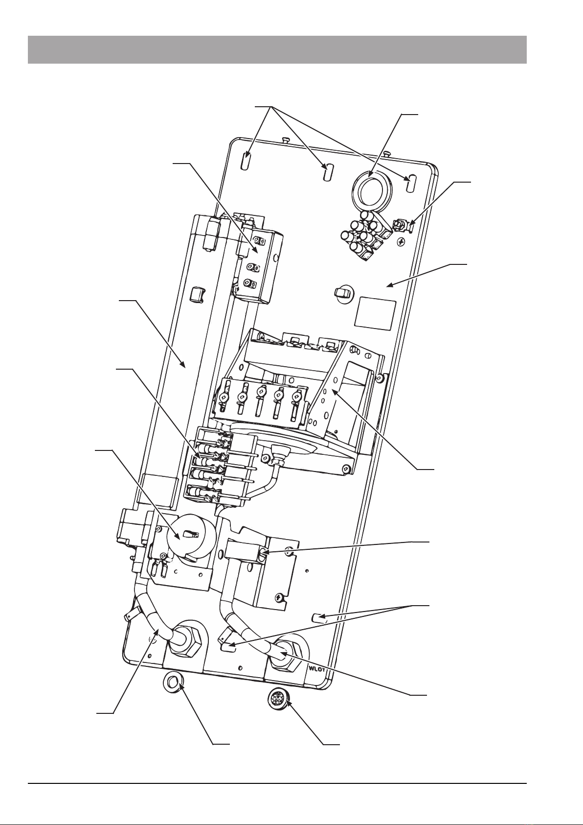
Construcon of the heater
holes to
suspend
thermal
switch
heang
tank
LED’s
range I & II
knob
water outlet
gasket gasket with
strainer
water inlet
hole to
suspend
drain (safety)
valve
ow switch
rear panel
PE terminal
opening for
inserng cables

9
INSTALLATION AND OPERATING MANUAL
Instantaneous water heater
OP-xx.04
L1
L2
L3
PE
PE
2’
1’ 4’
3’
2 1
43
5554535251
LS
LS
LS
LS
W1
Blok
mikrowyłączników
Wyłącznik
Termiczny
Złączka
Electrical connecon
opening for inserng
cables
PE terminal
preferably, bend the
protecve conductor p
terminal block
W1 range I, II
LS Warning lights
1, 2, 3, 4 Heater bases in the tank upper panel
1’, 2’, 3’, 4’ Heater bases in the tank lower panel
~2
Fixing to the wall
screw
prop
dowel
rear panel
Examples of connecon of the heater to the water supply system
connecng
assembly
hose
Wiring diagram of the heater
Thermal
switch
block of
microswitches
nipple

Instantaneous water heater
OP-xx.04
10
INSTALLATION AND OPERATING MANUAL


al. Jana Pawła II 57
15-703 Białystok
tel. 85 662 84 90,
fax 85 662 84 09
sekretariat@biawar.com.pl
www.biawar.com.pl
This manual suits for next models
4
Table of contents
Popular Water Heater manuals by other brands

A.O. Smith
A.O. Smith TJH Specification sheet

GE
GE GeoSpring GEH50DEEDSR Owner's Manual & Installation Instructions

Rheem
Rheem PVG Installation, operation and service manual

Bosch
Bosch TR6000R 18/21 ESOB operating manual

Webasto
Webasto thermotop C installation instructions

Nibe
Nibe UKV 200 Kyla User's and installer's manual

clage
clage CFX-U Installing instructions for the professional

A.O. Smith
A.O. Smith Water Heater user manual

Eternal
Eternal GU32DV Operator's manual

ACV
ACV WaterMaster 25 Evo Installation operation & maintenance

Bradford White
Bradford White M-1-40S6BN Installation and operating instruction manual

clage
clage ISX quick start guide


