BICOLD WBA Series User manual
1
USER INSTRUCTIONS
Air-cooled Water chillers WBA and
Heat Pump WHA
GENERAL TABLE OF CONTENTS
1.
CE model plate
Page
2
2. Safety notes
Page
2
1.
Symbols on the unit
Page 3
2.
User Manual
Page
4
BICOLD Srl - Arzergrande (PD) - ITALY
WBA CHILLER ________ USER MANUAL Release 110613

2
Safety notices for use of the unit
Read this Manual carefully before using the unit!
Keep the manual safe and ready for consultation for all future requirements!
ALWAYS PROVIDE CUT-OUTS SO THAT THE POWER FEEDING LINE OF THE
UNIT CAN BE DISCONNECTED FROM THE ELECTRICAL MAINS SUPPLY, EVEN IN THE
PRESENCE OF A UNIT ON/OFF CONTROL TRANSMITTED FROM THE CUSTOMER’S
REMOTE STATION.
ALWAYS DISCONNECT THE ELECTRICAL POWER SUPPLY BEFORE CARRYING
OUT MAINTENANCE!
For details, refer to the unit’s wiring diagrams.
(1) Keep the unit in a VERTICAL POSITION during loading and unloading procedures and
check that installation surface is perfectly HORIZONTAL with a spirit level;
(2) Install the unit in a place that allows proper ventilation of the condensers! Do not install
the unit indoors or in a poorly ventilated place!
(3) Do not inspect the unit electrical panel with wet or moist hands (risk of electric shock);
(4) When the unit is running do not place objects on the top (object may fall with resulting
damage to the unit and injury to operators);
(5) Maintenance must be performed ONLY by skilled personnel. When the covers of the
electrical panels or external condenser/fans compartment are opened by a maintenance
technician, other maintenance personnel or other persons in the area must be notified of
the potential hazard my means of specific warning notices!
(6) Do not use tools or objects to touch the fan impeller blades (risk of injury to persons or
damage to property or the unit).
(7) THE UNIT IS NOT SUITABLE FOR USE IN EXPLOSIVE ATMOSPHERES!
(8) The chillers are designed and approved for operation in industrial and residential
environments. For more information, consult the BICOLD Srl Engineering Department.
(9) BICOLD Srl provides one year of warranty from the date of shipment and the warranty
will be held valid only if no repairs or modifications of the unit have been carried out by
personnel not authorised by BICOLD Srl. To avoid problems, possible accidents, or injury
to persons, consult our technical personnel for authorisations for possible alterations or
refittings, repairs, removal of components or disassembly of the entire unit.
10) THE UNIT CONTAINS FLUORINATED GASES (R410A) THE GREENHOUSE
EFFECT OF WHICH IS REGULATED BY THE PROVISIONS OF THE KYOTO PROTOCOL!
(
REGULATION
842/2006/EC)
3.
SY
#
GRAFIC
SYMBO
SYMBO
SÍ
MBOL
DESSI
1
2
3
4
5
6
3
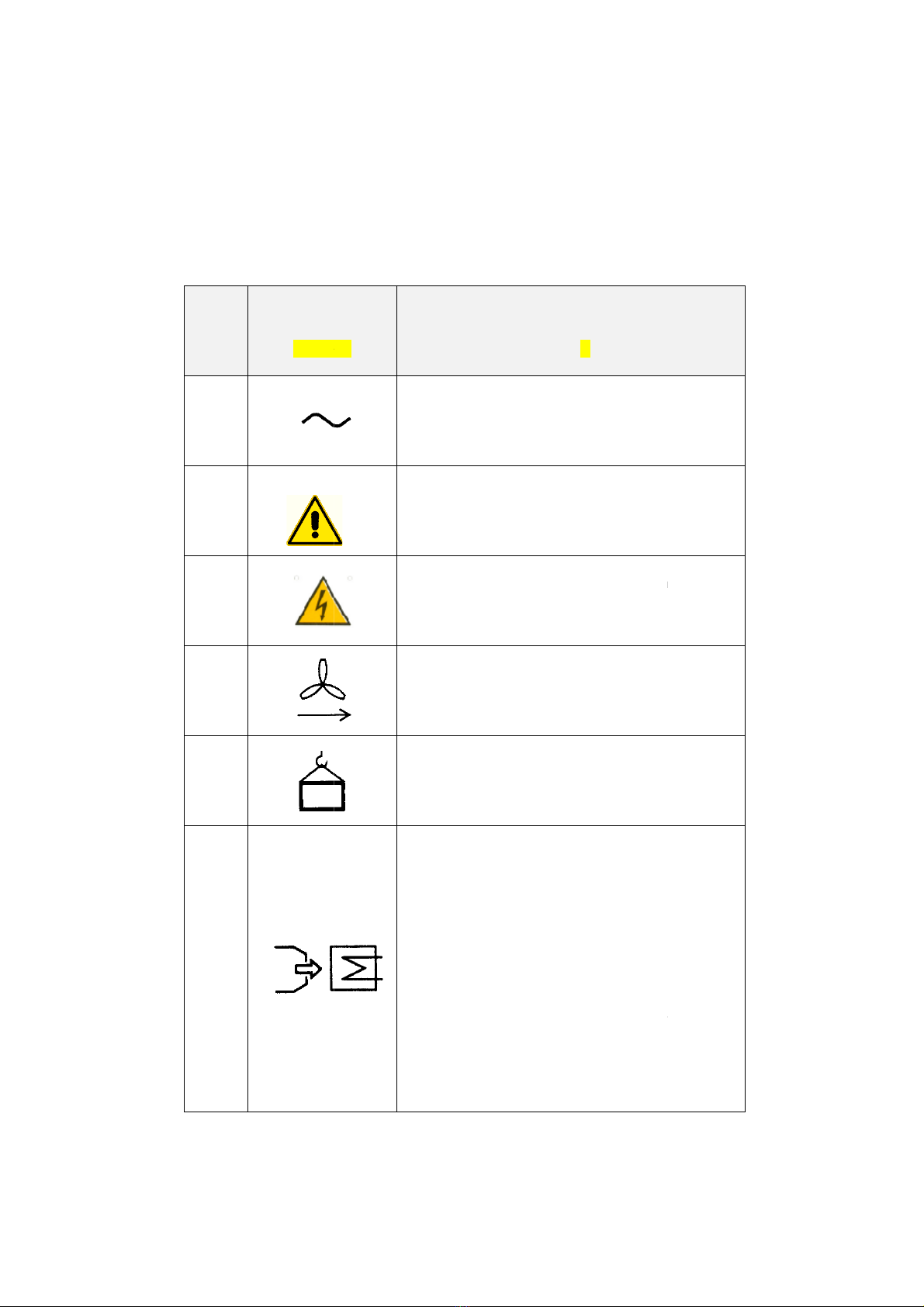
SYMBOLS ON THE UNIT
BODY
ICA
BOL
BOL
OLO
SIN
FUNZIONE
FUNCTION
FUNKTION
FUNCIÓN
FONCTION
Ingresso cavo elettrico
Electric cable inlet
Eingang Stromkabel
Entrada cable eléctrico
Entrée câble électrique
PERICOLO, PRESTARE ATTE
NZI
DANGER, PAY ATTENTION!
GEFAHR, VORSICHT!
¡PELIGRO, PRESTAR ATENCIÓ
DANGER, FAIRE ATTENTION
Pericolo ALTA TENSIONE sui compo
HIGH VOLTAGE on componen
Gefahr HOCHSPANNUNG an den Ba
¡Peligro ALTA TENSIÓN en los compo
Danger HAUTE TENSION sur les com
Senso di rotazione
Rotation direction
Drehrichtung
Sentido de rotación
Sens de rotation
Sollevamento (impiego dei golfa
Hoisting point (use eyebolts)
Heben (Hebeösen verwenden
Elevación (uso de l
os cáncamo
Levage (emploi des anneaux)
«
Pulire la batteria di raffreddamento so
macchina ferma con aria compressa
atm»
«
Clean the cooling coil using compre
pressurized max 6 atm and carry o
op
eration when the machine is not ru
«
Kühlbatterie monatlich reinigen. Bei s
Maschine mit Druckluft mit max. 6
ausblasen»
«Limpiar mensualmente la
baterí
enfriamiento. Soplar con la máquina pa
aire comprimido como má
x a 6 a
«
Nettoyer tous les mois la batteri
refroidissement.
Souffler quand la machine est arrêtée
comprimé à 6 atm max»
ZIONE!
N!
IÓN!
N !
onenenti!
nts!
Bauteilen!
ponente
s!
mposants !
lfari)
s)
en)
os)
x)
soffiando a
a a max 6
ressed air
out the
running
»
i stehender
. 6 atm
ría de
parada con
atm
»
rie de
e avec air

4
IMPORTANT WARNINGS
The indication IMPORTANT WARNINGS is used to focus attention on actions or
hazards that could damage the unit or its equipment
ENVIRONMENTAL PROTECTION
The indication Environmental Protection supplies instructions for use of the machine.
4. USER INSTRUCTION MANUAL
CONTENTS OF THE MANUAL
1. Introduction to the BICOLD WBA range ....................................................... 05
1-1 Description of BICOLD WBA units ...................................................... 05
1-2 Identification of the units ..................................................................... 07
1-3 Operating conditions and limits .......................................................... 08
1-4 Unit performance ................................................................................ 09
2. Installation requirements ............................................................................. 11
2-1 Lifting and transport ............................................................................ 11
2-2 Installation and positioning.................................................................. 13
2-3 Installation of electrical parts .............................................................. 15
3. Commissioning and running the chiller ........................................................ 17
3-1 Commissioning and operation notes.................................................. 17
3-2 Description of the electrical panel and controller ............................... 17
3-3 Operative settings of the controller .................................................... 24
3-4 Troubleshooting ................................................................................. 32
4. Maintenance ................................................................................................ 33
4-1 Periodic cleaning of the unit ............................................................... 33
4-2 Scroll compressor damage and replacement..................................... 34
4-3 Procedures in the event of prolonged inactivity of installed units........ 36
5. Warranty ..................................................................................................... 37
6. Scrapping / disposal of the unit at the end of its working life ....................... 37
Appendix I ……….. R410A technical data sheet (GB)

5
1. Introduction to the BICOLD WBA range
1.1 Description of the units
The WBA series constitutes a range of air-cooled water chillers designed to meet the
requirements of low and medium capacity air conditioning plants, operating with R410A, a
non-flammable and non-toxic high efficiency refrigerant for optimal energy saving in operation
of the unit.
The entire range is composed of 21 models characterised by the use of scroll compressors
connected in tandem for each circuit, with the exception of the first two sizes of the unit, which
are equipped with just one scroll compressor, by one or two separate refrigerant circuits, and
plate evaporators in brazed AISI stainless steel.
The fans installed are of the axial low-noise type.
The basic version is equipped with exclusively the plate evaporator. The equipment can
consist of a pump, pump with storage tank, dual pump, or dual pump with storage tank.
The pump and storage tank assembly is designated “hydronic unit”.
Control of the chillers is provided by an electronic microprocessor controller.
The refrigerant and hydraulic circuits comply with the PED directive.
Compressors
The compressors are of the hermetic scroll type with orbital scrolls. The rotating scroll is driven
by a two-pole motor cooled by the refrigerant on the suction line. All the compressors are
complete with a crankcase heater to prevent mixing of oil with the refrigerant during stoppages,
electronic thermal protection (if part of the equipment) and thermal overload protection.
All models in the WBA range feature a high pressure unloading function. When a high
condensing temperature is reached (as established by a pressure switch) due to abnormally
high ambient temperature, one compressor stops on each circuit. This results in oversizing of
the condensing coil surface area and dropping of the condensing temperature. Output in these
conditions is slightly higher than 50% of total output but it becomes unnecessary to stop the
unit so that cooling can continue throughout the critical period.
The compressors are filled with polyester oil, which is suitable for use in conjunction with
R410A.
Water-refrigerant plate evaporator
The evaporators are composed of AISI 316 stainless steel brazed plate exchangers. The
exchangers are clad externally with an anticondensation mat made of closed cell expanded
foam.
The exchanger is protected by a series of temperature probes installed on the refrigerant
discharge having an anti-freeze function, and by a pressure switch monitoring the pressure
differential between refrigerant suction and discharge sides.
Air-cooled condenser
The air-cooled condenser is composed of a finned core coil made with copper tubes and
high-efficiency corrugated aluminium fins adequately spaced in such a way as to ensure
optimal heat exchange efficiency. The copper tubes are of sufficient diameter and wall
thickness to withstand the highest R410A resign pressures.

6

7
Options:
•Metal mesh filters protecting the condensing coils.
Axial Fans
Axial fans with IP 54 protection rating, external rotor, with moulded blades made of
fibreglass-reinforced plastic with a die cast aluminium core.
The fans are accommodated in dynamically profiled external ports complete with a safety
mesh protecting the exterior side.
Electrical cabinet for power and control circuits
Electrical power and control cabinet, made in compliance with EN 60204-1/IEC 204-1 (Safety
of Machinery), complete with:
- control circuit transformer;
- main door-lock circuit breaker;
- thermal-magnetic cut-outs or fuses protecting compressors, fans and pumps
- contractors controlling compressors, fans and pumps;
- terminals for common alarms block;
- terminals for remote On/Off input;
- control circuit terminal boards;
- exterior quality electrical cabinet with single door and weather seals;
- electronic controller;
- control circuit numbered cables;
- 400/3/50Hz power supply; 230 Vac and 24 Vac control circuits for the electronic controller.
Options:
•phase sequence monitoring;
•electrical cabinet fan;
•electrical cabinet anticondensation heater;
•remote keypad kit.
Microprocessor controller
All WBA series units are equipped with a microprocessor controller capable of managing the
following functions:
-water temperature control in the traditional method with a probe on the system return line
(especially suitable for applications in which an inertia storage tank is installed);
-fans ON-OFF control;
-freeze protection;
-automatic compressors start sequence rotation;
-compressor time intervals;
-alarms signalling and reset;
-presentation on the display of the programmed set-points and the values read by the probes.

8
1.2
Identification of the units in the range
BICOLD WBA WATER CHILLERS
WBA 2 220 VDS MH
1 2 3 4 5 6
1 - MODEL
WB – Water chiller units with hermetic scroll
compressors and plate evaporators.
WH – Heat pump version
2 - CONDENSATION
A = AIR-cooling with axial fans (suitable for
outdoor installation);
3 – NUMBER of REFRIGERANT CIRCUITS
1 = one circuit
2 = two circuits
4 - SIZE
Numerical value denoting the cooping capacity in
kW in nominal conditions (water 12/7 °C and
ambient 35 °C)
5 - VERSION
STD = standard
6 – LAYOUT
SE = Unit with one evaporator. Including
differential pressure switch to protect the
evaporator.
MP = Unit with evaporator and one centrifugal
pump. Including a differential pressure switch
to protect the evaporator.
DP = Unit with evaporator and two centrifugal
pumps. Differential pressure switch to protect
the evaporator included.
MH = Unit with hydronic module; the layout
includes a centrifugal pump, storage tank,
water pressure relief valve and differential
pressure switch to protect the evaporator.
MHD = Unit with hydronic module; the layout
includes two centrifugal pumps, storage
tank, water pressure relief valve and
differential pressure switch to protect the
evaporator.
MC = Condensing unit; unit without
evaporator or expansion valve; supplied
without refrigerant charge.
.
9
1.3
Operating conditions and limits
Operating limits in Cooling Mode.
MIN MAX
Water inlet temperature °C 9 17
Water outlet temperature °C 5 13
Temperature gradient °C 4 8
Ambient air temperature °C 5 / -15 (*)
(**)
(*) First value refers to standard unit. Second value refers to unit with fans electronic control,
antifreeze heater on pump and storage tank (when present).
(**) Value depends on size of chiller and operating conditions.
Operating limits in Heating Mode.
MIN MAX
Water inlet temperature °C
25 45
Water outlet temperature °C
30
50 (***) / 40 (****)
Temperature gradient °C
4 8
Ambient air temperature °C
-5 20
(***) Max hot water outlet temperature with minimum ambient air temperature of +5 °C
(****) Max hot water outlet temperature with minimum ambient air temperature of -5 °C
In the presence of a risk of freezing of the fluid medium in the hydraulic circuit antifreeze
mixtures are required; the following are guideline values of the freezing point for mixtures of
water and ethylene glycol, withy glycol percentages expressed in weight. To avoid pump
damage in the event of glycol percentages above 25%, consult the BICOLD Srl sales
department.
The use of this type of mixture causes slight alterations in some of the thermodynamic
parameters of the chillers. The new values can be established by multiplying the value of the
required parameter in nominal operating conditions by the appropriate coefficients shown in
the following table:
% GLYCOL by weight
10
20
30
40
50
Freezing temperature (°C) -3.7 -8.7 -15.3 -23.5 -35 .6
Cooling capacity correction factor
0.99 0.98 0.97 0.96 0.93
Absorbed power correction factor
0.99 0.98 0.98 0.97 0.95
Mixture flow rate correction factor
1.02 1.05 1.07 1.11 1.13
Pressure drops correction factor 1.083 1.165 1.248 1.33 1.413

10
WARNING! WITHOUT GLYCOL IN THE SYSTEM:
IMPORTANT!
If the unit is not used in the winter the water in the circuit may freeze
IMPORTANT!
The use of mixtures of water with glycol affects performance characteristics of the unit
1-4 Unit performance
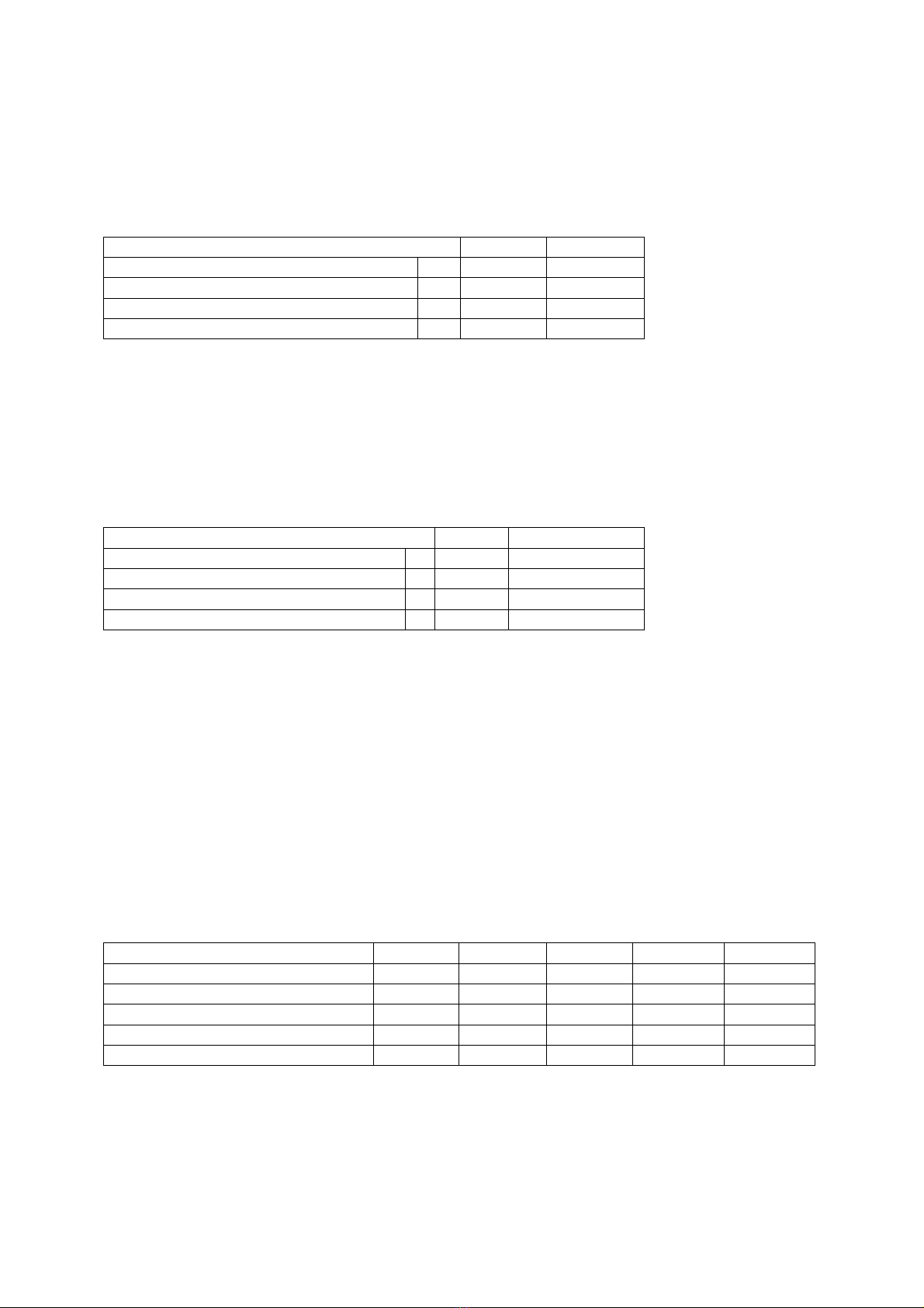
1.4.1 Cooling duty and electrical power consumption values
Performance values of the models in the WBA range of chillers are shown below referred to
water inlet/outlet temperature of 12/7 °C and ambie nt temperature of 35 °C.
Models
WBA
-
1020
WBA
-
1026
WBA
-
1030
WBA
-
1034
WBA
-
1039
WBA
-
1045
Cooling
DUTY kW 19,7 26,1 30,2 33,2 39,3 43,3
Power
CONS. kW 6,4 8,8 9,6 10,7 12,8 15,4
Models
WBA
-
1053
WBA
-
1059
WBA
-
1066
WBA
-
1075
WBA
-
1090
WBA
-
1098
WBA
-
1110
Cooling
DUTY kW 52.7 58.3 66.1 75 89.1 97.4 110.0
Power
CONS. kW 16.5 19.4 21.6 26.5 28.7 33.5 37.8
Models
WBA
-
1126
WBA
-
1145
WBA
-
1158
WBA
-
2180
WBA
-
2195
WBA
-
2220
Cooling
DUTY kW 125.7 144.2 157.6 178.2 194.9 224.0
Power
CONS. kW 40.8 46.5 54.5 57.4 67.0 75.7
Models
WBA
-
2250
WBA
-
2290
WBA
-
2315
WBA
-
2376
WBA
-
2412
Cooling
DUTY kW 249.3 288.4 315.2 375.5 412.0
Power
CONS. kW 82.3 92.2 109.0 116.0 135.2
11
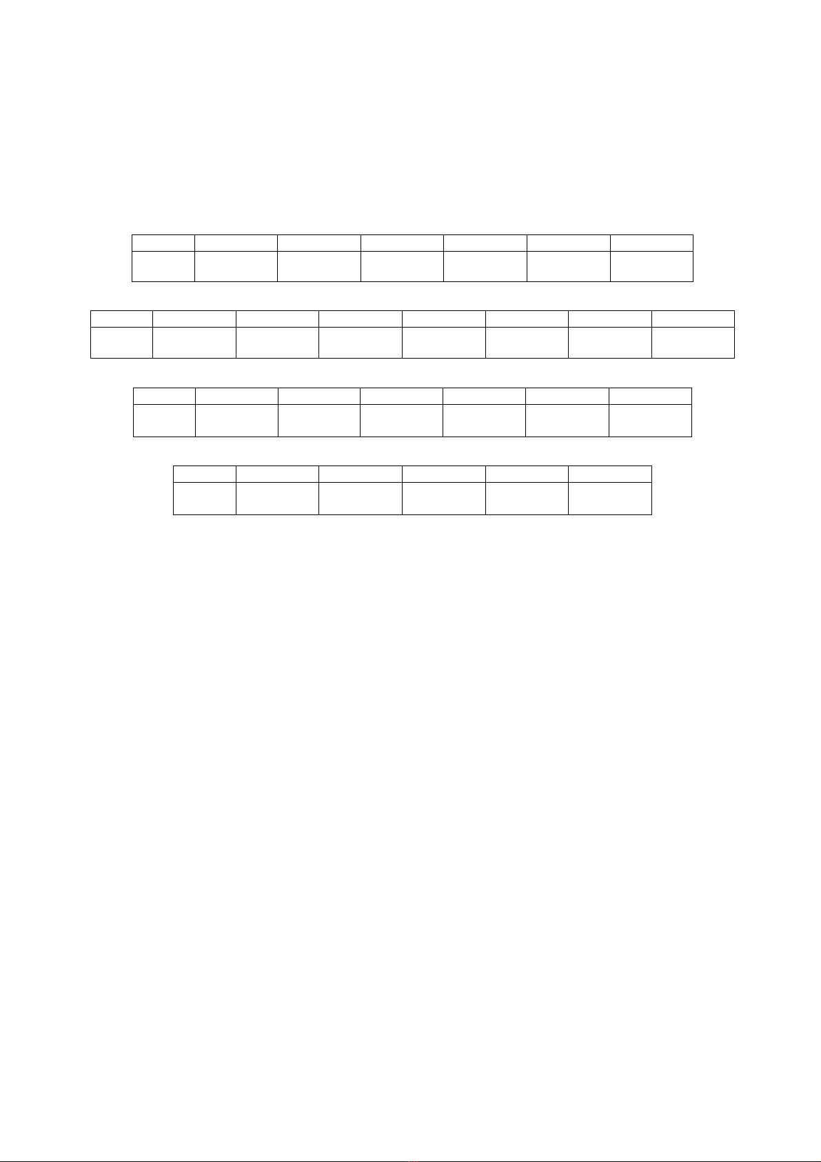
1.4.2 Sound pressure level
The following table gives the noise data in Sound Pressure Lp(A) at 10 metres from the
condensing coil and 1 metre height above ground in free field conditions (direction factor Q=2).
The Sound Pressure level refers to the machine std layout with the compressors compartment
insulated with sound absorbing matting.
Models
WBA
-
10
20
WBA
-
10
26
WBA
-
10
30
WBA
-
10
34
WBA
-
10
39
WBA
-
10
45
Lp(A)
10 m
47 48 48 48 49 49
Models
WBA
-
1053
WBA
-
1059
WBA
-
1066
WBA
-
1075
WBA
-
1090
WBA
-
1098
WBA
-
1110
Lp(A)
10 m
47 48 49 49 52 54 56
Models
WBA
-
1126
WBA
-
1
145
WBA
-
1158
WBA
-
2180
WBA
-
2195
WBA
-
2220
Lp(A)
10 m 57 57 57 55 57 59
Models
WBA
-
2250
WBA
-
2290
WBA
-
2315
WBA
-
2376
WBA
-
2412
Lp(A)
10 m 60 60 60 63 63

12
2 – INSTALLATION REQUIREMENTS
2.1 Lifting and transport

13
Before lifting the unit refer to the following WEIGHTS table, wherein values are calculated
without the hydronic unit:
Models
WBA
-
1020
WBA
-
10
26
WBA
-
10
30
WBA
-
10
34
WBA
-
10
39
WBA
-
10
45
Weight
kg 350 365 380 460 480 560
Models
WBA
-
1053
WBA
-
1059
WBA
-
1066
WBA
-
1075
WBA
-
1090
WBA
-
1098
WBA
-
1110
Weight
kg 620 635 665 680 870 950 1020
Models
WBA
-
1126
WBA
-
1145
WBA
-
1158
WBA
-
2180
WBA
-
2195
WBA
-
2200
Weight
kg 1100 1160 1180 1495 1665 1760
Models
WBA
-
2250
WBA
-
2290
WBA
-
2315
WBA
-
2376
WBA
-
2412
Weight
kg 2050 2100 2210 2630 2680
Models
WHA
-
1020
W
H
A
-
10
2
6
W
H
A
-
10
30
W
H
A
-
10
34
W
H
A
-
10
39
W
H
A
-
10
45
Weight
kg 380 400 415 500 530 620
Models
WHA
-
1053
WHA
-
1059
WHA
-
1066
WHA
-
1075
WHA
-
1090
WHA
-
1098
WHA
-
1110
Weight
kg 670 685 720 740 940 1030 1100
Models
WHA
-
1126
WHA
-
1145
WHA
-
1158
WHA
-
2180
WHA
-
2195
WHA
-
2200
Weight
kg 1190 1255 1280 1620 1800 1930
Models
WHA
-
2250
WHA
-
2290
WHA
-
2315
Weight
kg 2260 2310 2450
14
DANGER!
The unit must be handled with care to avoid damage to the external structure
and the internal mechanical end electrical components. Also make sure that
there are no obstacles or persons along the route, to avoid the risk of collision,
crushing or overturning of the lifting and handling vehicle.
The unit can be handled and/or lifted exclusively using the specific lifting attachments
incorporated in the frame.
Lifting of the unit is possible by means of textile webbing inserted in the channels in the
base frame, or by means of the forks of a suitable lift truck.
Once the unit has been installed remove the protective film from the panelling and the
shrink wrap plastic.
ENVIRONMENTAL PROTECTION
Dispose of the packing materials in compliance with national legislation and
local bylaws in your country.
DANGER!
Keep packaging materials out of reach of children.
2-2 Installation and positioning
(1) The chiller must be installed in a site with good air quality without a corrosive or
inflammable or exceptionally dusty atmosphere.
THE UNIT IS NOT SUITABLE FOR USE IN EXPLOSIVE
ATMOSPHERES!
(2) The chiller must be installed in a site in which ventilation is sufficient and the heat
release by the unit can be easily dispersed to the exterior. Considering that the chiller
disperses heat to the exterior when it is running, if the place of installation is confined or
lacks sufficient fresh air, the room temperature will rise progressively and the hot air, which
will recirculate over the condenser, will cause rapid degradation of the performance to the
point at which the unit shuts down due to high pressure.
IMPORTANT !
The unit must be sited taking account of the minimum
recommended clearances, taking account of the position of the
condensing coils and accessibility of the hydraulic and electrical
connections.
An installation without the recommended clearances will cause poor operation of the unit
with an increase in power consumption and a reduction in cooling capacity due to an
increase in the condensing pressure.

15
The area above the unit must be completely free of obstacles in such a way as to
guarantee unimpeded air flow from the condensing fans.
If the unit is surrounded by walls, the minimum clearances shown are still valid as long as
at least the two adjoining walls closest to the unit are no higher than the total height of the
unit.
Greater spaces than the spaces indicated must be provided to allow handling of any
components to be replaced.
WBA MODELS
10
20
/10
45
1053/1075
1090/1110
1126/1158
2180/2220
Installation
clearances
L1 mm
1000 1000 1000
1000
1000
L2 mm
1000 1000 1200 1200 1200
L3 mm
800
800
800
800
800
L4 mm
1000
1000
1000
1000
1000
WBA MODELS
2250/2315
2376/2412
Installation
clearances
L1 mm
1000 1000
L2 mm
1200 1200
L3 mm
800 800
L4 mm
1200 1200
(3) To ensure a sufficient air flow the condenser fins must NEVER be obstructed or
excessively fouled;
(4) Free air circulation around the electrical cabinet must be guaranteed.
(5) It is mandatory to install an 0.5 / 0.8 mm mesh filter on the chiller water inlet
16
2-3 Installation of electrical parts
WBA chillers are completely wired in the factory. The only cable required is the connection
to the electrical mains supply, the connection of the flow switch (optional) and the remote
On/Off switch (ON-OFF jumpered by default). All operations described above must be
carried out by qualified personnel in compliance with statutory legislation. For all electrical
work refer to the wiring diagrams.
General warning or precautions to be strictly observed. Serious hazard.
Electric shock hazard
THE UNIT ELECTRICAL HOOK-UP MUST BE CARRIED OUT BY A LICENSED
ELECTRICIAN WITH THE NECESSARY PROFESSIONAL SKILLS AND IN
COMPLIANCE WITH STATUTORY REGULATIONS IN THE COUNTRY OF
INSTALLATION !
IMPORTANT ! FOR INSTALLATION REFER TO THE UNIT WIRING DIAGRAMS
SUPPLIED ON BOARD THE UNIT TOGETHER WITH THIS MANUAL, AND TO THE
DATA ON THE CE RATING PLATE
(1)
The unit must be connected to the power supply only when the installation work
(mechanical, hydraulic and electrical) has been completed.
(2)
The electronic control board is located in the chiller electrical cabinet.
Only qualified technicians must open the unit to perform work on it. To hook up the
WBA unit to the mains electrical panel, for power feeding and for the signals
input/output, always refer to the wiring diagram.
(3)
Comply with the connection specifications for the phase and protective earth
conductors. There must be a specific protection against short circuits and ground
faults upline from the power feeding line, capable of disconnecting the plant from
all other users.
(4)
Install suitable protection on the WBA unit power feeding line in compliance with
the regulations in force in the country in which the unit is installed.

17
(5)
For the electrical connections use cables that comply with the statutory electrical
regulations in force in the country of installation
(6)
After installation, check that the mains power values are within a tolerance of ±10%
of the nominal machine input voltage (unless otherwise specified on the electrical
wiring diagram) with a maximum phase-to-phase imbalance of 3%. If these
parameters are not present, contact your local electricity company.
(7)
No external thermostat can be used to connect/disconnect the unit’s power
feeding line, or malfunctions and poor performance of the unit will result.
(8)
Keep the power lines separate from the signal cables; signal cables must be
shielded and connected to a voltage-free PE point at just one end of the shield.
(9)
It is mandatory to make an efficient protective earth connection. The manufacture
cannot be held liable for any damage caused by the omitted or inefficient
connection of the unit to the earth system.

18
3. Commissioning and running the chiller
3-1 Commissioning and operation notes
Before starting up the unit check that the water circuit pipes have been
correctly connected to the evaporator and that the electrical panels and condenser
compartment doors are properly closed. At this point the chiller can be started.
Pay attention to moving parts if the panels or covers
are raised or have been removed from the unit!
Access to the unit is permitted only to qualified technical personnel.
3-2 Description of the electrical panel and controller
The electrical panel is located inside the unit at the top of the technical compartment that
houses the various refrigerant circuit components.
To gain access to the electrical panel open the front panel of the unit after setting the door
lock breaker switch to 0 (OFF).
OPERATION AND ADJUSTMENT
The electrical cabinet is equipped with a main disconnect switch with door-lock device.
Feeding of the 230Vac auxiliary circuits and the 24Vac control circuits is obtained internally
from the three-phase power input. Adjustments can be carried out by means of a compact
electronic controlled, of the size of a normal thermostat, which provides complete
management of the chiller.
Unit regulation and switching-on of the external high and low prevalence
pumps.
The water temperature probe which controls the thermoregulation of the machine, is
positioned on the pipe that connects the water tank to the evaporator inlet.
The microprocessor switches on or off the compressor according to the temperature set.
The inner circulatory pump is always switched on. This pump makes the water flow circulate
between the tank and the evaporator.
The 2 external pumps for the users pumping, are regulated by a 3-positions selector according
to the following logic:
“Man” position: the pump is switched on
“0” position: the pump is switched off
“Auto” position: the pump is switched on by an external contact (at customer’s charge) as
quoted on the electrical scheme.
19
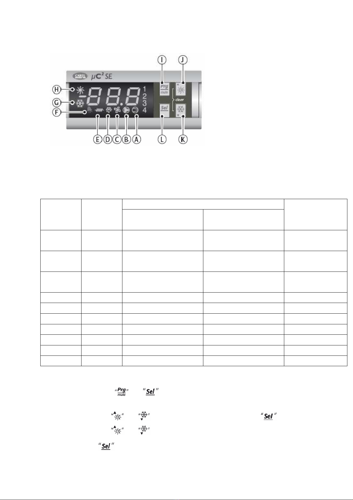
1. USER INTERFACE
SYMBOL COLOUR MEANING REFERENCE
REFRIGERANT
CIRCUIT
WITH LED
ON WITH LED
FLASHING
1;2 amber Compressor 1 and/or 2
running Start request 1
3;4 amber Compressor 3 and/or 4
running Start request 2
A amber At least one compressor
running 1/2
B amber Pump running Start request 1/2
C amber Condenser fan running 1/2
D amber Defrost on Defrost request 1/2
E amber Crankcase heater on 1/2
F red Active alarm 1/2
G amber Heat pump mode Heat pump mode request 1/2
H amber Chiller mode Chiller mode request 1/2
1. PARAMETERS PROGRAMMING AND SAVING PROCEDURE
Press and for 5 s;
The hot and cold symbol and the value “00” will appear;
Use and to set the password and confirm with ;
Use and to select the parameters menu
and confirm with
;
20
Use and to select the parameters group and confirm with ;
Use and to select the parameter and confirm with ;
Once the parameter has been edited press to confirm or to
cancel your changes;
Press to restore the previous menu;
NOTES:
Parameters edited without confirmation by pressing will simply
revert to the previous value;
If no keys are pressed for 60 s, the controller will quit the parameters
editing menu due to time-out and the changes that have been made will
be cancelled.
1. SWITCHING THE UNIT ON AND OFF
Turn the main power switch to 1(ON).
CHILLER OPERATION
To start the unit hold down the key for 5 seconds. The pump
operating mode LEDs will light.
Depending on the return temperature from the installation one or both
compressors may be started.
To stop the unit hold down the key for 5 seconds.
HEAT PUMP OPERATION
To start the unit hold down the key for 5 seconds. The pump operating
mode LEDs will light.
Depending on the return temperature from the installation one or both
compressors may be started.
To stop the unit hold down the key for 5 seconds.
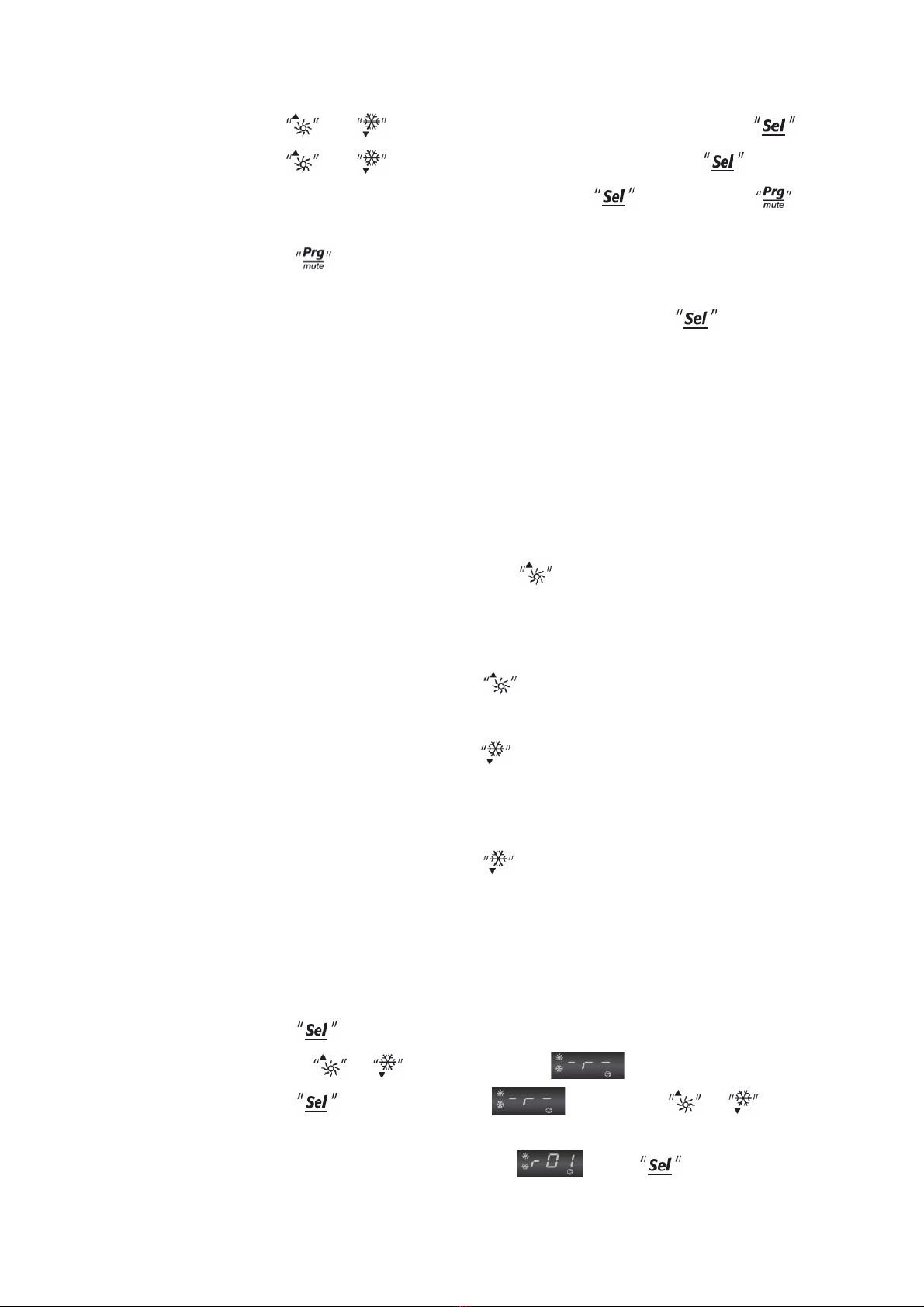
2. PROGRAMMING THE SET-POINT
CHILLER MODE OPERATION
The factory setting in cooling mode is 9.5°C.
To change the set point, proceed as follows:
Press for 5 sec to access the main parameters window.
Use the or key to scroll to the submenu.
Press to access submenu and use the or key to
scroll through the parameters accessible from said menu.
To change the Set-point, parameter , press
This manual suits for next models
47
Table of contents
Popular Chiller manuals by other brands

York
York YCAS Series Installation operation & maintenance

Carrier
Carrier OPEN-DRIVE CENTRIFUGAL LIQUID CHILLERS 17CB Start-up instructions

York
York YCAS0250 Wiring diagram

Instanta
Instanta UCCH1000 INSTALLATION INFORMATION & USER INSTRUCTIONS

Daikin
Daikin MicroTech II Installation and maintenance manual

York
York YVAA Installation operation & maintenance


Carrier
Carrier AquaEdge 23XRV installation instructions

LG
LG RCWFL Series installation manual

Kaysun
Kaysun KEM-30 DRS4 Service manual

CLIVET
CLIVET WSH-EE Series Installation and use manual

Robur
Robur GA ACF Installation, use and maintenance manual

Trane
Trane Koolman R410A Installation, operation and maintenance