YORK INTERNATIONAL
4
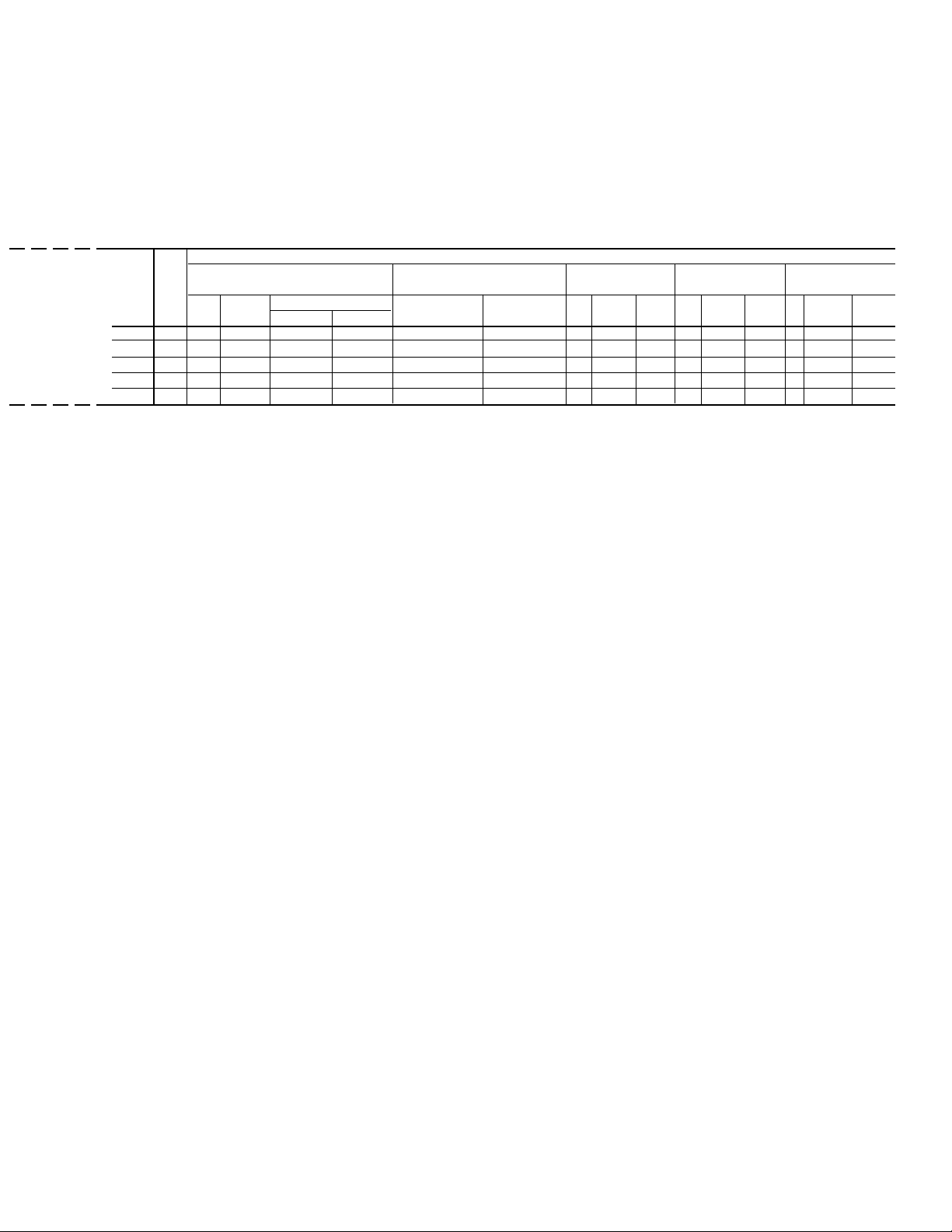
60 Hz MULTIPLE POINT POWER SUPPLY CONNECTION
(Two Field Provided Power Supply Circuits to the Chiller. Field Connections to Factory provided Terminal Block (Std)
or Disconnects (Opt) in the Options Panel. Circuit Breaker (opt10) in each of the two Motor Control Centers.)
Electrical System #1 Field Supplied Wiring
Chiller Field Provided Power Supply Factory Provided (Lugs) Wire Range7Compressor #1 Compressor #3 Fan11, 12
Model Data
YCAS Volts MCA1Min NF Over-Current Protection13 Standard Optional NF RLA Y-
∆
LRA XL-LRA RLA Y-
∆
LRA XL-LRA Qty FLA (ea) LRA (ea)
Disc SW2Min.3, 5 Max.4, 6 Terminal block Disc. Switch
380 387 400 450 500 (1)1/0-(2)4/0AWG 250-500 kcm 155 343 1,093 155 343 1,093 8 4.8 23.0
0250EC 460 320 400 400 400 (1)1/0-(2)4/0AWG 250-500 kcm 128 280 893 128 280 893 8 4.0 19.0
575 257 400 300 350 (1)1/0-(2)4/0AWG 250-500 kcm 103 224 714 103 224 714 8 3.1 15.2
380 477 600 600 700 (2) 2AWG-300kcm (2) 250-500kcm 155 343 1,093 227 343 1,093 8 4.8 23.0
0270EC 460 390 400 450 500 (1)1/0-(2)4/0AWG 250-500 kcm 128 280 893 184 280 893 8 4.0 19.0
575 312 400 350 450 (1)1/0-(2)4/0AWG 250-500 kcm 103 224 714 147 224 714 8 3.1 15.2
380 473 600 600 600 (2) 2AWG-300kcm (2) 250-500kcm 181 343 1,093 199 343 1,093 9 4.8 23.0
0300EC 460 390 400 450 500 (1)1/0-(2)4/0AWG 250-500 kcm 149 280 893 164 280 893 9 4.0 19.0
575 311 400 350 400 (1)1/0-(2)4/0AWG 250-500 kcm 119 224 714 131 224 714 9 3.1 15.2
380 524 600 600 700 (2)1/0AWG-500kcm (2) 250-500kcm 197 343 1,093 227 343 1,093 9 4.8 23.0
0330EC 460 429 600 500 600 (2) 2AWG-300kcm (2) 250-500kcm 163 280 893 184 280 893 9 4.0 19.0
575 342 400 400 500 (1)1/0-(2)4/0AWG 250-500 kcm 130 224 714 147 224 714 9 3.1 15.2
ELECTRICAL DATA (60 Hz)
NOTES
1. Minimum circuit ampacity (MCA) is based on 125% of the rated load amps for the largest motor plus 100% of the rated load amps for all
other loads included in the circuit, per N.E.C. Article 430-24. If a Factory Mounted Control Transformer is provided, add the following to
the system #1 MCA values in the YCAS Tables: -17, add 15 amps; -28, add 12 amps; -40, add 7 amps; -46, add 6 amps; -58, add 5 amps.
2. The recommended disconnect switch is based on a minimum of 115% of the summation rated load amps of all the loads included in the
circuit, per N.E.C. 440 - 12A1.
3. Minimum fuse size is based on 150% of the largest motor RLA plus 100% of the remaining RLAs (U.L. Standard 1995, Section 36.1).
Minimum fuse rating = (1.5 x largest compressor RLA) + other compressor RLAs + (# fans x each fan motor FLA).
4. Maximum dual element fuse size is based on 225% maximum plus 100% of the rated load amps for all other loads included in the circuit,
per N.E.C. 440-22. Maximum fuse rating = (2.25 x largest compressor RLA) + other compressor RLAs + (# fans x each fan motor FLA).
5. Minimum circuit breaker is 150% maximum plus 100% of rated load amps included in the circuit, per circuit per U.L. 1995 Fig. 36.2.
Minimum circuit breaker rating = (1.5 x largest compressor RLA) + other compressor RLAs + (# fans x each fan motor FLA).
6. Maximum circuit breaker is based on 225% maximum plus 100% of the rated load amps for all loads included in the circuit, per circuit,
per U.L. 1995 Fig. 36.2. Maximum circuit breaker rating = (2.25 x largest compressor RLA) + other compressor RLAs + ( # fans x each
fan motor FLA).