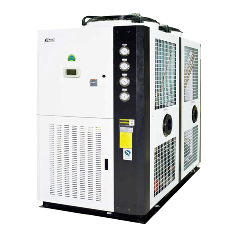
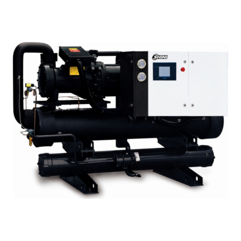
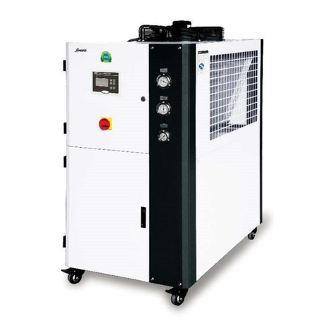
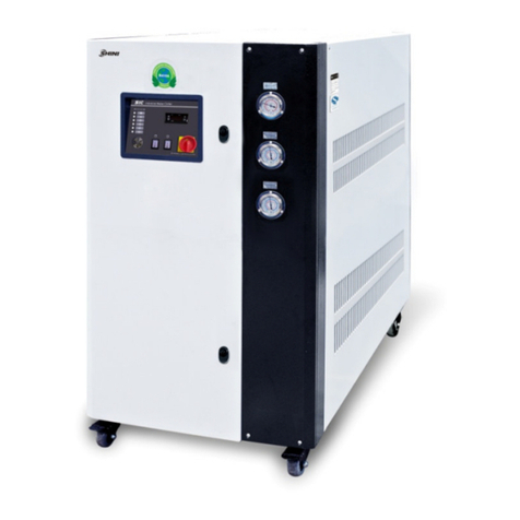
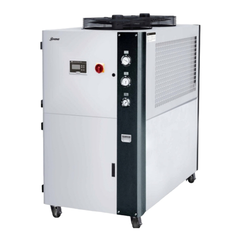
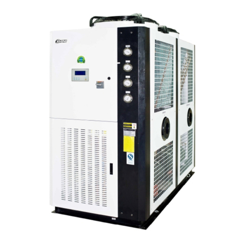
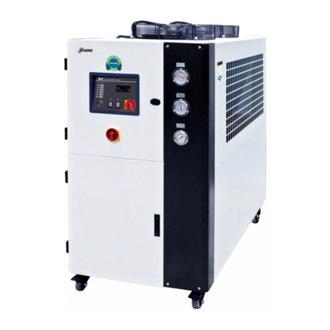
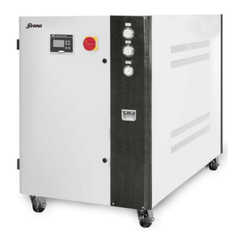
Shini SIC-R2 Series User manual

SIC-R2
Operation ManualofCFC-free
RefrigerantWater Chiller
Date:Jun,2017
Version: Ver.D(English)


3(49)
Contents
1. General Description..................................................................................... 7
1.1 CodingPrinciple......................................................................................8
1.2 MainFeatures.........................................................................................8
1.3 TechnicalSpecifications........................................................................ 10
1.3.1 ExternalDimensions................................................................... 10
1.3.2 Specification List......................................................................... 13
1.4 SafetyRegulations................................................................................ 16
1.4.1 SecurityLabels........................................................................... 16
1.4.2 Signsand Labels........................................................................ 17
1.5 ExemptionClause................................................................................. 18
2. Structural Features and Working Principle.............................................. 19
2.1 MainFunctions...................................................................................... 19
2.1.1 WorkingPrinciple........................................................................ 19
2.2 MainPartsandFunctions..................................................................... 22
2.2.1 Compressor................................................................................ 22
2.2.2 Condensor.................................................................................. 22
2.2.3 DryingFilter................................................................................ 23
2.2.4 Evaporator.................................................................................. 23
2.2.5 Highand LowPressureSwitch................................................... 24
2.2.6 Hot Air Bypass Valve.................................................................. 24
2.3 Options.................................................................................................. 24
2.3.1 LiquidLevelIndicator.................................................................. 24
2.3.2 LiquidPipe SolenoidValve......................................................... 25
2.3.3 RefrigerantIndicator................................................................... 25
2.3.4 FlowSwitch................................................................................ 26
2.3.5 Mediumorhighpressurepumps................................................ 26
3. Installation and Debugging........................................................................ 27
3.1 Machine Location.................................................................................. 27
3.2 PowerConnectors................................................................................. 27
3.3 Waterconnections................................................................................ 28
3.3.1 Noticeof PipelineInstallation...................................................... 29

4(49)
3.4 WaterTankFilling................................................................................. 30
4. Application and Operation......................................................................... 31
4.1 PanelDiagram...................................................................................... 31
4.2 CommonScreens................................................................................. 31
4.3 Quick Operation.................................................................................... 32
4.4 Startup .................................................................................................. 33
4.5 Shutdown.............................................................................................. 33
4.6 UserMenu............................................................................................ 34
4.6.1 ParameterOperation.................................................................. 34
4.6.2 UserSetting................................................................................ 34
4.6.3 Machine Set................................................................................ 35
4.6.4 SystemTimeSet........................................................................ 35
5. Trouble-shooting ........................................................................................ 36
6. Maintenance and Repair............................................................................ 40
6.1 Fill inthe Refrigerant............................................................................. 44
6.2 ComponentsMaintenance.................................................................... 45
6.2.1 Condenser.................................................................................. 45
6.2.2 Evaporator.................................................................................. 46
6.3 MaintenanceSchedule.......................................................................... 48
6.3.1 About theMachine...................................................................... 48
6.3.2 Check afterInstallation ............................................................... 48
6.3.3 DailyChecking............................................................................ 48
6.3.4 WeeklyChecking........................................................................ 48
6.3.5 MontlyChecking......................................................................... 48
6.3.6 TrimonthlyChecking................................................................... 49
6.3.7 Half-yearlyChecking................................................................... 49
6.3.8 YearlyChecking.......................................................................... 49
6.3.9 3yearChecking.......................................................................... 49
TableIndex
Table1-1: Specifications.................................................................................. 11
Table1-2: SpecificationList (SIC-W-R2).......................................................... 13

5(49)
Table1-3: SpecificationList (SIC-A-R250HZ)................................................. 14
Table1-4: SpecificationList (SIC-A-R260HZ)................................................. 15
PictureIndex
Picture1-1: Outline DimensionalDrawing........................................................ 10
Picture2-1:WorkingPrinciple.......................................................................... 19
Picture2-2:WorkingPrinciple.......................................................................... 20
Picture2-3: Compressor................................................................................... 22
Picture2-4: Condenser..................................................................................... 22
Picture2-5: Condenser..................................................................................... 23
Picture2-6: DryingFilter................................................................................... 23
Picture2-7: Evaporator..................................................................................... 23
Picture2-8: HotAir Bypass Valve..................................................................... 24
Picture2-8: LiquidLevelIndicator..................................................................... 24
Picture2-9: LiquidPipeSolenoidValve............................................................ 25
Picture2-10: Refrigerant Indicator.................................................................... 25
Picture2-11: FlowSwitch................................................................................. 26
Picture3-1: Installation Diagram....................................................................... 28
Picture3-2: Installation Diagram....................................................................... 29

6(49)

7(49)
1.General Description
Pleaseread throughthis operationmanualbeforeusingand installation to
avoiddamage of themachineandpersonalinjuries.
SIC-R2waterchillercomprisesoftwoseries;water-cooled andair-cooled, both
adopt singlevaporcompressioncircuit and equippedwithcompressoroverload
protection,pumpoverload protection,anti-phaseand openphasealarm,
anti-freezeprotection,pressurecontrollerwhichall ensureastableand
long-service-lifeperformance.Thiscoolerseriescan coolquicklyand stablyto
meet thecustomerrequirements. It works based onthe principleofheatandcold
exchange. It isindispensableequipmentinmodernindustry.
Model: SIC-33W-R2Model: SIC-7.5A-R2

8(49)
1.1CodingPrinciple
1.2MainFeatures
Coolingrange7~25 .
Insulated watertankand evaporatormadeofstainless steel.
Equipped withanti-freezetherostate.
Adopt R410A refrigeranttoimprovecoefficientofperformance(COP)and
R410A isozone-friendly.
Refrigerationloopcontrolledbyhighandlowpressureswitchestoensure
stableoperation.
Compressorandpumpoverload protection.
Adoptprecisehigh-precision temperaturecontrollerwithan accuracyof ±1
All adopt qualitycompressorsfrommajorsupplier.
Single-systemcoolerisequippedwithlowpressurepumpsasstandard
configurations, whiletwo-systemandabovecoolerareequipped with
mediumpressurepumpsasstandardconfigurations.
SIC-W-R2Adopttube-in-shell condenserwithexcellentheat transferand
rapidcooling.

9(49)
SIC-A-R2Adopt finstylecondenserdesign.Withoutanyneed ofcoolingwater
forexcellent heattransferandrapidcooling.
Hot air bypass valvecan beoptedforbalancingcoolingcapacitytoachieve
accuratetemperaturecontrolandprevent machine starts/stopsfrequently.
EquippedwithRS485communication interfacetorealizecentralized
monitoring.
All serviceworkshouldbe carried out byaperson withtechnicaltrainingor
correspondingprofessionalexperience.The manualcontainsinstructionsforboth
handlingand servicing.Chapter7, whichcontainsserviceinstructionsintendedfor
serviceengineers. Otherchapterscontaininstructionsforthedailyoperator.
Anymodificationsofthemachinemustbe approved bySHINI inordertoavoid
personalinjuryand damagetomachine.Weshall not beliableforanydamage
causedbyunauthorized changeof themachine.
Ourcompanyprovidesexcellent after-salesservice. Shouldyou haveanyproblem
duringusingthemachine,pleasecontactthecompanyorthelocalvendor.
HeadquarterandTaipeifactory
Tel:(886)226809119
ShiniPlastics Technologies(Dongguan), Inc
Tel:(86)769 81116600
ShiniPlastics TechnologiesIndiaPvt.Ltd.
Tel:(91)250 3021166

10(49)
1.3Technical Specifications
1.3.1ExternalDimensions
(SIC-W-R2Series)
SIC-9W~42W-R2SIC-56W~84W-R2
SIC-112W~132W-R2
(SIC-A-R2Series)
SIC-7.5A-R2~SIC-38A-R2SIC-48A-R2~SIC-75A-R2
SIC-100A-R2~SIC-114A-R2
Picture1-1: Outline DimensionalDrawing

11(49)
Table1-1: Specifications
Model H
(mm)
H1
(mm)
H2
(mm)
H3
(mm)
W
(mm)
W1
(mm)
W2
(mm)
W3
(mm)
D
(mm)
SIC-9W-R2 970 790 91 207 605 273 164 164 1080
SIC-14W-R2 970 790 91 207 605 273 164 164 1080
SIC-21W-R2 1050 910 140 225 830 370 230 230 1200
SIC-28W-R2 1050 910 140 225 830 370 230 230 1200
SIC-33W-R2 1200 1078 140 308 865 459 202 162 1470
SIC-42W-R2 1200 1078 140 308 865 459 202 162 1470
SIC-56W-R2 1450 765 200 190 1055 300 295 205 2235
SIC-66W-R2 1450 765 200 190 1055 300 295 205 2235
SIC-84W-R2 1450 765 200 200 1055 300 215 205 2235
SIC-112W-R2
1760 750 140 190 1100 300 260 267 2870
SIC-126W-R2
1760 490 140 190 1100 300 230 250 3052
SIC-132W-R2
1760 520 140 190 1100 205 325 505 3285
Model
P1
CoolingWater
Inlet
(inch)
P2
CoolingWater
Outlet(inch)
P3
Process
Water
Inlet(inch)
P4
Process Water
Outlet(inch)
P5
WaterTank
OutletPort
(inch)
P6
WaterTank
OverflowPort
(inch)
Weight
(kg)
SIC-9W-R2 11/211/21 1 1/2 1/2 210
SIC-14W-R2 11/211/21 1 1/2 1/2 240
SIC-21W-R2 11/211/211/211/21/2 1/2 330
SIC-28W-R2 11/211/211/211/21/2 1/2 340
SIC-33W-R2 2 2 2 2 1/2 1/2 430
SIC-42W-R2 2 2 2 2 1/2 1/2 495
SIC-56W-R2 21/221/22 2 1/2 1/2 750
SIC-66W-R2 21/221/22 2 1/2 1/2 760
SIC-84W-R2 21/221/221/221/21/2 1/2 800
SIC-112W-R2
21/221/221/221/21/2 1/2 1200
SIC-126W-R2
21/221/221/221/21 1 1450
SIC-132W-R2
2×21/22×21/221/221/21 1 1750
Model H
(mm)
H1
(mm)
W
(mm)
W1
(mm)
W2
(mm)
D
(mm)
P1
Chilled
Water
Inlet (inch)
P2
Chilled
Water Outlet
(inch)
P3
Water Tank
Outfall (inch)
P4
Water Tank
Overfall
(inch)
P5
Water Tank
RefillPort
(inch)
Weight
(kg)
SIC-7.5A-R2
1200
625
685
277
200
1190
1 1 1/2 1/2 1/2 305
SIC-12A-R21490
640
735
360
174
1320
1 1 1/2 1/2 1/2 315
SIC-18A-R21430
640
735
300
204
1610
11/211/21/2 1/2 1/2 400
SIC-24A-R21440
640
735
300
204
1610
11/211/21/2 1/2 1/2 420
SIC-28A-R21560
726
905
390
223
1782
11/211/21/2 1/2 1/2 530
SIC-38A-R21560
726
905
390
223
1782
2 2 1/2 1/2 1/2 540
SIC-48A-R21942
755
1208
400
257
2922
2 2 1 1/2 1/2 775
SIC-58A-R21942
755
1208
400
257
2922
2 2 1 1/2 1/2 800

12(49)
SIC-75A-R21942
755
1208
418
257
2922
21/221/21 1/2 1/2 840
SIC-100A-R2
1942
641
1300
800
243
3475
21/221/21 1 1 1400
SIC-114A-R2
1942
641
1300
900
255
3475
21/221/21 1 1 1600

13(49)
1.3.2Specification List
Table1-2: SpecificationList (SIC-W-R2)
ModelSIC-
Item/Parameters
9W-R2
14W-R2
21W-R2
28W-R2
33W-R2
42W-R2
56W-R2
66W-R2
84W-R2
112W-R2
126W-R2
132W-R2
Ver. C C C C C C B B B B B B
Refrigerant
Capacity 1)
kW
50Hz
9 14 21 28 33 42 56 66 84 112 126 132
60Hz
10.8
16.8 25.2 33.6 39.6 50.4 67.2 79.2 100.8 134.4 151.2 158.4
kcal/hr
50Hz
7,740
12,040
18,060
24,080
28,380
36,120
48,160
56,760
72,240
94,320 108,360
113,520
60Hz
9,288
14,448
21,672
28,896
34,056
43,344
57,792
68,112
86,688
115,584
130,032
136,224
Compressor
Power
(kW)
Type
Scroll
50Hz
2.5 3.55 5.5 7.35 8.35 10.5 14.7 16.7 21 28.35 31.5 33.4
60Hz
3.2 4.5 6.4 8.5 9.75 12.5 17 19.5 25 33.5 37.5 39
Refrigerant
Weight(kg) 2.5 3.0 5.5 5.5 9.8 8.7 10.8 16 17.4 21.4 26.1 32
ControlMode Thermostaticexpansionvalve
Type R410A
Evaporator
Type Tube-in-shell style
Condenser
Type Tube-in-shell style
In/outPipe(inch) 11/22 21/22x21/2
CoolingWater
Flow(L/min) 33.5
52.2 78.3 104.3
123 156.5 208.7 246 313 417.4 469.6 491.9
WaterTank(L) 40 70 80 200 400
Pump2)
Power
(kW)
50Hz
0.75/0.75/ 1.1
1.1/ 1.1/ 1.1 1.1/1.5/2.2 2.2/1.8/2.4 2.2/3.0/4.0 2.2/4.0/5.5
60Hz
0.75/0.75/ 1.5
1.1/ 1.1/ 1.5 2.2 3 5
PumpFlow
(L/min)
50Hz
25.8
40.1 60.2 80.3 94.6 120.4 160.5 189.2
240.8 321.1 361.2 378.4
60Hz
30.9
48 71.9 96 113 147.2 191.7 226 287.7 383.6 431.6 452.2
Working
Pressure
(kg/cm2)
50Hz
3.3/3.7
/4.5
3.1/3.5
/4.3
2.8/3.9
/5.7
2.7/3.3
/4.0
2.7/3.7
/4.7
2.6/3.5
/4.5 -/3.2/4.4
-/3.1/4.1
-/3.4/4.1
-/2.8/3.8
-/3.7/4.4
-/3.2/4.3
60Hz
-/3.50
/5.4
-/2.90
/5
-/3.35
/4.5 -/3.90/-
-/4.0/5.4
-/5.0/6.2
-/4.1/5.1
-/4.4/-
- - - -
TotalPower3)(kW)
50Hz
3.25
4.3 6.61 8.45 9.45 11.6 16.9 18.9 23.2 30.55 32.7 35.6
60Hz
3.15
5.6 7.22 9.21 11.39
14.6 19.22 21.38
30.3 38.41 42.7 42.26
Pipe
cooling
(inch)
Chilled wateroutlet 1×1 11/2×1 2×1 21/2×1 21/2×1
Chilled waterinlet 1×1 11/2×1 2×1 21/2×1 21/2×1
Drainageport
ofwatertank 1/2 1
Overfloweport
ofwatertank 1/2 1
Protections
Compressor Overload relay
Pump Overload relay
RefrigerantCircuit High andlowpressureswitch/anti-freezeswitch
Coolingwaterciucuit By-passvalve/Waterlevelswitch(Option)
OperationNoiseDb(A) 69 70.5 70.4 12.5 71.4 74 75.5 73.3 78.5 81.4 79.6 86.5
Power 3Φ,230/ 400/ 460/ 575VAC,50/ 60Hz
MeasuresExchange 1kW=860kcal/hr1RT=3024kcal/hr10000Btu/hr=2520kcal/hr
Note:1)Refrigerationcapacityisbasedontheflow0.172m3/ (h.kW)and theoutlet temperatureof 7℃/44.6°Fof chilled waterundertheenvironmenttemperatureof30℃/86°F
andcoolingwaterflowof 0.215 m3/(h.kW).
2)Theworkingpressureofwaterpumpisthepressurewhennegativepressureof inlet wateris0.
3)Thispumpisusedasstandardeitherfordomesticofsoutheastaisa;medium(Modeldenotes"P",suchasSIC-9W-R2-P)orhighpressurepumps(Modeldenotes
"HP",suchasSIC-9W-R2-P),areoptionalforoptionalforinstallationoncustomer'sdemands.
4)Pumppowerisincludedintotalpower.
5)Demandsonspecialvoltageof powersupplycouldbesatisfied.

14(49)
Table1-3: SpecificationList (SIC-A-R250HZ)
ModelSIC-
Item/Parameters 7.5A-R2
12A-R2
18A-R2
24A-R2
28A-R2
38A-R2
48A-R2
58A-R2
75A-R2
100A-R2
114A-R2
Ver. C C C C D D B B B B B
Refrigerant
Capacity 1)
kW7.512 18 24 28 38 48 58 75 100 114
Refrigerant
Capacity 2)
kW9.5 14 24 32 38 45 64 76 90 121 135
Compressor
Type Scroll
Power 2.94.2
6.4 8.72
9.36
12.25 17.44 18.72 24.86
33.58 37.29
Refrigerant
Weight(kg)3.5 5.0 5.5 5.5 9.0 12.5 7.5x2 8x2 7.8x2+6.8
8.7x3
ControlMode Thermostaticexpansionvalve
Type R410A
Evaporator Type Tube-in-shell style
Condenser
Type Finstyle
Blower(kW) 0.19 0.55
2×0.23
2×0.385
2×0.6 2×0.78
2×1.03
2×0.85
2×1.92
2×2.2+1.5
3×2.2
WaterTankCapacity(L)30 65 80 186 230 316
Pump 2)
(50Hz/60Hz)
Power(kW) 0.75/0.75/ 1.1
1.1/ 1.1/ 1.1 1.1/1.5/2.2 -/1.8/2.4 -/3.0/4.0 -/4.0/5.5
PumpFlow(L/min) 21.5 34.4 51.6 68.8 80.3 108.9 137.6 166.3 215.0
286.7 32.8
WorkingPressure(kg/cm2)
3.3/3.7
/4.5
3.2/3.5
/4.4
2.8/4.1
/4.9
2.7/3.85
/4.5
3.1/3.9
/4.9
2.4/3.8
/4.6
-/3.4/4.5
-/3.2/4.3
-/3.5/4.1
-/3.1/3.9
-/3.7/4.9
TotalPower(kW)(50Hz/60Hz)
3.8/3.8
/4.2
5.5/5.5
/5.9
7.8/7.8
/7.8
10.6/10.6
/10.6
11.7/12
/12.8
14.9/15.3
/16
-/21.3
/21.9
-/22.2
/22.8
-/31.7
/32.7
-/42.5
/43.5
-/47.9
/49.4
Pipe
Coupling (inch)
CoolingWaterOutlet1 11/22 21/2
WaterTankInlet 1 11/22 21/2
WaterTankDrainagePort1/2 1
WaterTankOverflowPort1/2 1
Protective
Devices
Compressor Overload relay
Pump Overload relay
CoolingWaterCircuit High andlowpressureswitch/anti-freezeswitch
WaterCircuit Flowswitch/Waterlevelswitch(Optional)/By-passvalve
OperationNoisedB (A) 78 75 74 78 81 86 84 82 86 90 90
Power(VAC) 3Φ,400VAC,50Hz
MeasuresExchange 1kW=860kcal/hr1RT=3,024 kcal/hr10,000Btu/hr=2,520kcal/hr
Note:1)Refrigerationcapacity1isbased onthe flow0.172m3/ (h.kW)the chilledwateroutlet Temperatureof 7℃/44.6°Fandtheenvironmenttemperatureof35℃/95°F.
2)Refrigeration capacity2isbasedontheflow0.172m3/ (h.kW)thechilled wateroutletTemperatureof20℃/68°Fandtheenvironment temperatureof 30℃/86°F.
3)It istheworking pressureofwaterpumpwhennegativepressureof inlet wateris0.
4)LowpressurepumpisfordomesticandSoutheastAsiaexport, customerscanchange formediumpressurepumps(usePforshort; e.g.: SIC-andA-R2-P)orhigh
pressurepumps(useHPforshort;e.g.: SIC-andA-R2-HP), specificparametersinturnasshownabove.
5)Pumppowerisincludedintotalpower.
6)Specialordersof machinevoltage canbeacceptableaccordingtocustomers’srequest.
7)Theair-cooledwaterchillerisapplicabletotheconditionsunderthe environmenttemperatureof43℃/109.5°F.

15(49)
Table1-4: SpecificationList (SIC-A-R260HZ)
ModelSIC-
Item/Parameters 12A-R2
24A-R2
28A-R2
38A-R2
48A-R2
58A-R2
75A-R2
100A-R2
114A-R2
Ver. C C D D B B B B B
Refrigerant
Capacity 1)
kW15 30 35.545 60 70 90 122 136
Refrigerant
Capacity 2)
kW 17.5 37.5 41 48 75 82 96 133.5 144
Compressor
Type Scroll
Power(kW) 5.28 10.2 11.73 14.8 20.4 23.76 29.6 39.8 44.4
Refrigerant
Weight(kg)5.0 5.5 9.0 12.5 7.5x2 8x2 7.8x2+6.8
8.7x3
ControlMode Thermostaticexpansionvalve
Type R410A
Evaporator Type Tube-in-shell style
Condenser
Type Finstyle
Blower(kW) 0.91 2×0.57 2×0.91 2×1.1 2×2.2 2×2.2 2×2.2+2.2
3×2.2
WaterTankCapacity(L)50 855 150 180 200 270 400
Pump 2)
(50Hz/60Hz)
Power(kW)
0.75/1.5
1.1/1.5 2.2/3.0 3.0/3.0 5.5/5.5
PumpFlow(L/min) 43.1 86.2 102 129.3 172.3 201.1 258.5 350.4 390.7
WorkingPressure(kg/cm2) -/3.1/5.1
-/3.0/4.2
-/2.7/4.1
-/2.5/3.9
-/4.5/5.6
-/3.9/4.8
-/2.8/2.8
-/4.5/4.5
-/4.1/4.1
TotalPower(kW) -/6.9/7.6
-/12.4/12.8
-/15.7/16.5
-/19.2/20
27.8 31.1 39.5 51.9 56.5
Pipe
Coupling (inch)
CoolingWaterOutlet1 11/22 2.5
WaterTankInlet 1 11/22 2.5
WaterTankDrainagePort1/2 1
WaterTankOverflowPort1/2 1
Protective
Devices
Compressor Overload relay
Pump Overload relay
CoolingWaterCircuit High andlowpressureswitch/anti-freezeswitch
WaterCircuit Flowswitch/Waterlevelswitch(Optional)/By-passvalve
OperationNoisedB (A) 75 78 81 86 84 82 86 90 90
Power(VAC) 3Φ,400VAC,50Hz
MeasuresExchange 1kW=860kcal/hr1RT=3,024 kcal/hr10,000Btu/hr=2,520kcal/hr
Note:1)Refrigerationcapacity1isbased onthe flow0.172m3/ (h.kW)the chilledwateroutlet Temperatureof 7℃/44.6°Fandtheenvironmenttemperatureof35℃/95°F.
2)Refrigeration capacity2isbasedontheflow0.172m3/ (h.kW)thechilled wateroutletTemperatureof20℃/68°Fandtheenvironment temperatureof 30℃/86°F.
3)It istheworking pressureofwaterpumpwhennegativepressureof inlet wateris0.
4)LowpressurepumpisfordomesticandSoutheastAsiaexport, customerscanchange formediumpressurepumps(usePforshort; e.g.: SIC-andA-R2-P)orhigh
pressurepumps(useHPforshort;e.g.: SIC-andA-R2-HP), specificparametersinturnasshownabove.
5)Pumppowerisincludedintotalpower.
6)Specialordersof machinevoltage canbeacceptableaccordingtocustomers’srequest.
7)Theair-cooledwaterchillerisapplicabletotheconditionsunderthe environmenttemperatureof43℃/109.5°F.

16(49)
1.4 SafetyRegulations
Theusermust conformtothefollowingsafetyruleswhen operatingthe
machine.
1.4.1SecurityLabels
Attention!
Installation of the deviceisallowed onlytotheprofessionalelectrician.
Beforemaintainingandrepairingthedevice, be suretoturnoffthemain
switchand controlswitch.
Warning! HighVoltage!
Thislabelisposted on enclosureoftheelectricalcontrolcabinet!
Warning! Becareful!
Paymoreattentionsatthe placeswherethissignisattached!
Attention!
Drainthe waterinsidewhen poweroffat thecolddaytoavoidfreezing!
Attention!
Noneed forregularinspectionbecauseall theelectricalpartsinthe
controlunit arefixed tightly!

17(49)
1.4.2Signsand Labels
Thisisforindicatingmotorrotating
direction.
When phasereversalhappens,the
alarmsoundsand indicatoroncontrol
panelwill indicate. Pleaseexchange
the placeofthe twoelectricalwiresto
solvethisproblem.
Pumppressuregauge:displayactual
pressureofcoldwatersystem.
Highpressuregauge:display
pressureinthehigh-pressuresideof
refrigerant system.
Lowpressuregauge:display
pressureinthelow-pressureside of
refrigerant system.
CoolingWaterOutlet
CoolingWaterInlet
Chilled WaterReturn(FromMould)
Chilled WaterOutlet (ToMould)
Drain
Overflow

18(49)
1.5 Exemption Clause
Thefollowingstatementsclarifytheresponsibilitiesandregulationsbornbyany
buyeroruserwho purchasesproductsandaccessoriesfromShini(including
employeesandagents).
Shiniisexempted fromliabilityforanycosts,fees,claimsandlossescausedby
reasonsbelow:
1. Anycarelessorman-madeinstallations,operation andmaintenancesupon
machineswithoutreferringtothe Manualpriortomachineusing.
2. Anyincidentsbeyondhumanreasonablecontrols, whichincludeman-made
viciousordeliberatedamagesorabnormalpower,and machine faultscaused
byirresistiblenaturaldisastersincludingfire,flood,stormand earthquake.
3. Anyoperationalactionsthatarenotauthorized byShiniuponmachine,
includingaddingorreplacingaccessories, dismantling,deliveringorrepairing.
4. Employingconsumablesoroil mediathatarenotappointed byShini.

19(49)
2.Structural Features and Working Principle
2.1MainFunctions
SIC-R2waterchillerismainlymade up offourcomponents.Theyare
compressor, condenser, thermostateexpansion valveand evaporator. The
machine usessinglestagevaporcompressionrefrigeration systemand takes
the advantageofthe mechanismoftransformation between gasand liquidfor
absorbingand releasing heatbyusingof refrigerant toachievethe
effectivenessofrefrigeration.
2.1.1WorkingPrinciple
A. Water-cooled Series
Picture2-1:WorkingPrinciple
When theSIC-Wwater-cooledwaterchillerstartingup,compressorstarts
working.Refrigerantiscompressed intohigh temperatureand high pressure
gasintheprocess fromBtoC,andthenbecooledwhen passingthroughthe
condenserand changedintoliquid.Heatistaken awaybythe coolingwater.In
the process fromCtoDtoE and F,the liquidrefrigerant isdried andfiltered by
drierfilter.Afterthat, itwill pass throughsolenoidvalve,refrigerantindicatorand
thenreachexpansionvalve.Intheprocess fromFtoG,thehighpressureliquid
refrigerantwill be throttled anddepressurized byheatexpansionvalveand
temperaturewill godown. IntheprocessfromG toA, chilledwaterabsorbsthe
heatofprocesswaterintheevaporatorand returnsback tocompressor.This
heatexchangeprocessrepeatsuntil processwateriscooled downtorequired
temperature.

20(49)
Hot-air bypass function:the compressorcontinuesworkingwhen process water
iscooled downtorequired temperature,then the hot-air bypass valveopensas
the temperaturedropstoitssetvalue.Apartoftherefrigerantfromthe
compressorpassesthroughthe by-pass valveand then reachesevaporator,
balancingoutpartofthe machine refrigeratingcapacityandthen goesback to
compressorwithoutpassingthroughthecondenser.Withthehelpofhot-air
bypass valve,the systemcanstayinan balanced conditionand meanwhilecan
keep controlaccuracywithin ±1
B. Air-cooledSeries
Picture2-2:WorkingPrinciple
When SIC-A-R2air-cooled waterchillerstarting-up, compressorstartsworking.
Refrigerantiscompressed intohightemperaturehighpressuregasinthe
process form B to C,and thenbecooledwhen passingthroughcondenserand
changedintoliquid.Heatistakenawaybythe coolingair.Intheprocess fromC
toDtoEandF,liquidrefrigerantisdried andfiltered bythe drierfilter.Afterthat,
itpassesthroughsolenoidvalve,levelsensorand thenreachestheexpansion
valve.IntheprocessfromFtoG, thehighpressureliquidrefrigerantisthrottled
and depressurized byheatexpansion valveand temperaturegoesdown.Inthe
process fromGtoA,chilled waterabsorbsthe heatofprocess waterin
evaporatorand returnsback tothecompressor.Thisheatexchangeprocess
repeatsuntil process wateriscooled downtorequirementtemperature.
Hot-air bypass function:the compressorcontinuesworkingwhen the process
wateriscooled downtorequired temperature,then the hot-air bypass valve
This manual suits for next models
2
Table of contents
Other Shini Chiller manuals