JOHNSON CONTROLS 9
FORM 160.78-O1
ISSUE DATE: 11/30/2012 SECTION 1 - SYSTEM FUNDAMENTALS
Variable Speed Drive
A Variable Speed Drive will be factory packaged with
the chiller. It is designed to vary the compressor motor
speed by controlling the frequency and voltage of the
electrical power to the motor. The drive also supplies
DC power to the motor magnetic bearing controller for
bearing operation. Operational information is contained
in the OptiSpeed VSD Operation Manual (Form 160.78-
O3). The control logic automatically adjusts motor speed
and compressor prerotation vane position for maximum
part load efficiency by analyzing information fed to it by
sensors located throughout the chiller.
SYSTEM OPERATION DESCRIPTION
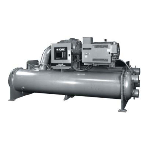
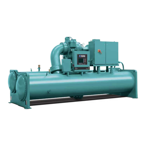
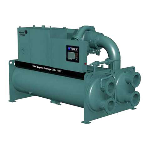
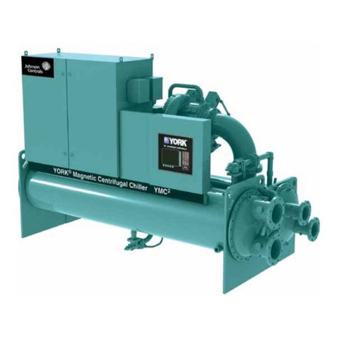
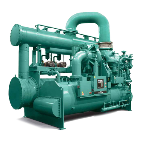
The YORK Model YMC2Chiller is commonly applied
to large air conditioning systems, but may be used on
other applications. The chiller consists of a hermetic
motor mounted to a compressor, condenser, evaporator
and variable flow control.
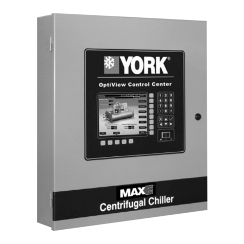
The chiller is controlled by a modern state of the art
Microcomputer Control Center that monitors its opera-
tion. The Control Center is programmed by the opera-
tor to suit job specifications. Automatic timed start-ups
and shutdowns are also programmable to suit nighttime,
weekends, and holidays. The operating status, tem-
peratures, pressures, and other information pertinent
to operation of the chiller are automatically displayed
and read on a graphic display. Other displays can be
observed by pressing the keys as labeled on the Control
Center. The chiller with the OptiViewTM Control Cen-
ter is compatible with the Variable Speed Drive.
In operation, a liquid (water or brine to be chilled)
flows through the evaporator, where boiling refrigerant
absorbs heat from the liquid. The chilled liquid is then
piped to fan coil units or other air conditioning terminal
units, where it flows through finned coils, absorbing
heat from the air. The warmed liquid is then returned to
the chiller to complete the chilled liquid circuit.
The refrigerant vapor, which is produced by the boil-
ing action in the evaporator, flows to the compressor
where the rotating impeller increases its pressure and
temperature and discharges it into the condenser. Wa-
ter flowing through the condenser tubes absorbs heat
from the refrigerant vapor, causing it to condense. The
condenser water is supplied to the chiller from an ex-
ternal source, usually a cooling tower. The condensed
refrigerant drains from the condenser into the liquid
return line, where the variable orifice meters the flow
of liquid refrigerant to the evaporator to complete the
refrigerant circuit.
The major components of a chiller are selected to
handle the required refrigerant flow at full load design
conditions. However, most systems will be called upon
to deliver full load capacity for only a relatively small
part of the time the unit is in operation. A means exists
to modulate capacity for other loads.
CAPACITY CONTROL
The speed at which the compressor rotates establishes
the pressure differential that the chiller can operate
against. As speed is reduced, the chiller power use is
reduced. At reduced capacity requirements where con-
denser pressure is also reduced, the motor speed is re-
duced as much as possible while maintaining chilled
water temperature and sufficient pressure differen-
tial. When the speed cannot be further reduced due to
pressure difference required for the specified leaving
chilled water temperature setting and available cool-
ing to the condenser, other means to reduce refriger-
ant gas flow are used to manage capacity. Compressor
models M1B-197FAA and M1B-205FAA use a device
called prerotation vanes (PRV) at the entrance to the
impeller to reduce capacity (See Figure 2). Regard-
less of chiller compressor model, the chiller also has a
mechanism called Variable Geometry Diffuser (VGD)
at the exit of the impeller that was designed to mitigate
“stall”. Stall is an effect caused by slow refrigerant gas
1
FIGURE 2 - COMPRESSOR PREROTATION VANES
LD15000


