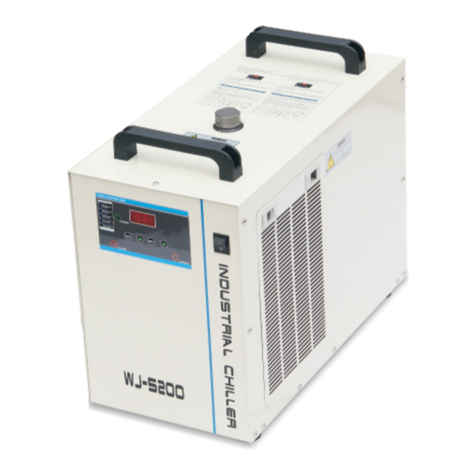
Instanta UCCH1000 User manual

Under Counter Chiller
Model: UCCH1000
INSTA ATION INFORMATION
& USER INSTRUCTIONS
Instanta Limited
Canning Road, Southport
Merseyside, PR9 7SN
Tel: 01704 501114
Fax: 01704 501115
Email: [email protected]
Website: www.instanta.com
Join us at:
www.facebook.com/instantaltd
@Instanta td
IB28a
The Professional’s Choice

ICONTENTS:
1) Transportation of Refrigeration Equipment
2) Checklist
3) Important information for installation
4) Installation instructions
5) Water dispense font
6) Mains water connection
7) Initial priming of the chiller unit
8) Set-up of water flow rate
9) Technical Specifications
10) Guarantee
Installation is straight forward but it is recommended
that this is carried out by a properly trained fitter.
1) TRANS ORTATION OF REFRIGERATION EQUI MENT:
Important: This chiller must be transported in an upright position.
As with all refrigeration systems, irreparable damage can be caused by laying the chiller on its side or
even transporting upside down.
If a chiller has been transported incorrectly, it should be placed in the correct upright position and left
for 24hours before attempting to run it. Failure to observe these precautions could seriously damage
the refrigeration system.
2) CHECKLIST:
Before starting installation, check that you have the following:
• UCCH1000 Chiller
• Water Dispense Font
• Ventilation kit (Standard-type) - use when fitting under-counter chiller unit into an enclosed space
e.g. kitchen cupboard
• Flexible water-inlet hose assembly c/w water purification filter
NOTE: An alternative ventilation kit is available from Instanta Spares (Part No: UCC/D1), for
installations within an enclosed cupboard that don’t have a void-space - see Scenario 2 (below).
3) IM ORTANT INFORMATION FOR INSTALLATION:
The Instanta UCCH1000 Dry Chiller is designed to be fitted underneath a counter-top, in close proximity
to both mains water and electrical supplies. The chiller is intended to be installed in conjunction with
the Water Dispense Font and the water purification filter…both supplied. Always site the unit in a
well-ventilated room of sufficient size (avoid small alcove-rooms with no ventilation).
When installing the UCCH1000 under-counter chiller, there are TWO very important parameters which
MUST be achieved for a correct installation and to meet the conditions of the guarantee;
1) GOOD VENTILATION & AIR-FLOW: it is essential that the unit has good air-flow which is
directed into one of the two air-intakes.
2) HEAT EX ELLED: it is essential that warm exhaust air expelled from the rear of the unit, is
directed away from the air-intake (to avoid warm air being re-circulated).
Important: Failure to provide sufficient air-flow and ventilation will seriously impair the

performance of the chiller and may cause over-heating which will invalidate the guarantee.
The UCCH1000 can be located in various locations and installed in a variety of different ways and
consequently it is impossible to provide a single, “standard” set of installation instructions suitable for
all scenarios. However, as highlighted above, it is essential that the TWO parameters; 1) good airflow/
ventilation and 2) warm air directed away from air-intake, are always achieved, wherever, or however
the unit is installed.
The UCCH1000 unit has TWO air-intake grills; the main intake is in the base of the chiller-unit and the
secondary air-intake is in the front of the unit (covered by a removable plate). If the chiller is to be sited
on a solid floor (and air-flow cannot be directed to the main air-intake), then the front-cover plate must
be removed, providing an alternative air-intake point.
The following THREE typical installation scenarios provide guidance on correct installation:
SCENARIO-1: Typical Installation – Enclosed within cupboard
In this scenario, the under-counter unit is located within an enclosed cupboard.
To achieve the requirement for adequate airflow, cold air has been directed into the under-side of the
unit via the kick-space void, using the ducting kit and Template A (supplied). The front vent-cover plate
(which covers the alternative air-intake grill) is left in-place.
The warm exhaust air expelled from the rear of the unit is directed through an opening in the back of
the cupboard-void using Template B provided (this prevents the warm air from being recirculated within
the cupboard space).
SCENARIO-2: Typical Installation – Enclosed within cupboard (No kick space or
void at back of cupboard)
UC Chiller
D.75
Ducting
air-intake
Ventilation grill in
base of cupboard
Void at back of
cupboard
(minimum of 50mm)
Use“ T EM PL AT E B”
to mark the
opening for the
exhaust air in the
back of the
cupboard-void
FRONT VENT COVER PLATE:
leave in place if vent kit and
ducting are used, as in this
diagram. Remove if vent kit is
not being used and unit is
placed on a solid floor, instead
Warm air expelled
to avoid it being
circulated within
the cupboard
space
Use“ T EM PL AT E A”
to mark position of
the opening for the
exhaust air inlet
in the base of the
cupboard
IMPORTANT:
Secure Chiller Unit in
position using small
bracket supplied,
to prevent it being
moved inadvertently
Attach inlet grill
to the kick-board
(4 screws)
Water-font fitted into
counter-top.
CHILLER
UNIT
Kick-space void
Rectangular duct
(ventilation kit)
V O ID
K I C K S PACE VOID
UC Chiller
UC Chiller
D.75
ounc
er-ftaW
.oper-ttoun
oted int fittoner-f
espac
doarthe cupb
ed withintculacir
eingoid it bvo at
elledxpm air earW
OIDV
ed within
eing
elled
(minimum of 50mm)
doarcupb
t back of
oid a
V
V
tlyenterved inadvmo
eingt it benveo prt
,et suppliedackbr
osition using smallp
nit inhiller Ue CecurS
:
ANT
T
TAN T
IMPOR
illttach inlet grA
O I DC E VAS PK I C K
oidd-voarcupb
back of the
xhaust air in thee
or theening fop
k theo mart
B
TE
A
ATE
TEMPLse “U
xhaustair in t h e
”
CHILLER
UNIT
air-in
D
CHILLER
etakair-in
tingucD
(minimum of 50mm)
s)ew(4 scr
doarick-bo the kt
illttach inlet grA
it)tion ktilaen(v
ttangular ducecR
ed on a solid floplac
eing used and unit isbnot
am.diagr
ting arduc
e in placvlea
ONTFR
doarcupb
in the base of the
xhaust air inlete
or theening fthe op
osition ofk po mart
”A
TE
A
ATE
TEMPLse “U
base of cupb
enV
ead
inst
,
, ins
or
,
ed on a solid flo
eing used and unit is
it ist kene if vvemo
R
m.
as in this
,
,
e usedting ar
it andt kene if ve in plac
TE:
A
AT
OVER PLVENT CONT
doarbase of cupb
ill intion grtilaen
oide vick-spacK

In this scenario, the under-counter unit is again located within an enclosed cupboard but this time, there
is no void-space at the back of the cupboard and the kick-space is unusable.
To achieve adequate air-flow into the unit, the alternative, front air-intake grill is utilised by removing
the front cover-plate. A cut-out is made in the front of the cupboard door, which aligns with the front air-
intake grill. With no void-space available, the warm expelled air from the back of the unit has been
ducted through the adjoining cupboard to a ventilation grill on the outside (using alternative ducting kit
not supplied – available from Instanta Spares Centre: Part No: UCC/D1). This prevents the warm
exhaust air from being recirculated within the cupboard space and therefore fulfils installation
requirements.
SCENARIO-3: Typical installation – NOT enclosed
In this scenario, the under-counter unit is located underneath a work surface but not enclosed by a
cupboard.
VIEW FROM ABOVE
WARM AIR
EXPELLED,
to avoid it being
circulated within the
cupboard space
FRONT VENT COVER.
Remove if unit is
placed on a solid
COLD AIR INLET
HOT AIR
DUCTING
UCCH1000
D.87.87D
UC
.87
CH1000UC
W FRVIE OM ABOVEW FR
OLD AIR INLEC TOLD AIR INLE
cir
ed spaccupboar
ed within thetculacir
oid it beingvo at
,EXPELLED
ARM AIR
W
WA
TINGDUC
T AIRHO
OLD AIR INLEC TOLD AIR INLE
ed spaccupboar
d baseoor/cupboar
ed on a solidplac
e if unit isvemoR
OVER.VENT CONTFR
d base
ed on a solid
OVER.
GAP TO WALL MINIMUM
OF 175mm TO ALLOW
WARM AIR TO BE
EXPELLED,
UNRESTRICTED
FRONT VENT COVER
REMOVED TO
ALLOW AIR FLOW
INTO UNIT
UCCH1000
D.88

The unit has been placed on a solid floor and the front vent-cover plate removed to allow air-flow in
through the front. The unit has been positioned at least 175mm away from the wall so there is sufficient
space at the back of the unit to allow warm exhaust air to be expelled to atmosphere.
As the installation is open-plan (not enclosed), warm air expelled will simply disperse into the room
space (providing the room is well ventilated and of sufficient size) - there should not be any need to
duct away from the unit.
4) INSTALLATION INSTRUCTIONS:
lease read the following, referring to scenario/diagram 1 (above):
If the under-counter unit is to be located within an enclosed kitchen cupboard, the standard ventilation
kit (supplied) must be fitted as per the following instructions. This allows cool air to be drawn in from a
vent in the kick-board at the front of the cupboard, and warm air is blown out through the rear panel in
the cupboard into the void between the cupboard and the wall.
NOTE: The rear panel of the cupboard should not be too close to the wall…a gap of 50mm will be
sufficient in most cases. In virtually all installations, the warm air will then be able to escape from this
area easily and no additional ventilation will be necessary. However, if the back of the cupboard is
completely sealed to the wall and there is no way for heat to escape, the chiller will not work correctly
and additional ventilation will be necessary to allow the warm air to escape (see Scenario/diagram-2
above using alternative ducting kit - not supplied).
INSTRUCTIONS (using Standard vent kit):
1) Before installation, ensure there is an electrical socket in close proximity to the intended site of
the chiller. If not it will be necessary to have one fitted by a qualified electrician.
2) Also ensure there is adequate space at the back of the cupboard and a way for the warm air to
escape…a 50mm void between the panel and the wall should be sufficient.
3) Identify the best location for the chiller, water-font and filter. Plan the connection to a water mains
supply, routing of any tubes and location of components to ensure the installation is as unobtrusive
as possible.
4) It is also necessary to ensure that the air inlet duct will not clash with any legs or other obstacles
in the cupboard kick space.
5) Using the paper TEMP ATE-A (BASE), mark the position of the chiller sides on the base of the
cupboard, and the position of the opening for the air-inlet. Using template B, mark the opening for
the exhaust air in the back of the cabinet.
6) Referring to the drawing, mark out the position of the opening in the kick-board and cut out the air
inlet hole in the kick board.
NOTE: Dimensions are measured from the left-side and bottom of the chiller (see drawing). The
left side of the chiller should have been marked onto the base (see 5, above).
7) Insert the right-angled spigot into the hole in the base of the cabinet.
8) Fit the length of rectangular duct through the cut-out in the kick-board and into the spigot. Ensure
it is fully engaged into the socket and mark the ducting where it protrudes from the kick board.
Remove the duct and cut to length.
9) Refit the rectangular duct, and attach the outlet grill to the kick-board using 4 screws. This will
retain the duct in position.
10) Now place the chiller unit in position over the air inlet opening, ensuring the outlet grill on the
back of the machine aligns with the back of the cabinet.
Important: The ventilation openings must align with the cut-outs in the cabinet to ensure reliable
operation of the chiller, and the chiller should be fixed in position to prevent the chiller being
moved inadvertently.
Failure to provide sufficient ventilation and air-flow will seriously impair the performance of the
chiller and may cause overheating which will invalidate the guarantee.

5) WATER DIS ENSE FONT:
a) Identify the best location for the font, but take--- into consideration the final position of the under
counter chiller unit and filter. Although we recommend that the font is located directly above the
under-counter chiller (shortest water-path), if this is not possible there is some degree of flexibility
and the font can be positioned up to 0.75metre either side of it.
NOTE: We recommend that the chiller unit is removed from its location until the counter
top water font has been installed, giving more room to work within the cupboard space
and also avoiding debris from cutting of holes in the counter-top dropping onto it.
b) Cut holes in counter using paper template provided – for hole positions.
c) Place water font into position using a thin bead of silicone sealant or similar to form a seal between
the underside of the font and the counter-top.
d) Secure water font to counter using 2 x M8 nuts and washers (supplied)
IM ORTANT: Ensure electrical plug/lead from font is not trapped when fixing water font to
counter top.
e) Fit drain-kit (supplied) into drip-tray. Using suitable flexible tube, direct to a drain/waste.
f) Re-position the under-counter chiller unit inside the cupboard again, aligning it with the ventilation
openings. Fix in position to prevent the chiller from being moved inadvertently.
To do this, secure in position using one of the fixing brackets supplied. oosen the chiller screw
at the front-centre, near the base, insert the bracket and replace screw. Then secure the bracket
by driving the self tapping screw to the cabinet base.
g) Cut the blue water-feed tube to size (if too long) and push into the “CHI ED WATER OUT”
coupling.
It is advisable to fit insulation to the tube between the font and the chiller unit.
h) Plug electrical lead into socket on top of chiller unit (marked; “FONT CONTRO ”).
Important: The ventilation openings must align with the cut-outs in the cabinet to ensure reliable
operation of the chiller, and the chiller should be fixed in position to prevent the chiller being moved
inadvertently.
Failure to provide sufficient ventilation and air-flow will seriously impair the performance of the chiller
and may cause overheating which will invalidate the guarantee.
6). MAINS WATER CONNECTION:
Make mains water connection to the chiller unit. It is essential that you use the WRAS approved, food
quality hose assembly c/w water purification filter.
IM ORTANT: Flush approximately 10 litres of water through the hose assembly BEFORE connecting
it to the chiller unit. This will flush any carbon particles out of the cartridge filter.
NOTE: If your mains water pressure exceeds 4 bar (58psi), a suitable pressure reduction valve will
need to be fitted to the water supply to bring it to a level that the machine can cope with.
IM ORTANT: We strongly recommend the fitting of a water block (flood protection).
7) INITIAL RIMING OF THE CHILLER UNIT:
a) With the mains water supply connected, plug chiller unit into a 13amp socket and switch on. The
compressor and fan will start up and the font push-button will illuminate blue.
b) Immediately after the chiller unit has been switched on, place a container under the outlet and

press the illuminated push-button to energise the water inlet valve, priming the unit with water.
c) Keep finger on the push-button until water begins to flow from the font-outlet. Continue to push
button until approximately 3 litres of water have passed through the chiller unit and flushed the
system out.
IM ORTANT: If the font push-button does not illuminate and allow water into the chiller unit, switch off
immediately. Check that the font-control lead is securely plugged into the socket on the chiller unit and
water supply is turned on. If all OK but problem persists, contact Instanta technical department.
After approximately 5 minutes, the fan and compressor will turn off indicating the fridge has
reached its normal operating temperature and is ready for use.
8) SETTING THE CORRECT WATER FLOW RATE:
The water pressure and flow rate have been factory set, however on-site adjustment may be necessary.
The water flow-rate adjustment knob is on top of the chiller unit, at the back.
To adjust; pull valve adjuster upwards and turn clockwise to increase pressure/flow rate and anti-
clockwise to reduce.
As a guide, a small cup (180ml) should take approximately 5 seconds to dispense.
NOTE: If the flow-rate is faster than this, the water will pass through the cooling block too quickly and
the drink may not be as cool as it should be.
9). TECHNICAL S ECIFICATIONS:
Under-counter unit, outer casing is constructed from stainless steel. Water font is constructed from
stainless steel and chrome-plated brass.
Operating arameters:
Rated Voltage: 230V AC
Rated Current: 1.2A
Minimum Ambient Temp: 5°C
Maximum Ambient Temp: 30°C
Water Pressure (Min): 1.0bar (15psi)
Water Pressure (Max): 4.0bar (58psi)
Dimensions & Weight of Under-counter Chiller unit:
Height: 390mm
Width: 180mm
Depth: 340mm
Weight: 7.0kg (empty)
Refrigeration System:
Refrigeration type & charge: R134a 85g
Cooling Power: 185W
Energy Consumption: 18.3 Wh/
10) GUARANTEE:
The UCCH1000 has a twelve month parts and labour guarantee. The guarantee covers faults in
manufacture but excludes problems caused by misuse or incorrect installation. The filter cartridge should
be changed every six months.
Table of contents