BIFFI ELBS-20 User manual
Installation, Operation and Maintenance Manual
MAN712 Rev. 9
June 2021
Bif ELBS-20
Electronic Line Break System 20
Copyright © Biffi. The information in this document is subject to change without notice. Updated data sheets can be obtained from our website www.biffi.it or from your nearest Biffi Center:
Biffi Italia s.r.l. - Strada Biffi 165, 29017 Fiorenzuola d'Arda (PC) – Italy PH: +39 0523 944 411 – biffi_italia@biffi.it

Revision Details
June 2021
Installation, Operation and Maintenance Manual
MAN712 Rev. 9
Revision Details
Revision Details
Rev. Date Description Prepared Checked Approved
9 June 2021 General update (Migration to new template)
8 September 2020 Eighth Issue Piacenti Doglio
7 July 2016 Seventh Issue Battaglia Vigliano
6 October 2015 Sixth Issue Battaglia Vigliano
5 December 2014 Fifth Issue Battaglia Vigliano
4 August 2013 Fourth Issue Battaglia Vigliano
3 July 2013 Third Issue Battaglia Vigliano
2 May 2013 Second Issue Battaglia Vigliano
1 April 2013 Second Issue Battaglia Vigliano
0 February 2013 First Issue Battaglia Vigliano

i
Installation, Operation and Maintenance Manual
MAN712 Rev. 9
Table of Contents
June 2021
Table of Contents
Table of Contents
Section 1: Reference Document
Reference Document...............................................................................................1
Section 2: General Safety Instructions
2.1 Manufacturer................................................................................................ 2
2.2 Intended Use................................................................................................. 2
2.3 Terms and Conditions ................................................................................... 3
2.4 Manufacturer’s Liability................................................................................. 3
2.5 Applicable Standards and Regulations........................................................... 3
Section 3: Storage
Storage....................................................................................................................4
Section 4: Device Description
4.1 Identication of the Main Parts...................................................................... 7
4.2 Electronic Cards ........................................................................................... 8
4.2.1 Electronic Cards - Pinout .................................................................... 8
4.2.2 Electronic Card – Details (Jumpers, Fuses,
Push-Buttons, Batteries).............................................................................. 10
4.3 Technical Specications .............................................................................. 13
4.4 Overall Dimensions (EJB51 Cabinet) ............................................................ 16
4.5 Options....................................................................................................... 16
Section 5: Working Principle and
Detailed Description
5.1 Working Principle........................................................................................ 17
5.1.1 Table of Operating Modes................................................................. 22
5.1.2 Details of the Valve Control Operating Mode.................................... 23
5.1.3 Examples of Pressure Drop Rate Control ........................................... 25
5.2 Detailed Description ................................................................................... 26
5.2.1 Conguration-Managing Interfaces.................................................. 26
5.2.2 Power Supply (External – Battery Pack)............................................. 28
5.2.3 Analog Output (Pressure or Position Retransmission) ....................... 31
5.2.4 Digital Input ..................................................................................... 31
5.2.5 Digital Output .................................................................................. 31
5.2.6 Analog Input - Pressure Transducer................................................... 32
5.2.7 Analog Input - Position Sensor.......................................................... 32
5.2.8 SOV Control Outputs........................................................................ 32
5.2.9 MODBUS RTU................................................................................... 35
Section 6: Conguration Parameters
6.1 Precision of the Analog Inputs..................................................................... 51
6.2 Table of Digital Outputs Functions .............................................................. 52
6.3 Table of Digital Inputs Functions.................................................................. 53
6.4 Tables of the Alarms and Warnings.............................................................. 54

ii
Table of Contents
June 2021
Installation, Operation and Maintenance Manual
MAN712 Rev. 9
Table of Contents
Section 7: Local Operator Interface
7.1 Info Bar ....................................................................................................... 57
7.2 Normal Mode Menu .................................................................................... 58
7.3 Login Menu ................................................................................................. 59
7.4 View Mode and Setup Mode Menus ............................................................ 60
7.4.1 View Graph of the Setup/View Mode Menus..................................... 60
7.4.2 Push-buttons Functionality .............................................................. 67
Section 8: Modbus RTU Interface
8.1 Modbus Standard References ...................................................................... 68
8.2 Modbus Communication Features............................................................... 68
8.3 Modbus Wirings.......................................................................................... 69
8.3.1 Modbus RS485 Transmission Mode .................................................. 69
8.4 Modbus Function Description ..................................................................... 71
8.4.1 Function Code 03 (0x03) Read Holding Registers ............................. 72
8.4.2 Function Code 06 (0x06) Write Single Register................................. 73
8.4.3 Function Code 16 (0x10) Write Multiple Registers ............................ 74
8.4.4 Function Code 72 (0x48) Read Event Data ........................................ 75
8.4.5 Function Code 101 (0x65) Read Alarms and Warnings Logs.............. 77
8.4.6 Exception Codes............................................................................... 79
8.5 Holding Registers Map ................................................................................ 80
Section 9: Typical Connections
9.1 Signals Description...................................................................................... 89
9.2 Typical Connections Example...................................................................... 93
9.2.1 Example 1 – Typical Connection ....................................................... 93
9.2.2 Example 2 – Typical Connection ....................................................... 95
Section 10: Installation – Start-Up
10.1 Installation in Ambient with Explosive Dusts................................................ 98
10.2 Checks to be Performed Before Installation................................................. 98
10.3 Battery Pack First Connection ..................................................................... 98
10.4 Cables and Electrical Connections............................................................... 99
10.4.1 Cables Connection ........................................................................... 99
10.4.2 Cables Requirements – EMC Protection.......................................... 100
10.4.3 Wires Dimensions .......................................................................... 101
10.4.4 Unused entries ............................................................................... 101
10.5 Start-up Procedure.................................................................................... 101
10.6 Position Limits Calibration (Optional)........................................................ 103

iii
Installation, Operation and Maintenance Manual
MAN712 Rev. 9
Table of Contents
June 2021
Table of Contents
Section 11: Restore Valve Control
Restore Valve Control...........................................................................................104
Section 12: Battery Maintenance and First Installation
Battery Maintenance and First Installation..........................................................105
Section 13: Parts List
13.1 General Assembly ..................................................................................... 114
13.2 General Assembly ..................................................................................... 115
Section 14: Decommissioning
Decommissioning................................................................................................116
Section 15: Troubleshooting
Troubleshooting...................................................................................................117
Section 16: Ordering Table
Ordering Table......................................................................................................119

Installation, Operation and Maintenance Manual
MAN712 Rev. 9
Notes
June 2021
This page is intentionally left blank

Installation, Operation and Maintenance Manual
MAN712 Rev. 9 June 2021
Reference Document 1
Section 1: Reference Document
Section 1: Reference Document
[1]: MDE226 - “ELBS-20 Bif Assistant User Manual”.

June 2021
Installation, Operation and Maintenance Manual
MAN712 Rev. 9
General Safety Instructions2
Section 2: General Safety Instructions
Section 2: General Safety Instructions
2.1 Manufacturer
Manufacturer with respect to Machinery Directive 2006/42/EC is Bif Italia, as specied on
the machinery label.
2.2 Intended Use
The ELBS-20 electronic device covered in this Installation, Operation and Maintenance
Manual is designed to monitor the pipeline integrity. The ELBS-20 continuously measures
the pressure in the line, it can store the pipeline data (pressure trend) and in case of failure
it can send a command to the actuator to stroke the line valve to the fail-safe position.
Bif Italia will not be liable for any possible damage or physical injury resulting from use
in other than the designated applications or by lack of care during installation, operation,
adjustment and maintenance of the machine. Such risks lie entirely with the user.
Depending on the specic working conditions, additional precautions may be requested.
Considering that Bif Italia has no direct control over particular applications, operation or
maintenance conditions, it is the operator’s responsibility to comply with all applicable
safety rules. Please inform Bif Italia urgently if you face unsafe situations not described
in this IOM. It is the sole responsibility of the operator to ensure that the local health and
safety regulations are adhered to.
! WARNING
It is assumed that the installation, setting, commissioning, maintenance and repair works
are carried out by qualied personnel and checked by responsible specialists.
! WARNING
Any repair work other than the operations outlines in this IOM will be strictly reserved to
qualied Bif Italia personnel or to personnel directly authorised by the company itself.
ELBS-20 devices are designed in accordance with the applicable International Rules and
Specications, but the following Regulations must be observed in any case:
• The general and safety regulations.
• The plant specic regulations and requirements.
• The proper use of personal and protective devices (glasses, clothing, gloves, etc.).
• The proper use of tools, lifting and transport equipment.
! WARNING
The electronic parts of the ELBS-20 and all the options can be damaged by a discharge
of static electricity. Before you start, touch a grounded metal surface to discharge any
static electricity.

Installation, Operation and Maintenance Manual
MAN712 Rev. 9 June 2021
General Safety Instructions 3
Section 2: General Safety Instructions
2.3 Terms and Conditions
Bif Italia guarantees each single product to be free from defects and to conform to current
goods specications. The warranty period is one year from the date of installation by the
rst user, or eighteen months from the date of shipment to the rst user, whichever occurs
rst. No warranty is given for products which have been subject to improper storage,
improper installation, misuse, or corrosion, or which have been modied or repaired by
unauthorised personnel. Repair work due to improper use will be charged at standard rates.
2.4 Manufacturer’s Liability
Bif Italia declines all liability in the event of:
• Use of the device in contravention of local safety at work legislation.
• Incorrect installation, disregard or incorrect application of the instructions
provided on the device nameplate and in this manual.
• Modications without Bif’s authorisation.
• Work done on the unit by unqualied or unsuitable persons.
2.5 Applicable Standards and Regulations
EN ISO 12100-1: Safety of machinery - Basic concepts, general
principles for design.
Part 1-Basic terminology, methodology.
EN ISO 12100-1: Safety of machinery - Basic concepts, general
principles for design.
Part 2-Technical principles and specication.
EN 60204/1: Electrical equipment of industrial machines.
Part 1- General requirements.
2006/42/EC: Machinery directive.
2004/108/EC: EMC Directive
94/9/EC: ATEX Directive
2006/95/EC: Low Voltage Directive
IEC 60068-2-6, IEC 60068-2-57: Vibration Test

June 2021
Installation, Operation and Maintenance Manual
MAN712 Rev. 9
Storage4
Section 3: Storage
Section 3: Storage
NOTICE
Not performing the following procedures will invalidate the product guarantee.
All the ELBS-20s leave the factory in perfect condition. When mounted together with
the actuator they are guaranteed by the actuator test certicate; in other cases, they are
guaranteed by an individual certicate. In order to maintain these characteristics until the
ELBS-20 is installed on site, proper attention must be observed for preservation during the
storage period.
The standard plastic plugs used to protect the cable entries during the transport are not
waterproof; they just prevent the entry of undesired objects during transport: during the
storage it is recommended to replace them with waterproof version.
In any case storage is recommended in close ambient without excessive humidity.
If the battery cells are included, the storage temperature must meet the battery cell
specications (storage).

Installation, Operation and Maintenance Manual
MAN712 Rev. 9 June 2021
Device Description
Section 4: Device Description
5
Section 4: Device Description
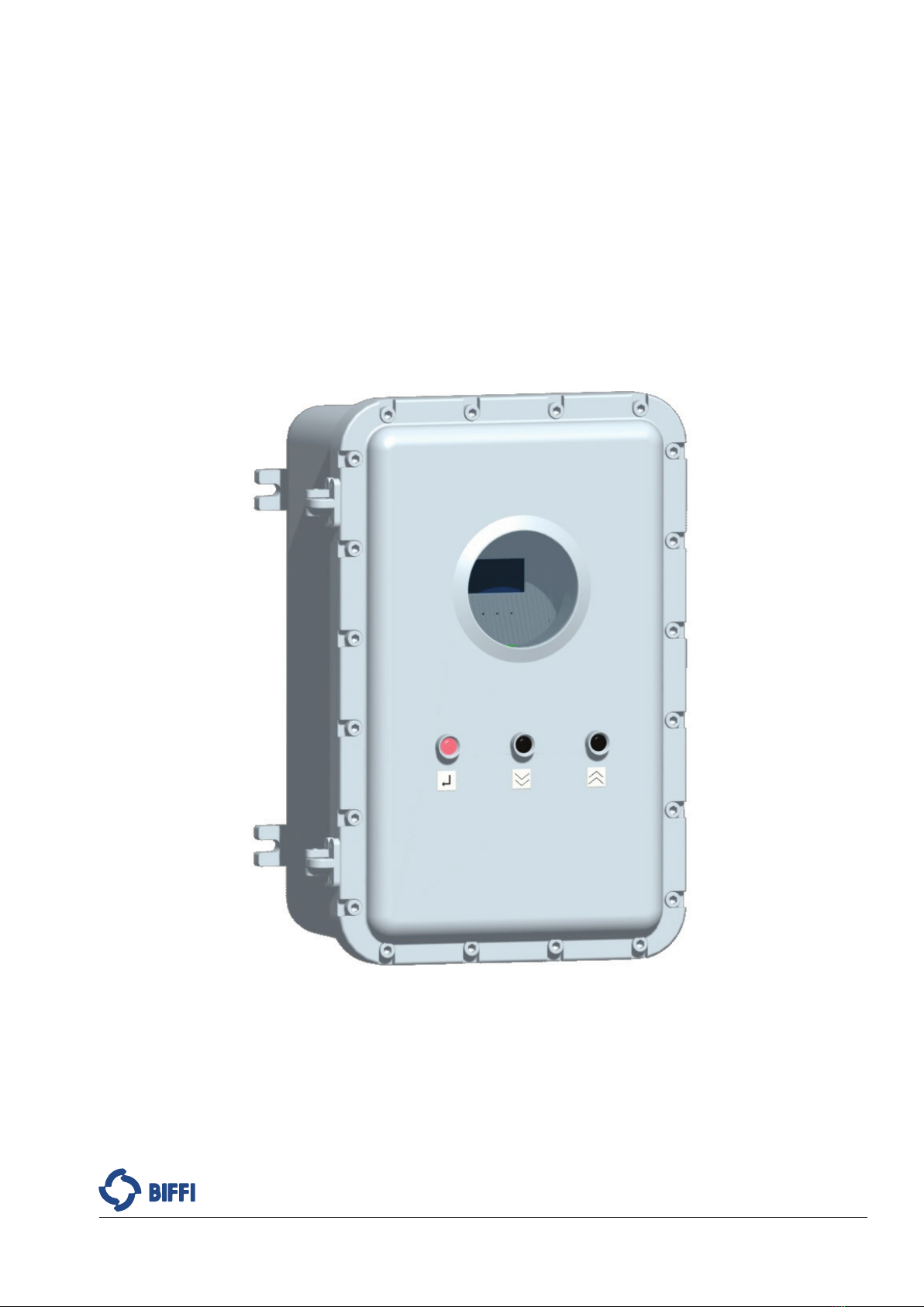
General Description
The Line Break Detection System type ELBS-20 is an electronic equipment, developed by
Bif, for monitoring the pipeline integrity. The ELBS-20 measures, with a settable time
interval, the pressure in the line, it can store the pipeline data (pressure trend) and in case
of failure it can send a command to the actuator to stroke the line valve to the fail-safe
position (Safety Action).
The ELBS-20 was especially engineered for “ON FIELD” service; it means capability of
working in the severest ambient conditions, as wide operating temperature range,
vibrations, explosive atmosphere, etc.
Conguration-Managing Interfaces
The ELBS-20 is provided with a powerful local operator interface, made of one 128x64
graphical OLED display and 3 push-buttons that allow entering the conguration data and
visualizing the values of variables or the status of the device.
Moreover an RS232, an RS485 and a Bluetooth serial communication ports are provided
for the connection with the “Bif Assistant” software tool (see [1] for details), to carry out
parameter conguration, or variables visualization or to download the recorded event data
for further analysis of pipeline behavior.
Power Supply
The ELBS-20 accepts two different sources of power supplies:
• External Power Supply from 19.2 V DC to 57.6 V DC (24 V DC -20% to 48 V DC
to +20%).
• Battery Pack power supply: 7.2 V DC (lithium batteries).
The two power supplies can be applied one or both per time.
When both the power supplies are present, the Battery Pack works as back-up of the
External Power Supply.
The ELBS-20 monitors the status of the External Power Supply and the status of the Battery
Pack Power Supply.
Battery Packs
The Battery Pack Card of the ELBS-20 provides two independent battery packs
(Default and Auxiliary) with dedicated protection circuit (diodes and fuses).
Each battery pack is composed by four Li-SOCl2 size D cells (parallel of two cells in series).
Analog Inputs (Pressure and Position Sensors)
The ELBS-20 is provided with two (Pressure and Position) congurable
(0 - 20 mA or 4 - 20 mA) analog inputs (AI). The ELBS-20 supplies a 14.5 V DC voltage to
the sensors.
Digital Inputs (Opto-isolated)
The ELBS-20 is provided with three congurable opto-isolated Digital Inputs (DI).

June 2021
Installation, Operation and Maintenance Manual
MAN712 Rev. 9
Device Description
Section 4: Device Description
6
Analog Output
The ELBS-20 is provided with a congurable 4 - 20 mA analog output (AO).
The AO can be used for the retransmission of the Pressure or Position measured by the AIs.
The AO can accept an external 24 V DC power supply or internally generates the 24 V DC,
necessary for the 4 - 20 mA signal.
Digital Outputs (Relay contacts).
The ELBS-20 is provided with 7 Digital Outputs (DO):
• 6x SPST latching relays contacts
• 1x SPDT single side stable relay contacts
Modbus RTU
The ELBS-20 is provided with a MODBUS RTU (RS485) bus interface.
SOV Control Outputs
The ELBS-20 is provided with the following outputs dedicated to the Solenoid
Valve Control:
• 2x 24 V DC - 100 mA isolated outputs (SVC)
• 2x SPDT single side stable relays contacts (RL)
The SOV Control Outputs are used for managing one or more external SOVs in order to
send a command to the actuator to stroke the line valve to the fail-safe position
(Safety Action).
The SOV Control Outputs can be used also to drive a contactor of an electrical actuator
(no SOVs required) to stroke the line valve to the fail-safe position.
The ELBS-20 provides also the possibility to use DO1 and DO2 as SOVs Control Outputs.
Integrity Check of the Safety Action Electrical Circuit
The ELBS-20 allows monitoring the status of the Safety Action Electrical Circuits
(dedicated SOV Control Output + Coil + Wiring Connection).
Auto-diagnostic
The ELBS-20 monitors the status of the power supply sources, of the internal voltages and
of the Analog Inputs circuits.
Installation, Operation and Maintenance Manual
MAN712 Rev. 9 June 2021
Device Description
Section 4: Device Description
7
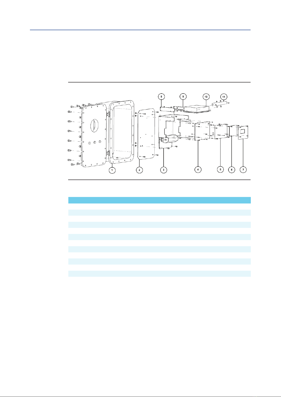
4.1 Identication of the Main Parts
In this section only the main parts of the ELBS-20 are shown. Refer to Section 13 for a full
list of the ELBS-20 parts.
Figure 1
Table 1.
Pos. Description Qty
1 CABINET MOD. EJB51 (*) 1
2 EJB51 INTERNAL PLATE (*) 1
3 ELBS-20 CARDS BRACKET 1
4 PROCESS CARD 1
5 INTERFACES CARD 1
6 DISPLAY/BLUETOOTH CARD 1
7 DISPLAY/BLUETOOTH CARD MASK 1
8 BATTERY PACK LEFT BRACKET 1
9 BATTERY PACK RIGHT BRACKET 1
10 BATTERY PACK CARD (opt.) 1
10.1 BATTERY CELLS (opt.) 4 or 8
11 BATTERY PACK FRONTAL EXTRACTOR 1
NOTE:
(*) The EJB51 cabinet is normally provided when the following ordering options are selected:
Cabinet Material = A and Cabinet Electrical Certication = B (see Section 16 for details).

June 2021
Installation, Operation and Maintenance Manual
MAN712 Rev. 9
Device Description
Section 4: Device Description
8
4.2 Electronic Cards
4.2.1 Electronic Cards - Pinout
The gure below shows the 292ELBS100 block that is composed by the following
electronic cards:
• 492LBDS100: DISPLAY/BLUETOOTH CARD
• 492LBIN100: INTERFACES CARD
• 492LBPR100: PROCESS CARD
Figure 2

Installation, Operation and Maintenance Manual
MAN712 Rev. 9 June 2021
Device Description
Section 4: Device Description
9
The gure below shows the 492LBBP100 – BATTERY PACK CARD.
Figure 3
Battery Pack
Default
7.2 V DC
EARTH CABLE
(optional)
Battery Pack
Auxiliary
7.2 V DC
492LBBP100 - BATTERY PACK CARD
June 2021
Installation, Operation and Maintenance Manual
MAN712 Rev. 9
Device Description
Section 4: Device Description
10
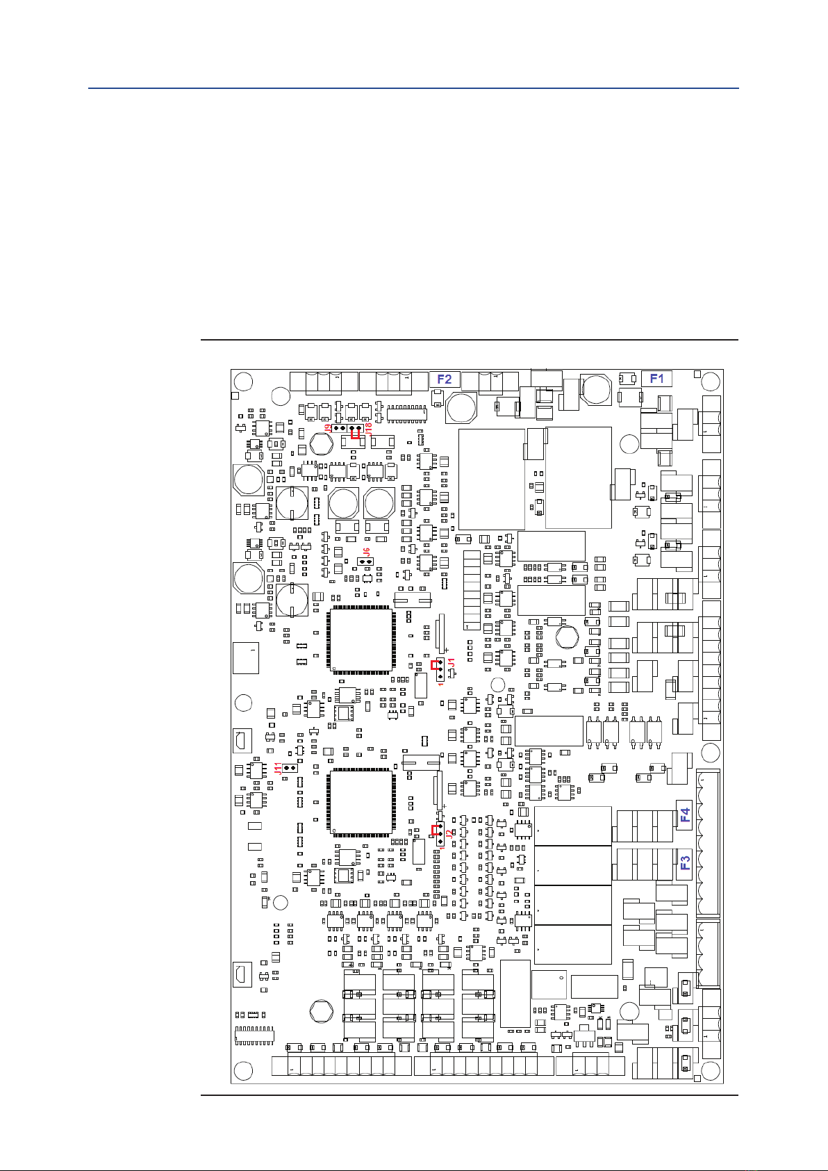
4.2.2 Electronic Card – Details (Jumpers, Fuses,
Push-Buttons, Batteries)
The gure below shows the Jumper Settings and the Fuses position of the Process Card.
The Jumpers of the Process Card (Figure below) must be set as follows:
• J18: close
• J9, J11: open
• J1, J2: 2-3 close
Figure 4 Process Card
Installation, Operation and Maintenance Manual
MAN712 Rev. 9 June 2021
Device Description
Section 4: Device Description
11
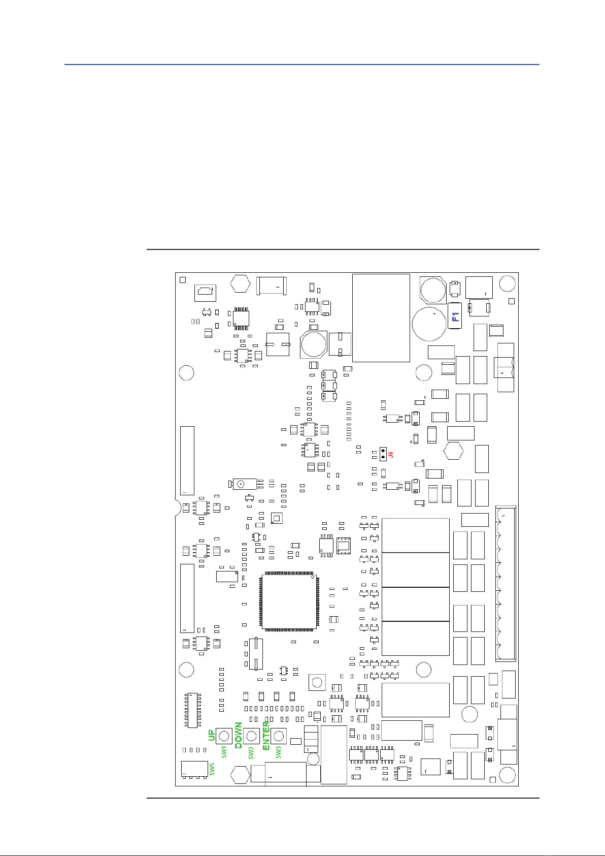
The gure below shows the Jumper Settings, the Fuse position and the Emergency
Push-buttons of the Interfaces Card.
The Jumpers of the Interfaces Card (Figure below) must be set as follows:
• J6: open
The Emergency push-buttons are:
• SW1 – UP
• SW2 – DOWN
• SW3 – ENTER
Figure 5 Interfaces Card
June 2021
Installation, Operation and Maintenance Manual
MAN712 Rev. 9
Device Description
Section 4: Device Description
12
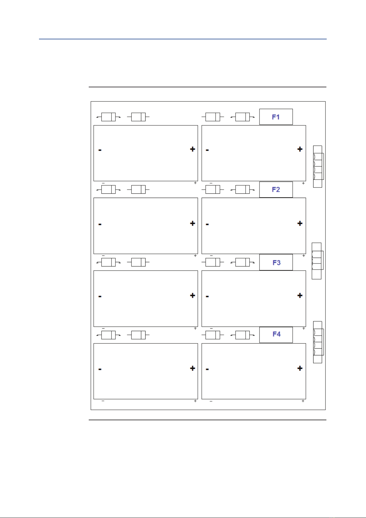
The gure below shows the Fuses position and the Battery Packs polarity of the Battery
Pack Card.
Figure 6 Battery Pack Card
BP1
BATTERY PACK DEFAULT
BP2
BATTERY PACK DEFAULT
BP3
BATTERY PACK DEFAULT
BP4
BATTERY PACK DEFAULT
BP5
BATTERY PACK AUXILIARY
BP6
BATTERY PACK AUXILIARY
BP5
BATTERY PACK AUXILIARY
BP6
BATTERY PACK AUXILIARY

Installation, Operation and Maintenance Manual
MAN712 Rev. 9 June 2021
Device Description
Section 4: Device Description
13
4.3 Technical Specications
Table 2.
External Power Supply
Supply Voltage Range 19.2 V DC - 57.6 V DC
(24 V DC -20% - 48 V DC +20%)
Std Current Consumption without sampling and
display ON (Sleep Mode or during Safety Action) (1) 70 mA - 24 V DC, 40 mA - 48 V DC
Std Current Consumption during sampling (2) 135 mA - 24 V DC, 65 mA - 48 V DC
Additional RL1 Current Consumption 20 mA - 24 V DC, 10 mA - 48 V DC
Additional RL2 Current Consumption 20 mA - 24 V DC, 10 mA - 48 V DC
Additional SVC2 Current Consumption
(100 mA Output) 200 mA - 24 V DC, 100 mA - 48 V DC
Additional AO Current Consumption (3) 60 mA - 24 V DC, 30 mA - 48 V DC
Additional MODBUS Current Consumption 20 mA - 24 V DC, 10 mA - 48 V DC
Additional RS485 Current Consumption 20 mA - 24 V DC, 10 mA - 48 V DC
Additional Bluetooth Current Consumption 20 mA - 24 V DC, 10 mA - 48 V DC
Maximum Current Consumption (4) 570 mA - 24 V DC, 290 mA - 48 V DC
Galvanic Insulation from Logic Yes
Battery Pack Power Supply
Battery Pack Nominal Supply Voltage 7.2 V DC
Single Cell Nominal Voltage 3.6 V DC
Single Cell Nominal Capacity 13.0 Ah or higher
Single Cell raccomended continuos current 1800 mA or higher
Single Cell raccomended operating temperature from -55 °C to +85 °C or wider
Battery cell type Li-SOCl2
Interval of Battery Pack replacement (5) max. 1 year (without Auxiliary Battery Pack)
max. 2 years (with Auxiliary Battery Pack)
Analog Input (Pressure and Position Sensors)
Pressure Range 10 – 1000 bar
Sensor Signal Output 4 - 20 mA or 0 - 20 mA (2 or 3 wires)
Supply Voltage (to each sensor) 14.3 – 14.8 V DC (6)
Supply Current (to each sensor) up to 25 mA
Internal Resistor (AI1 – Pressure Sensor) 119 ohm
Internal Resistor (AI2 – position Sensor) 102 ohm
Sensor Set-up Time max. 10 ms
Galvanic Insulation from Logic Yes
Digital Inputs
Allowed Voltage (”C” and “24/48” contacts) 19.2 - 57.6 V AC/V DC (24 -20% - 48 +20%)
Current Consumption (”C” and “24/48” contacts) min. 2.0 mA - max.11 mA
Allowed Voltage (“C” and “110” contacts) 99 – 132 V AC/V DC (110 -10% - 120 +10%)
Current Consumption (“C” and “110” contacts) min. 2.3 mA – max. 3.3 mA
Galvanic Insulation from Logic Yes

June 2021
Installation, Operation and Maintenance Manual
MAN712 Rev. 9
Device Description
Section 4: Device Description
14
Digital Outputs (SPST and DPST Relay Contacts)
Maximum allowed Voltage up to 120 V AC ± 10% and up to
110 V DC ± 10%
Maximum switching power
(resistive load)
up to 1 A – 120 V AC
up to 1 A – 30 V DC
up to 1 A – 48 V DC
up to 0.15 – 110 V DC
Galvanic Insulation from Logic Yes
Analog Output
Feedback Signal Pressure or Position
Output Current Range 4 - 20 mA
Maximum Load (cable+resistor) 300 ohm
Internal Power Supply Voltage 24 V DC
External Power Supply Voltage 21.6 - 26.4 V DC – max 25 mA
Galvanic Insulation from Logic Yes
SOV Control Outputs (RL1 and RL2)
Maximum allowed Voltage up to 120 V AC ± 10% and up to
110 V DC ± 10%
Maximum switching power
up to 1 A – 120 V AC
up to 1 A – 30 V DC
up to 1 A – 48 V DC
up to 0.15 – 110 V DC
Galvanic Insulation from Logic Yes
SOV Control Outputs (SVC1 and SVC2)
Output Voltage 22.5 – 24.2 V DC
Maximum Output Current 100 mA
Galvanic Insulation from Logic Yes
MODBUS RTU
Transmission Technology RS485
Baud rate (congurable) 600, 1200, 2400, 4800, 9600, 19200, 38400 bps
Parity Bit (congurable) Even, Odd, None
Stop Bit (according to Parity Bit) 1, 2
Galvanic Insulation from Logic Yes
RS485 (Conguration Port)
Baud rate 19200 bps
Parity Bit Even
Stop Bit 1
Hardware ow control Off
Galvanic Insulation from Logic Yes
Distance (cable length) (7) Max. 1000 meters
Table of contents


