manuals.online logo
Brands
  1. Home
  2. •
  3. Brands
  4. •
  5. In-situ
  6. •
  7. Measuring Instrument
  8. •
  9. In-situ Rugged TROLL 100 User manual

In-situ Rugged TROLL 100 User manual

0091332 | Rev. 006 | 09/2013
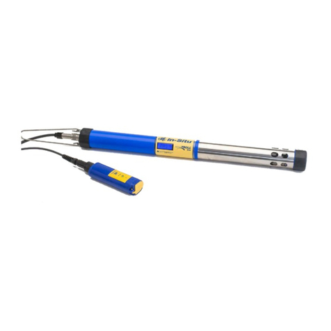
Rugged TROLL®100 and 200 and Rugged
BaroTROLL Instruments
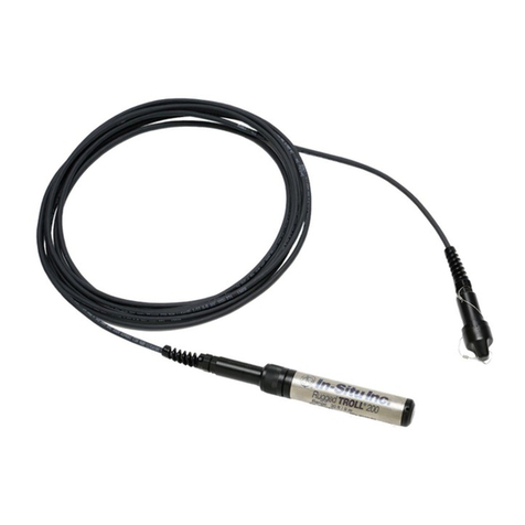
The Rugged TROLL 100 and 200 instruments are
designed to measure pressure, level, and temperature in
natural groundwater and surface water. They also can be
used at industrial sites, landfills, and other installations.
Both instruments have completely sealed housings that
contain an absolute (non-vented) pressure sensor,
temperature sensor, real-time clock, microprocessor,
lithium battery, and internal memory.
The Rugged TROLL 100 is designed to hang by a
backshell hanger from a suspension wire. The Rugged
TROLL 200 can utilize the backshell hanger or can
connect to a cable for easy top-of-well RS485
communications via RuggedReader Handheld PC or
laptop PC. Additionally, Rugged TROLL 200 cables with
stripped-and-tinned cable ends can communicate with
data loggers, TROLL Link Telemetry Systems, or PLC
devices via RS485 or SDI-12.
Rugged BaroTROLL Overview
The Rugged BaroTROLL measures and logs barometric
pressure and temperature in air. This data is used to
correct the Rugged TROLL 100 and 200 data by
compensating for barometric pressure effects during the
course of a log.
Communication Accessories
lUSB or RS232 docking station for the Rugged
TROLL 100, 200, and Rugged BaroTROLL
Instruments.
lUSB or RS232 Rugged TROLL Com for the Rugged
TROLL 200 and Rugged BaroTROLL Instruments
lWin-Situ 5 Software for programming and
downloading
lOptional software: Win-Situ Baro Merge for
barometric compensation; Win-Situ Mobile for the
RuggedReader Handheld PC; Win-Situ Sync to
transfer downloaded data logs from a
RuggedReader to a laptop or desktop PC; Software
Manager to check for updates
Other Accessories
Rugged TROLL 100
lSuspension cable
lRuggedReader Handheld PC
lRugged BaroTROLL for logging barometric
pressure data
Rugged TROLL 200
lSuspension cable
lRuggedReader Handheld PC
lRugged BaroTROLL for logging barometric
pressure data
lSDI-12 compatible cable with stripped-and-tinned
uphole termination
lRS485 compatible cable with stripped-and-tinned
uphole termination
lRS485 top-of-well cable
lRugged TROLL 200 cable suspension kit (Use this
kit to create a weight-bearing loop capable of
suspending up to 45.5 kg (100 lbs.) of cable and
instrument.)
Getting Started
You will need the following items.
lRugged TROLL 100 or 200 instrument
lRugged BaroTROLL (optional)
lUSB or RS232 docking station (The RS232 model is
needed for connection to a RuggedReader
Handheld PC and the Rugged BaroTROLL.)
lRugged TROLL Com (for Rugged TROLL 200 and
Rugged BaroTROLL).
Install Software
Install the following software from the In-Situ Software CD
or from www.in-situ.com.
Win-Situ 5 Software
1. Click the Win-Situ 5 link and follow the installation
instructions.
2. Make sure that you select the option to "Install USB
Drivers."
Win-Situ Mobile Software for the RuggedReader
Handheld PC
1. Click the Win-Situ Mobile link and follow the instructions
to install Win-Situ Software Manager, which checks for
software updates and transfers data.
2. If you are using Windows XP operating system, install
ActiveSync 4.5 or higher. If you are using Windows
Vista, Windows 7, or Windows 8, install Windows Mobile
Device Center software in order to communicate with
the RuggedReader Handheld PC.
3. Win-Situ Mobile is probably already installed on the
RuggedReader. If you need to install Win-Situ Mobile,
connect the RuggedReader to the PC via USB to serial
cable, establish a connection via ActiveSync, open the
Win-Situ Software Manager, click Win-Situ Mobile, click
Install. Make sure you have your In-Situ Software
License Certificate available.
Win-Situ Baro Merge Software
Install Baro Merge Software if you plan to post-correct
level data to compensate for barometric pressure.
Win-Situ Sync Software
Install Win-Situ Sync if you want to automatically transfer
downloaded log files from a RuggedReader to a PC.
Connect to the Rugged TROLL Docking Station
The docking station is intended for use with the Rugged
TROLL 100, 200 and Rugged BaroTROLL Instruments
that are not deployed with a communication cable. Once
connected, you can program the instrument, view
readings, and download the data.
1. Unscrew and remove the hanger from the instrument.
The hanger is the only removable part of the
instrument. Do not attempt to take the
instrument apart. There are no user-
serviceable parts in the instrument.
2. Invert the instrument. Align the notch on the instrument
with the tab on the rim of the docking station. This will
ensure that the pins are aligned to enable
communication.
3. Place the instrument into the docking station.
4. Connect the docking station to a computer.
Connect to the Rugged TROLL Com
The Rugged TROLL Com is used as a communication
interface between a Rugged TROLL 200 or a Rugged
BaroTROLL instrument, the Rugged TROLL 200 cable,
and a computer or a RuggedReader Handheld PC.
An internal 9 volt battery powers the Rugged TROLL
Com, but it does not provide power to the instrument. The
Rugged TROLL Com connects to the uphole end of the
Rugged TROLL 200 cable. Once connected, you can
program the instrument, view real-time readings, and
download the data.
Do not submerge the Rugged TROLL Com
Device.
Rugged TROLL Com Battery Installation
1. Open the battery compartment door.
2. Attach the battery leads to the battery terminals.
Information subject to change without notice. In-Situ, In-Situ logo, B aro Merge, BaroTROLL, HERMIT, iSitu, Pocket-Situ, RDO, RuggedCable, RuggedReader, TRO LL, and Win-Situ are trademarks or registered trademarks of In-Situ Inc. ©2013. All rights reserved.
3. Push the battery into the compartment.
4. Close the battery compartment door.
Connections
1. Attach the Rugged TROLL Com to the Rugged TROLL
200 cable via snap-on connection to the uphole end of
the cable.
2. Connect the communication cable to the PC or
RuggedReader Handheld PC.
3. The Rugged TROLLCom requires a minimum of 8
VDC. If you lose connection to the instrument,
particularly when using a long cable, replace the 9 V
battery on the TROLL Com.
4. Release the connection to the uphole cable end by
pushing in the white tab on the TROLL Com.
Win-Situ 5 Software
Use Win-Situ 5 with a laptop or a PC and the Aqua
TROLL, Level TROLL and Rugged TROLL Instruments.
To learn more about Win-Situ 5, refer to the Help menu.
Training videos are available on the In-Situ Inc. website
www.in-situ.com under Tech Resources.
Install Win-Situ 5
Insert the software CD that came with your product or
download Win-Situ 5 from the In-Situ website at www.in-
situ.com/software. Follow the on-screen prompts of the
Installation Wizard to complete installation.
IMPORTANT: Install COM drivers when prompted.
Connecting an Instrument to the Software
When you open Win-Situ 5 Software, you are asked if you
want to connect to your device. Click Yes. Synchronize the
instrument clock to the PC clock.
Parameters and measurements are displayed in light gray
on the home screen if a connection is established. Click the
Play button to view live readings.
The software displays an error message if a connection
cannot be established.
Selecting the Correct COM Port
If you are using a USB TROLL Com, select the correct
COM port by following the steps below. If you are using a
serial TROLL Com, the Win-Situ Software should default
to the correct COM port, which is usually COM 1.
Steps for Windows 8 systems.
1. Right-click the Start screen.
2. Select All Apps.
3. Click Control Panel.
4. Open the Device Manager.
5. Click the arrow next to Ports (Com and LPT), and
locate the USB Serial Port listing. The number listed next
to this entry is your COM port address.
Steps for Windows 7 systems.
1. Minimize the Win-Situ Software.
2. Click the Windows Start button, and open the Control
Panel.
3. Click Hardware and Sound, and open the Device
Manager.
4. Click the arrow next to Ports (COM and LPT), and
locate the USB Serial Port listing. The number listed next
to this entry is your COM port address.
Steps for Windows XP systems.
1. Minimize the Win-Situ Software.
2. Click the Windows Start button, and open the Control
Panel.
3. Double-click the System icon. Click the Hardware tab,
and open the Device Manager.
4. Click the plus sign next to Ports (COM and LPT), and
locate the USB Serial Port listing. The number listed next
to this entry is your COM port address.
The following steps apply for all Windows
operating systems.
1. Once you have determined the correct COM port
address in your operating system, reopen Win-Situ 5
Software.
2. Close any open windows in Win-Situ Software.
3. Click Preferences.
4. Click Comm Settings, and then click the Port Number
menu.
5. Scroll down to find the correct COM port address. Click
the check mark to accept the changes.
6. Click the yellow Connect button in the lower right corner
to establish a connection to the instrument.
Set Up a Data Site
1. Click the Site button.
2. Select either Default Site or click the New button to set
up a custom site.
3. Enter a Site Name. Entering coordinates and uploading
a picture are optional.
4. Click the check mark to save the data site.
Set up a Data Log
1. Click the Logging tab.
2. Click the New button.
3. Select your site, and name the new log.
4. Select the parameters you intend to monitor. You can
rearrange their order and select different units.
5. Select a logging method appropriate for your
deployment.
6. Configure the logging method.
7. Select a start condition.
When an instrument is deployed on a wire,
rather than a cable, you will not be able to
communicate with it after installation. Select a
Scheduled start if you are deploying an
instrument on a wire.
8. Select a level reference type.
9. Configure the level reference. Select “Set First Logged
Reading To” if you are using a scheduled start, or
“Remind Me to Set Reference Later” if you are using a
manual start and are NOT deploying the instrument on a
wire.
IMPORTANT: Your instrument MUST be
installed in its final location to set the level
reference correctly. If you are setting up a data
log before installing your instrument in its final
location, you will need to select either “Set First
Logged Reading To” or “Remind Me to Set
Reference Later.”
10. Enter a specific gravity value for the deployment.
11. The software displays a summary. Review your
selections carefully before clicking the check mark.
12. Start the log. A Scheduled Start log will start
automatically at its programmed time. To start a Manual
log, go to the Logging tab, highlight the log name, and
tap the Start button.
Real-Time Data Readings
To view real-time data readings, click the Start button on
the Home screen. The parameter readings will turn black
and update periodically. Click the Start button again to
stop reading in real time.
IMPORTANT: You cannot create a new log if you
have real-time readings enabled.
Downloading Data to a PC
This procedure copies the data log from the instrument to a
PC. It does not remove the data log from the instrument.
After a log is downloaded, it can be exported to a CSV file
format that can be used by spreadsheet programs. The
time shown in the log name is the time the log was
downloaded.
1. With an instrument connected, select the Logging tab
.
2. Select the log you intend to download.
3. Choose a Running, Suspended, Stopped, or Deleted
log.
4. Click the Download button.
5. In the next screen, select one of the three download
options.
0091332 | Rev. 006 | 09/2013
lAll data
lNew data (data logged since the last download)
lTime interval to download
New data is downloaded by default to a new
log file. To append new data to the last
download of this log, be sure the option
"Append logs on download" is selected in the
General Settings dialog (Preferences >
General Settings).
2. The log is copied to the connected PC into your Win-Situ
working directory folder. View or change the working
directory using File >Settings.

3. At the end of the download, Win-Situ gives you the
option of viewing the data.
lSelect Yes and the log is displayed in the Data
screen.
lSelect No and the Logging screen appears. You
can view the data at any time by selecting it in the
Data tab.
Win-Situ Mobile Software
Use Win-Situ Mobile with a RuggedReader Handheld PC
and Aqua TROLL, Level TROLL, and Rugged TROLL
Instruments. Training videos are available on the In-Situ
Inc. website www.in-situ.com under Tech Resources.
Connect an Instrument to the Rugged Reader
Serial Port
1. Rugged Reader
2. Communication Cable
3. RuggedCable System
4. In-Situ instrument
Connect to the Software
With an instrument connected, tap the Start button on the
RuggedReader. Tap Win-Situ Mobile. Tap the Connect
button, and tap the check mark.
Set up a Data Site
1. Tap the Sites button. Select an existing site or tap the
New button to create a new site.
2. Enter information on the subsequent screens and
continue by tapping the right arrow button. Tap the
check mark button when finished.
Set up a Data Log
1. Tap the View menu and select Logging.
2. Tap the More button, and then tap the New button.
3. Add the log name and tap the right arrow button.
4. Select the parameters you want.
5. Rearrange parameter order if desired. Tap Edit to
change units.
6. Select a logging method appropriate for your
deployment.
7. Configure the logging method.
8. Select a start condition.
When an instrument is deployed on a wire,
rather than a cable, you will not be able to
communicate with it after installation. Select a
Scheduled start if you are deploying the
instrument on a wire.
9. Select log wrap condition.
10. Select a level reference type.
11. Enter a specific gravity value for the deployment.
12. Configure the level reference. Your instrument MUST
be installed in its final location to set the level reference
correctly. If you are setting up a data log before installing
your instrument in its final location, you will need to
select either “Set First Logged Reading To” or “Remind
Me to Set Reference Later".
Select “Set First Logged Reading To” if you are
using a scheduled start, or “Remind Me to Set
Reference Later” if you are using a manual
start and are NOT deploying the instrument on
a wire.
13. The software displays a summary. Look over your
selections carefully before clicking the check mark.
14. Start the log. A Scheduled Start log will start
automatically at its programmed time. To start a Manual
log, go to the Logging tab, highlight the log name, and
tap the Start button.
View or Download the Log
1. To download data, tap the Logging tab, and tap the
Download button. Select the desired download options
and tap the check mark when finished.
2. To view the data, tap the View button. Use the View
drop-down menu to select the data channel you want to
view. Select the date and time interval you want and tap
Information subject to change without notice. In-Situ, In-Situ logo, B aro Merge, BaroTROLL, HERMIT, iSitu, Pocket-Situ, RDO, RuggedCable, RuggedReader, TRO LL, and Win-Situ are trademarks or registered trademarks of In-Situ Inc. ©2013. All rights reserved.
the check mark.
Stop a Log
After you stop a log you cannot restart it.
1. To permanently stop a log that has no scheduled stop,
go to the Logging tab, and select the log.
2. Tap the More button, and then tap the Stop button.
3. Make sure that you download the data after you stop a
log.
Drop the Connection and Exit Win-Situ Mobile
Software
Prior to physically disconnecting the RuggedReader from
the communication cable, tap the Connect button. The
button changes from blue to yellow and appears
disconnected.
To exit Win-Situ Mobile Software, tap the File menu and
select Exit.
Deploying the Instruments
You can deploy a Rugged TROLL Instrument with or
without a Rugged BaroTROLL Instrument. Use the
Rugged BaroTROLL Instrument when you want to
compensate water level measurements for atmospheric
pressure.
Use the following steps for each instrument.
1. Connect the instrument to a computer with Win-Situ 5
Software installed.
2. Make sure that you sync the clock .
3. Program a log. See the Win-Situ 5 or Win-Situ Mobile
section of this document for more details.
The BaroTROLL measurements can be taken
far apart as long as they cover the general time
period as the Rugged TROLL log.
If the Rugged TROLL log uses the reference
"Set first logged reading to," the Rugged
BaroTROLL log should start before the
Rugged TROLL log to ensure that barometric
pressure is measured when the first level
reading is captured.
4. Disconnect the BaroTROLL, attach the hanger, and
deploy it suspended or lying in a protected location
above water level near the submerged Rugged TROLL
100 or 200. One possibility is shown in Figure 1.1 .
Do not submerge the Rugged BaroTROLL
Instrument.
Figure 1.1 Rugged BaroTROLL and Rugged TROLL
deployment
1Pressure due to atmosphere + water column
(measured by Rugged TROLL)
2Pressure due to atmosphere (measured by Rugged
BaroTROLL)
3
Pressure due to water column (calculated by
subtracting Rugged BaroTROLL data from Rugged
TROLL data)
4 Rugged BaroTROLL Instrument
5 Rugged TROLL Instrument
Wiring Connections for Stripped-and-
Tinned Cable
The Rugged TROLL 200 Cable can be ordered with
stripped-and-tinned wires that can be connected to an
SDI-12 or RS485 data recorder or controller.
SDI-12 Connections
lBlue = serial data
lRed = 12 V power supply
lBlack = ground
Terminate remaining wires at the data recorder.
RS485 Connections
lRed = 12 V power supply
lBlack = ground
lGreen = RS485 (-)
lBlue = RS485 (+)
Terminate remaining wires at the data recorder.
Safety and Regulatory
The instrument is in compliance with the following
directives.
l89/336/EEC for Electromagnetic Compatibility
(EMC) Directive
l73/23/EEC for Safety Directive
The instrument meets or exceeds the following
international requirements and compliance standards.
lImmunity—EN 61326:1997, including amendments
A1:1998, A2:2001, A3:2003
lEmissions—Class A requirements of EN
61326:1997, Electric Equipment for Measurement,
Control and Laboratory Use.
The device complies with the requirements of the EU
Directives 89/336/EEC and 73/23/EEC, and the CE mark
is affixed accordingly.
Declarations of conformity and WEEE certification can be
found in the Operator's Manual.

Other manuals for Rugged TROLL 100

1

This manual suits for next models

2

Other In-situ Measuring Instrument manuals

In-situ VuLink CI User manual

In-situ

In-situ VuLink CI User manual

In-situ Aqua TROLL 700 User manual

In-situ

In-situ Aqua TROLL 700 User manual

In-situ Partech 228531 User manual

In-situ

In-situ Partech 228531 User manual

In-situ Aqua TROLL 600 User manual

In-situ

In-situ Aqua TROLL 600 User manual

In-situ ChemScan RDO-X User manual

In-situ

In-situ ChemScan RDO-X User manual

In-situ Level TROLL User manual

In-situ

In-situ Level TROLL User manual

In-situ RuggedReader User manual

In-situ

In-situ RuggedReader User manual

In-situ Aqua TROLL 500 User manual

In-situ

In-situ Aqua TROLL 500 User manual

In-situ Aqua TROLL 800 User manual

In-situ

In-situ Aqua TROLL 800 User manual

In-situ MP TROLL 9500 User manual

In-situ

In-situ MP TROLL 9500 User manual

In-situ RDO Blue User manual

In-situ

In-situ RDO Blue User manual

In-situ Level TROLL 500 User manual

In-situ

In-situ Level TROLL 500 User manual

In-situ Water Level Tape 100 User manual

In-situ

In-situ Water Level Tape 100 User manual

In-situ Rugged TROLL User manual

In-situ

In-situ Rugged TROLL User manual

In-situ VuLink CI User manual

In-situ

In-situ VuLink CI User manual

In-situ Aqua TROLL User manual

In-situ

In-situ Aqua TROLL User manual

In-situ SMARTROLL User manual

In-situ

In-situ SMARTROLL User manual

In-situ Aqua Troll 400 User manual

In-situ

In-situ Aqua Troll 400 User manual

In-situ Aqua TROLL 700 User manual

In-situ

In-situ Aqua TROLL 700 User manual

In-situ MP TROLL 9500 User manual

In-situ

In-situ MP TROLL 9500 User manual

In-situ TROLL 101 User manual

In-situ

In-situ TROLL 101 User manual

In-situ Aqua TROLL 600 User manual

In-situ

In-situ Aqua TROLL 600 User manual

In-situ Aqua TROLL 600 User manual

In-situ

In-situ Aqua TROLL 600 User manual

In-situ ChemScan mini UV254 User manual

In-situ

In-situ ChemScan mini UV254 User manual

Popular Measuring Instrument manuals by other brands

Pelstar Health O Meter Professional 209HR User instructions

Pelstar

Pelstar Health O Meter Professional 209HR User instructions

DeWalt DW099E user manual

DeWalt

DeWalt DW099E user manual

Hanna Instruments HI 98171 instruction manual

Hanna Instruments

Hanna Instruments HI 98171 instruction manual

Hardy Process Solutions HI8200IS Series Technical manual

Hardy Process Solutions

Hardy Process Solutions HI8200IS Series Technical manual

Matelec KW15110 user manual

Matelec

Matelec KW15110 user manual

CONDTROL NEO G220 user manual

CONDTROL

CONDTROL NEO G220 user manual

EUTECH INSTRUMENTS CON 6 instruction manual

EUTECH INSTRUMENTS

EUTECH INSTRUMENTS CON 6 instruction manual

Racelogic RLVBTOUCH-M quick start guide

Racelogic

Racelogic RLVBTOUCH-M quick start guide

TESTO 615 instruction manual

TESTO

TESTO 615 instruction manual

Nokeval Ovasense Neo Series user manual

Nokeval

Nokeval Ovasense Neo Series user manual

EUPRY P4P1 user guide

EUPRY

EUPRY P4P1 user guide

Danfoss SonoMeter 30 user guide

Danfoss

Danfoss SonoMeter 30 user guide

PLS HVR 505 operating manual

PLS

PLS HVR 505 operating manual

Keysight M9703B Startup guide

Keysight

Keysight M9703B Startup guide

Apera SX811-SS instruction manual

Apera

Apera SX811-SS instruction manual

Contrel EMM-m3-VA instruction manual

Contrel

Contrel EMM-m3-VA instruction manual

Fox Thermal FT3 instruction manual

Fox Thermal

Fox Thermal FT3 instruction manual

Hach lange dr 1900 user manual

Hach

Hach lange dr 1900 user manual

manuals.online logo
manuals.online logoBrands
  • About & Mission
  • Contact us
  • Privacy Policy
  • Terms and Conditions

Copyright 2025 Manuals.Online. All Rights Reserved.