Big Backyard ORIANA A24656E User manual

5 - 7 Hrs
Two person
assembly
5.22m
7.15m
1.22m
3.15m
Table of Contents
Warnings and Safe Play Instructions .......... pg. 2
Protective Surfacing Guidelines .............. pg. 3
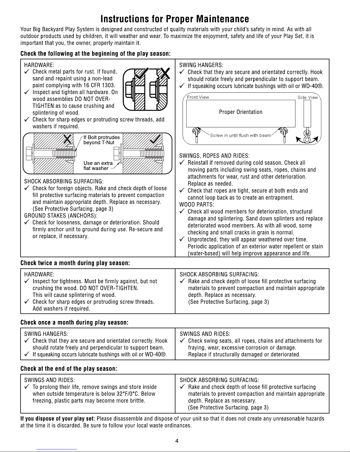
Instructions for Proper Maintenance .......... pg. 4
About Our Wood – Limited Warranty.......... pg. 5
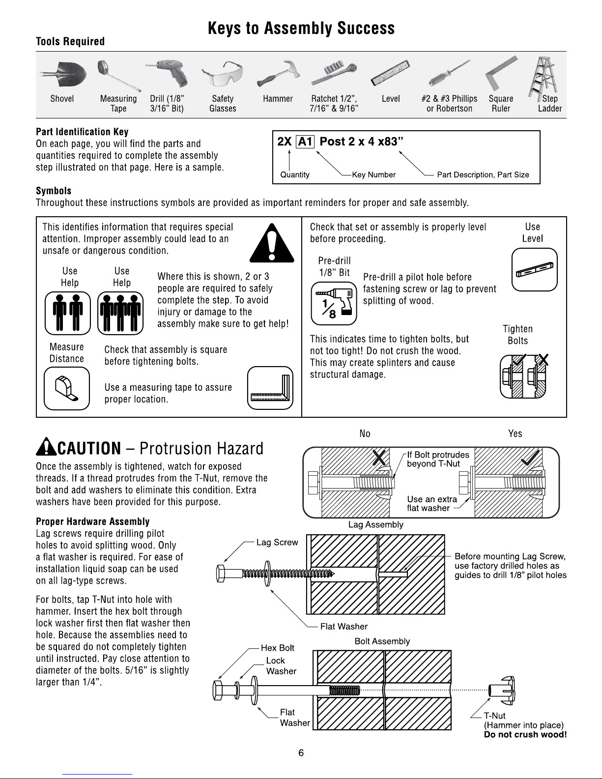
Keys to Assembly Success.................. pg. 6
Part ID .................................. pg. 7
Installation of I.D./Warning Plaque........ Final Step
Solowave Design
375 Sligo Rd. West, PO Box 10
Mount Forest, ON Canada N0G 2L1
Toll Free: 1-877-966-3738
United Kingdom
Toll Free: 0870 145 2145
Email: [email protected]
Other Countries:
Please refer to label affixed to outside of carton.
The 1-877 number on the Owners Manual &
Safety Instructions is for North America only.
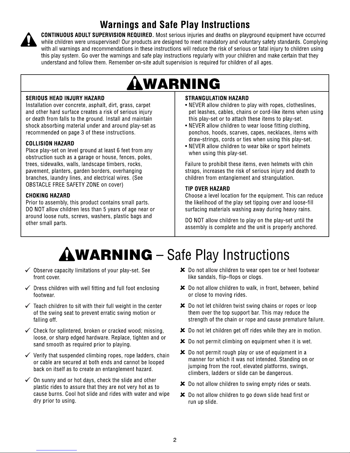
INSTALLATION AND OPERATING INSTRUCTIONS
To reduce the risk of serious injury or death, you must read and
follow these instructions. Keep and refer to these instructions
often and give them to any future owner of this play system. Manufacturer contact information provided below.
OBSTACLE FREE SAFETY ZONE - 5.22 x 7.15 m area requires Protective Surfacing. See page 3.
MAXIMUM VERTICAL FALL HEIGHT - 1.8 m
CAPACITY - 4Users Maximum, Ages 3to 10; Weight Limit 110 lbs. (49.9 kg) per child.
RESIDENTIAL HOME USE ONLY. Not intended for public areas such as schools, churches, nurseries,
day cares or parks
Rev 02/11/2011
3404656E
WARNING
For Outdoor Family Domestic Use Only
ORIANA – A24656E
for use with SELWOOD 1.2 METRE FORT – A23835E


Square
Assembly
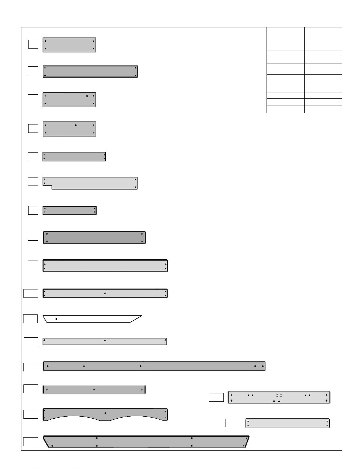
Part Identification (Reduced Part Size) F1 - F18
(22) Wall Board 1/2 x 4 x 20"
F7 3631503 Box 1
1/2" x 4"
1" x 4"
1" x 5"
1" x 6"
5/4" x 6"
5/4" x 5"
5/4" x 4"
2" x 2"
2" x 3"
2" x 4"
2" x 6"
Nominal Size Actual Size
1½" x 5⅜"
1⅜" x 3⅜"
1⅜" x 2½"
1½" x 1½"
1" x 3½"
1" x 4½"
1" x 5½"
⅝" x 5⅜"
⅝" x 4½"
⅝" x 3⅜"
7/16" x 3¼"
3640369 Box 1
F11
(1) Lower Diagonal 2 x 3 x 37"
(8) Cedar Floor Board 1 x 5 x 35¼"
3630621 Box 1
F2
3640791 Box 1
F12
(1) Floor Front 2 x 3 x 46-1/4"
(1) Front Top 1 x 5 x 46-1/2"
3641505 Box 1
F15
(2) CE Access Board 1 x 6 x 19-3/4"
F1 3630606 Box 1
3641554 Box 1
(1) SW Ground 1 x 5 x 77"
F16
3641694 Box 1
F17
(2) End Floor 1 x 5 x 38-1/4"
3641754 Box 1
F18
(1) Lower Back Wall1 x 4 x 31-1/2"
(3) CE Rock Board 1 x 6 x 19-3/4"
3630630 Box 1
F3
(1) SL Ground 1 x 5 x 38-1/4"
3640348 Box 1
F8
3640351 Box 1
(2) Front Back 1 x 5 x 46-5/8"
F9
(2) CE Rock Board 1 x 6 x 19-3/4"
3630631 Box 1
F4
3630705 Box 1
F5
(3) Cedar Wall 1 x 4 x 23½"
3630710 Box 1
(2) Cedar Gap Board 1 x 5 x 35-1/4"
F6
(2) Wall Support 1 x 4 x 38-1/4"
3641502 Box 1
F14
(1) Top Front Back 1 x 4 x 46½"
3640358 Box 1
F10
(4) Post 2 x 4 x 83"
3641500 Box 1
F13

2X 9201100 (2pk)
Corner Brace with
hardware
(1) Roof Support 5/4 x 3 x 33"
OR13
3640403 Box 1
(1) Gusset 5/4 x 4 x 18-1/2"
OR5
(1) Back Divider 1 x 4 x 35-1/4"
OR3
3640360 Box 1
1X 3320185 Rocks (5pk)
Green c/w hardware
(1) Side Joist 2 x 2 x 43"
OR8
3640795 Box 1
(1) Floor Back 5/4 x 4 x 46-3/4" 3640799 Box 1 3641691 Box 1
OR9
3640367 Box 1
(2) Floor Gusset 2 x 3 x 11"
OR4
1X 3799949 (9pk)
Hole Plug
(2) Rock Rail 2 x 3 x 51" 3640349 Box 1
OR1
(3) Ground Stake 1-1/4 x 1-1/2 x 14"
3650318 Box 1
OR15
1X 3750702
Pineview Chalk Wall
Green
1X 9750240
Wellington Canopy Large
Green
(2) Side Roof 1 x 4 x 68" 3641695 Box 1
OR14
3641648 Box 1
OR11
(1) Roof Ridge 5/4 x 3 x 55"
(1) Panel Frame 1 x 2 x 25-1/2"
OR6 3640726 Box 1
3641649 Box 1
OR12
(2) Tarp Front Back 1 x 4 x 55"
(1) Front Divider 1 x 4 x 38"
OR2
3640359 Box 1
Part Identification (Reduced Part Size) OR1 -OR15
(1) Floor Joist 5/4 x 4 x 46-1/2"
3640790 Box 1
OR7
3641646 Box 1
OR10
(1) SW Mount 2 x 4 x 65-3/4"
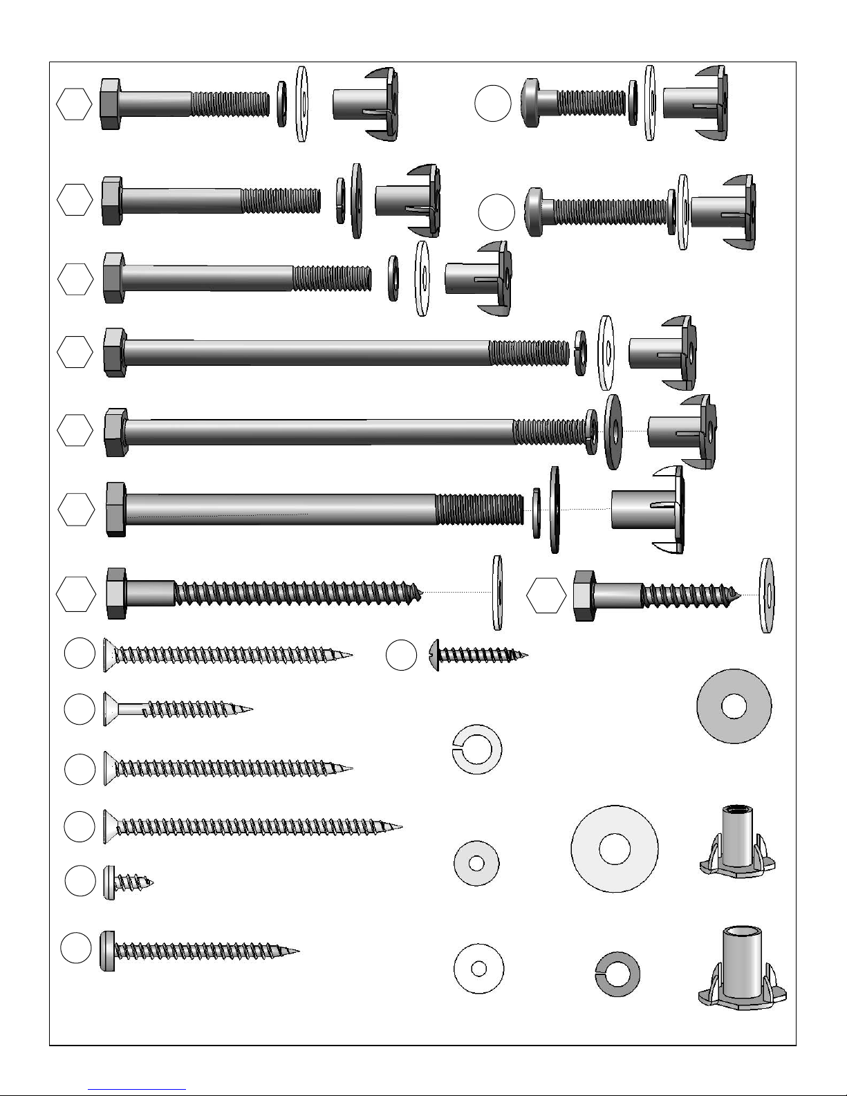
S1 (10) Flat Head Screw #8 x 1 1/8" (9290514)
S7 (17) Pan Screw #12 x 2" (9294620)
S4 (4) Flat Head Screw #8 x 3" (9290530)
S0 (88) Truss Screw
#8 x 7/8" (9229505)
(24)
#8 Flat Washer
(9251500)
S5 (24) Pan Screw #8 x 1/2" (9264504)
S2 (104) Flat Head Screw #8 x 1 1/2" (9260512)
(14)
3/16" Flat Washer
(9251100)
(51)
1/4" Flat Washer
(9251200)
S3 (10) Flat Head Screw #8 x 2 1/2" (9260522)
PB2
(2) Pan Bolt 1/4 x 1 1/4"
1/4" Lock Washer 1/4" Flat Washer 1/4" T-Nut 9274211
PB1
(6) Pan Bolt 1/4 x 3/4"
1/4" Lock Washer 1/4" Flat Washer 1/4" T-Nut 9274203
LS3 9262230
(9) Lag Screw 1/4 x 3" -1/4" Flat Washer LS1 9262212
(4) Lag Screw 1/4 x 1 1/2"
1/4" Flat Washer
H2 (22) Hex Bolt 1/4 x 2" 9277220
1/4" Lock Washer - 1/4" Flat Washer - 1/4" T-Nut
H5 (2) Hex Bolt 1/4 x 4 1/2" 9277242
1/4" Lock Washer - 1/4" Flat Washer - 1/4" T-Nut
G4 (3) Hex Bolt 5/16 x 4" 9277340
5/16" Lock Washer - 5/16" Flat Washer - 5/16" T-Nut
H1
(2) Hex Bolt 1/4 x 1 1/2" 9277212
1/4" Lock Washer - 1/4" Flat Washer - 1/4" T-Nut
H3 (2) Hex Bolt 1/4 x 2 1/2" 9277222
1/4" Lock Washer - 1/4" Flat Washer - 1/4" T-Nut
Hardware Identification (Actual Size)
H6 (2) Hex Bolt 1/4 x 4 3/4 9277243
1/4" Lock Washer - 1/4" Flat Washer - 1/4" T-Nut
(3)
5/16" Lock Washer
(9253300)
(38) 1/4" T-Nut
(9285200)
(3) 5/16" T-Nut
(9285300)
(3)
5/16" Flat Washer
(9251300)
(38)
1/4" Lock Washer
(9253200)

PRODUCT NUMBER: A23835E & A24656E
CARTON I.D. STAMP: __ __ __ __ __ 14459 ___ (Box 1)
CARTON I.D. STAMP: __ __ __ __ __ 14459 ___ (Box 2)
CARTON I.D. STAMP: __ __ __ __ __ 14459 ___ (Box 3)
CARTON I.D. STAMP: __ __ __ __ __ 14459 ___ (Box 4)
CARTON I.D. STAMP: __ __ __ __ __ 14459 ___ (Box 5)
CARTON I.D. STAMP: __ __ __ __ __ 14459 ___ (Box 6)
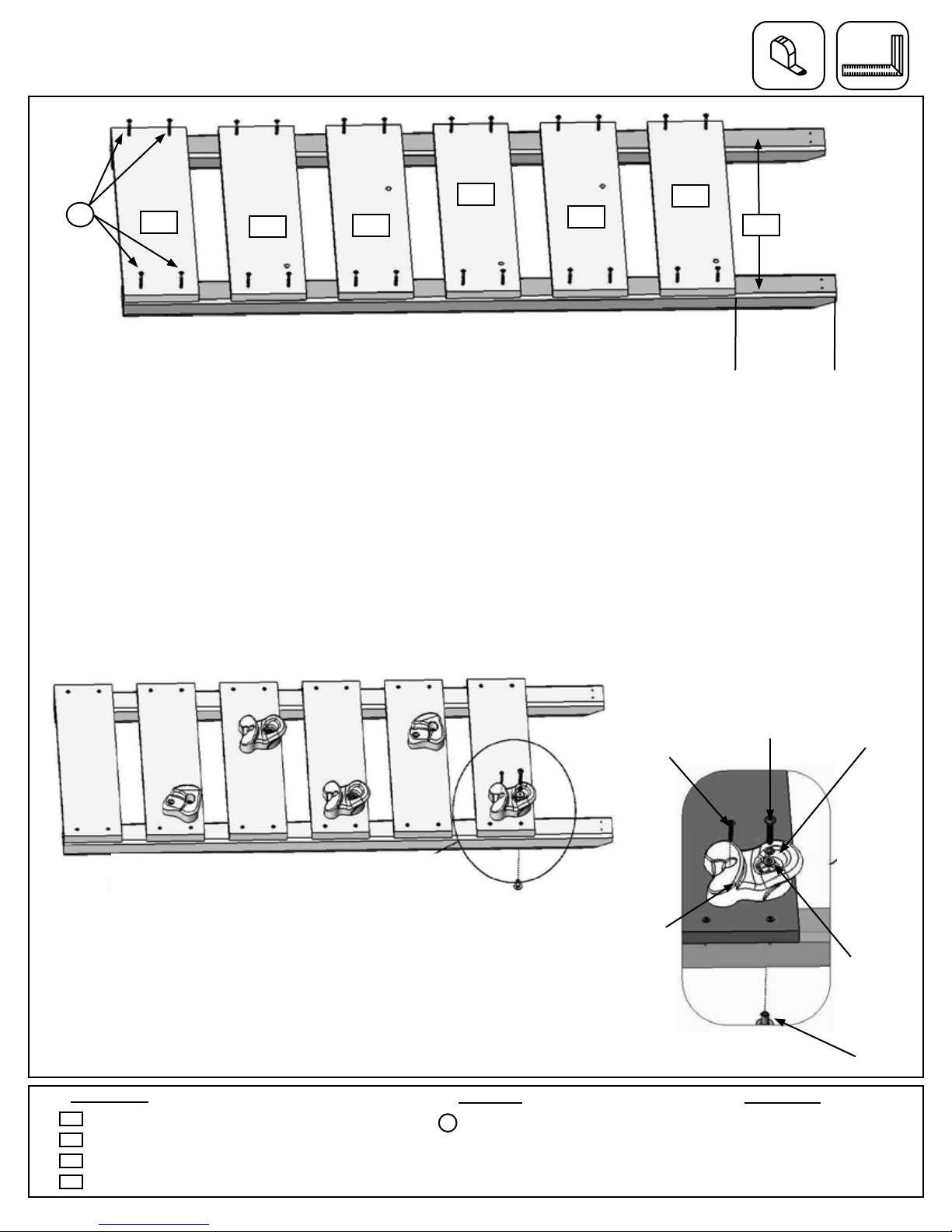
Step 1: Rock Wall Assembly
F1 F4
F3
F3 F3
F4 OR1
Fig. 1.1
Pan Screw Pan Bolt
Flat
Washer
Rock
Barrel Nut
Lock
Washer
Fig. 1.3
Fig. 1.2
Note: Gaps between boards 2-1/8”,
not to exceed 2-3/8”
Note: The holes
in the rock boards
must orient to the
top of the boards.
x 4 per
board
Bottom
8-1/8”
approx.
1 x CE Access Board 1 x 6 x 19-3/4”
3 x CE Rock Board 1 x 6 x 19-3/4”
2 x CE Rock Board 1 x 6 x 19-3/4”
2 x Rock Rail 2 x 3 x 51”
F1
F4
F3
OR1
24 x #8 x 1-1/2” Wood Screw
S2 5 x Rocks (with hardware)
Hardware Other Parts
Wood Parts
A: Lay 2 (OR1) Rock Rails down, side by side with angled edges facing down. (g. 1.1)
B: Place (F1) CE Access Board on the bottom of each (OR1) Rock Rail as shown in g. 1.1. Make sure (F1) CE
Access Board is square and ush to the outside and bottom edges of each (OR1). Attach using 4 (S2) #8 x 1-1/2”
Wood Screws.
C: 8-1/8” down from the top of both (OR1) Rock Rails place 1 (F3) CE Rock Board, making sure the sides are
ush to the outside edges of each (OR1) Rock Rail. Attach using 4 (S2) #8 x 1-1/2” Wood Screws. (g. 1.1)
D: In between the (F1) CE Access Board and (F3) CE Rock Board stagger 2 (F4) and 2 (F3) CE Rock Boards
using 4 (S2) #8 x 1-1/2” Wood Screws per board. Placing them as shown in (g. 1.1), this will prevent rocks from
forming a straight line. Make sure the gap between boards are spaced 2-1/8” and does not exceed 2-3/8”.
E: Place 1 rock on each (F3) and (F4) CE Rock
Board (g. 1.2) and attach using included hardware.
The screw must be in the hole directly under the Pan
Bolt, it will stop the rock from spinning. (g. 1.3)
S2
11
Note: Pre-drill all holes using a 1/8” drill
bit before installing the lag screws.
Hex Bolt Assembly
Lock
Washer T- Nut
Flat
Washer
He x
Bolt
Predrill Pilot Holes for Lag Screw
Lag
Screw
Flat
Washer
Predrill 1/8”
pilot hole
Use factory drilled
hole as a guide
Fig. 2.1
F17
F13
F8
Notice hole
positioning
F13
H2
H2
H2
H2
F17
Fig. 2.2
1x End Floor 1 x 5 x 38-1/4”
1x SL Ground 1 x 5 x 38-1/4”
2x Post 2 x 4 x 83”
F17
F13
F8
6 x 1/4 x 2” Hex Bolt
(1/4” lock washer, 1/4” at washer, 1/4” t-nut)
2 x 1/4 x 1-1/2” Lag Screw
(1/4” at washer)
Hardware
Wood Parts
H2
LS1
F13
A: To 2 (F13) Posts attach 1 (F8) SL Ground with 4 (H2) 1/4 x 2” Hex Bolts (with lock washer, at washer and
t-nut) and in 1 (F17) End Floor in the bottom holes with 2 (H2) 1/4 x 2” Hex Bolts (with lock washer, at washer
and t-nut). (g. 2.1)
B: Make sure assembly is square and then in the top holes of the (F17) End Floor fasten to (F13) Posts using 2
(LS1) 1/4 x 1-1/2” Lag Screws (with at washer). (g. 2.2)
C: Tighten all bolts.
LS1
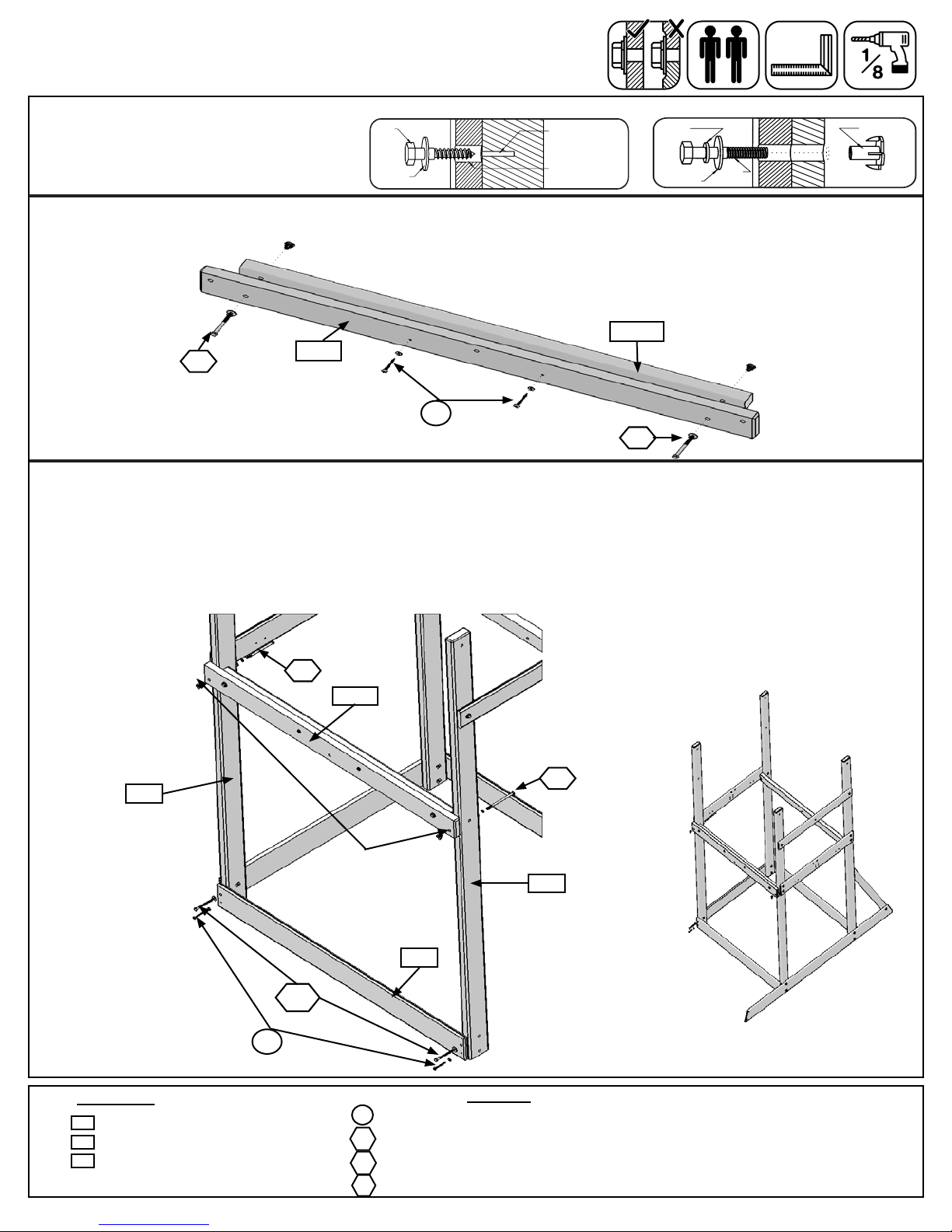
Step 2: Wall Assembly
If you purchased a Selwood Monkey Ladder or Selwood Spiral
Wave Slide refer to that manual.
12

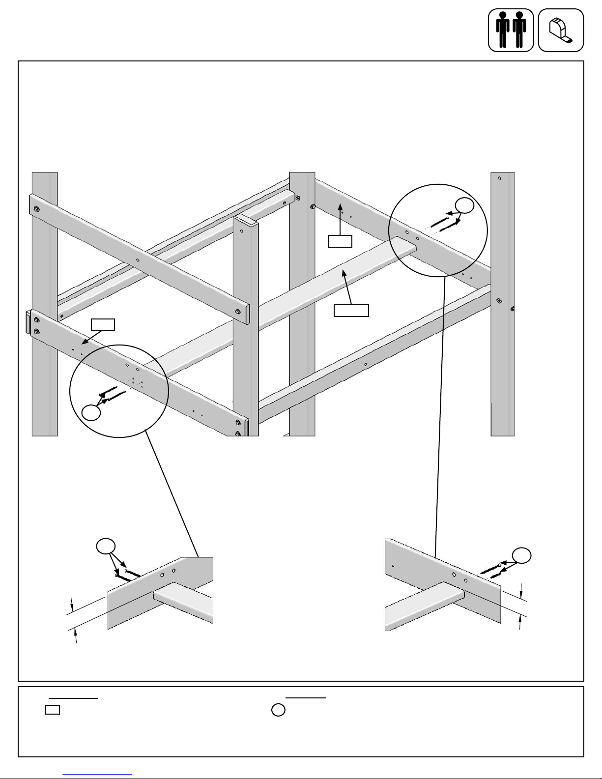
Step 3: Swing Wall Assembly
Note: Pre-drill all holes using a 1/8” drill
bit before installing the lag screws.
Hex Bolt Assembly
Lock
Washer T- Nut
Flat
Washer
He x
Bolt
Predrill Pilot Holes for Lag Screw
Lag
Screw
Flat
Washer
Predrill 1/8”
pilot hole
Use factory drilled
hole as a guide
Fig. 3.1 F17
F13
F16
Notice hole
positioning
F14
Fig. 3.2
F13
H2
H2 H2
H2
F16
H2
F11
LS3
1 x End Floor 1 x 5 x 38-1/4”
1 x SW Ground 1 x 5 x 77”
1 x Lower Diagonal 2 x 3 x 37”
2 x Post 2 x 4 x 83”
1 x Wall Support 1 x 4 x 38-1/4”
F17
F16
F11
F13
F14
Hardware
Wood Parts
9 x 1/4 x 2” Hex Bolt
(1/4” lock washer, 1/4” at washer, 1/4” t-nut)
1 x 1/4 x 3” Lag Screw
(1/4” at washer)
2 x 1/4 x 1-1/2” Lag Screw
(1/4” at washer)
H2
LS3
LS1
F13
LS1
B: Make sure assembly is square and then fasten (F17) End Floor to (F13) Posts in the top holes using 2 (LS1)
1/4 x 1-1/2” Lag Screws (with at washer). (g. 3.2)
C: Attach (F11) Lower Diagonal to (F16) SW Ground with 1 (H2) 1/4 x 2” Hex Bolt (with lock washer, at washer
and t-nut) and to (F13) Post using 1 (LS3) 1/4 x 3” Lag Screw (with at washer). (g. 3.2)
D: Tighten all bolts.
A: To 2 (F13) Posts attach 1 (F16) SW Ground with 4 (H2) 1/4 x 2” Hex Bolts (with lock washer, at washer and
t-nut); 1 (F17) End Floor in the bottom holes and 1 (F14) Wall Support with 2 (H2) 1/4 x 2” Hex Bolts (with lock
washer, at washer and t-nut) in each board. (g. 3.1)
13

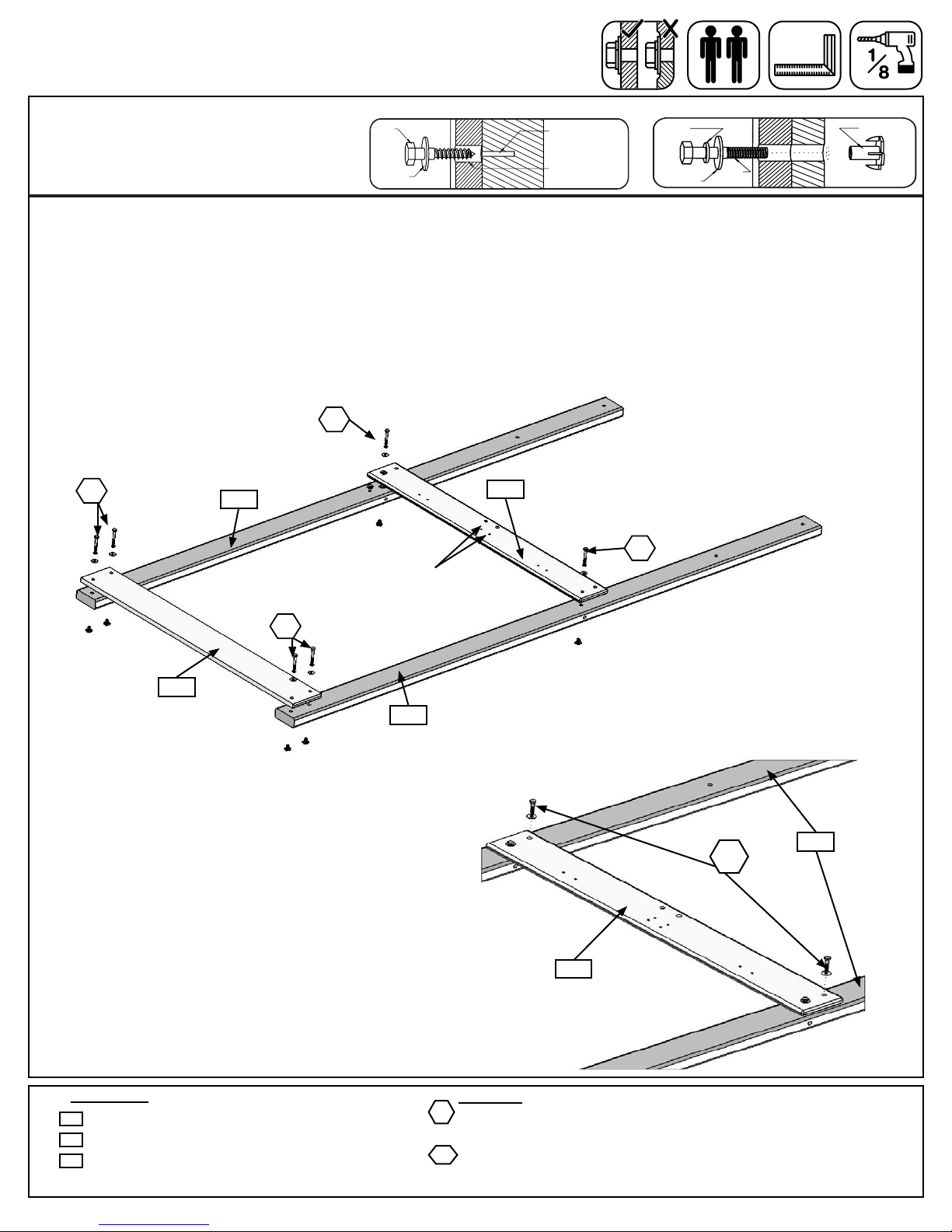
Step 4: Front Frame Assembly
Note: Pre-drill all holes using a 1/8” drill
bit before installing the lag screws.
Hex Bolt Assembly
Lock
Washer T- Nut
Flat
Washer
He x
Bolt
Predrill Pilot Holes for Lag Screw
Lag
Screw
Flat
Washer
Predrill 1/8”
pilot hole
Use factory drilled
hole as a guide
Fig. 4.1
Notice hole
location towards
bottom
F12
LS3
H6
F9
S7
S7 LS3
H6
1 x Front Back 1 x 5 x 46-5/8”
1 x Floor Front 2 x 3 x 46-1/4”
F9
F12
Hardware
Wood Parts
2 x 1/4 x 4-3/4” Hex Bolt
(1/4” lock washer, 1/4” at washer, 1/4” t-nut)
2 x 1/4 x 3” Lag Screw
(1/4” at washer)
2 x #12 x 2” Pan Screw (with 3/16” at washer)
H6
LS3
S7
F13
F13
A: Attach (F12) Floor Front to both (F13) Posts using 2 (H6) 1/4 x 4-3/4” Hex Bolts (with lock washer, at washer
and t-nut). (g. 4.1)
B: Square and attach 1 (F9) Front Back to the bottom of (F13) Posts with 2 (LS3) 1/4 x 3” Lag Screws (with at
washer) in the top (pre-drilled) hole and 2 (S7) #12 x 2” Pan Screws (with 3/16” at washer) in the bottom holes
as shown in (g. 4.1).
C: Tighten all bolts.
Note: Some
boards removed
for clarity
14
Step 5: Back Frame Assembly
Note: Pre-drill all holes using a 1/8” drill
bit before installing the lag screws.
Hex Bolt Assembly
Lock
Washer T- Nut
Flat
Washer
He x
Bolt
Predrill Pilot Holes for Lag Screw
Lag
Screw
Flat
Washer
Predrill 1/8”
pilot hole
Use factory drilled
hole as a guide
Fig. 5.1
OR8
F9
S7
H3
Fig. 5.2
OR9
Fig. 5.3
H3
S7
H5
H5
LS3
1 x Front Back 1 x 5 x 46-5/8”
1 x Side Joist 2 x 2 x 43”
1 x Floor Back 5/4 x 4 x 46-3/4”
F9
OR8
Hardware
Wood Parts
4 x #12 x 2” Pan Screw (with 3/16” at washer)
2 x 1/4 x 4-1/2” Hex Bolt (1/4” lock washer, 1/4” at washer, 1/4” t-nut)
2 x 1/4 x 2-1/2” Hex Bolt (1/4” lock washer, 1/4” at washer, 1/4” t-nut)
2 x 1/4 x 3” Lag Screw (1/4” at washer)
H5
LS3
S7
OR9
Notice hole
location towards
bottom
H3
A: Attach (OR9) Floor Back to (OR8) Side Joist with 2 (H3) 1/4 x 2-1/2 Hex Bolts (with at washer, lock washer
and t-nut) and 2 (S7) 12 x 2” Pan Screws (with at washers) as shown in g. 5.1.
B: Attach Floor Back Assembly from Step A to both (F13) Posts with 2 (H5) 1/4 x 4-1/2” Hex Bolts (with lock
washer, at washer and t-nut) through (OR9) Floor Back. Notice the hole orientation towards bottom of board.
(g. 5.2 & 5.3)
C: Square and attach (F9) Front Back ush to the bottom and outside edge of (F13) Posts with 2 (LS3) 1/4 x 3”
Lag Screws (with at washer) in the top, pre-drilled holes and 2 (S7) 12 x 2” Pan Screws (with 3/16” at washer)
in the bottom holes as shown in g. 5.2 & 5.3.
D: Tighten all bolts.
Note: Some
boards removed
for clarity
15
OR9
F13
F13
2-1/8"
2-1/8"
2-1/8"
2-1/8"
2-1/8"
2-1/8"
Fig. 6.1
OR7
Fig. 6.2
Fig. 6.3
S4
S4
S4
1 x Floor Joist 5/4 x 4 x 46-1/2”
Hardware
Wood Parts
4 x #8x 3” Wood Screw
S4
OR7
F17
F17
S4
A: From inside of assembly, measure 2-1/8” down from the tops of each (F17) End Floor (g. 6.2 & 6.3) then
attach (OR7) Floor Joist using 2 (S4) #8 x 3” Wood Screws per end. (g. 6.1)
Step 6: Floor Frame Assembly
If you purchased a Selwood Monkey Ladder or Selwood Spiral Wave Slide
refer to that manual.
16
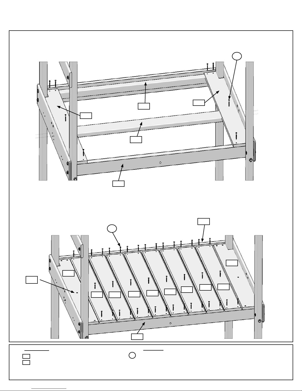
Step 7: Attach Floor Boards
Fig. 7.1
Fig. 7.2
S2
F2
F6
F6
F2
F2
F2
F2
F2
F2
F2
x 5 per board
x 5 per board
8 x Cedar Floor Board 1 x 5 x 35-1/4”
2 x Cedar Gap Board 1 x 5 x 35-1/4”
F2
F6
Hardware
Wood Parts
50 x #8 x 1-1/2” Wood Screw
S2
F12
OR8
OR7
F6
F6
OR7
Under oor boards
F12
OR8
S2 Under oor boards
A: Install 1 (F6) Cedar Gap Board tight to each end of the assembly attaching to (OR8) Side Joist, (OR7) Floor
Joist and (F12) Front Floor using 5 (S2) #8 x 1-1/2” Wood Screws per board. (g. 7.1)
B: In between both (F6) Cedar Gap Boards place 8 (F2) Cedar Floor Boards making sure all boards are evenly
spaced. Attach to (OR8) Side Joist, (OR7) Floor Joist and (F12) Front Floor using 5 (S2) #8 x 1-1/2” Wood
Screws per board. (g. 7.2)
17

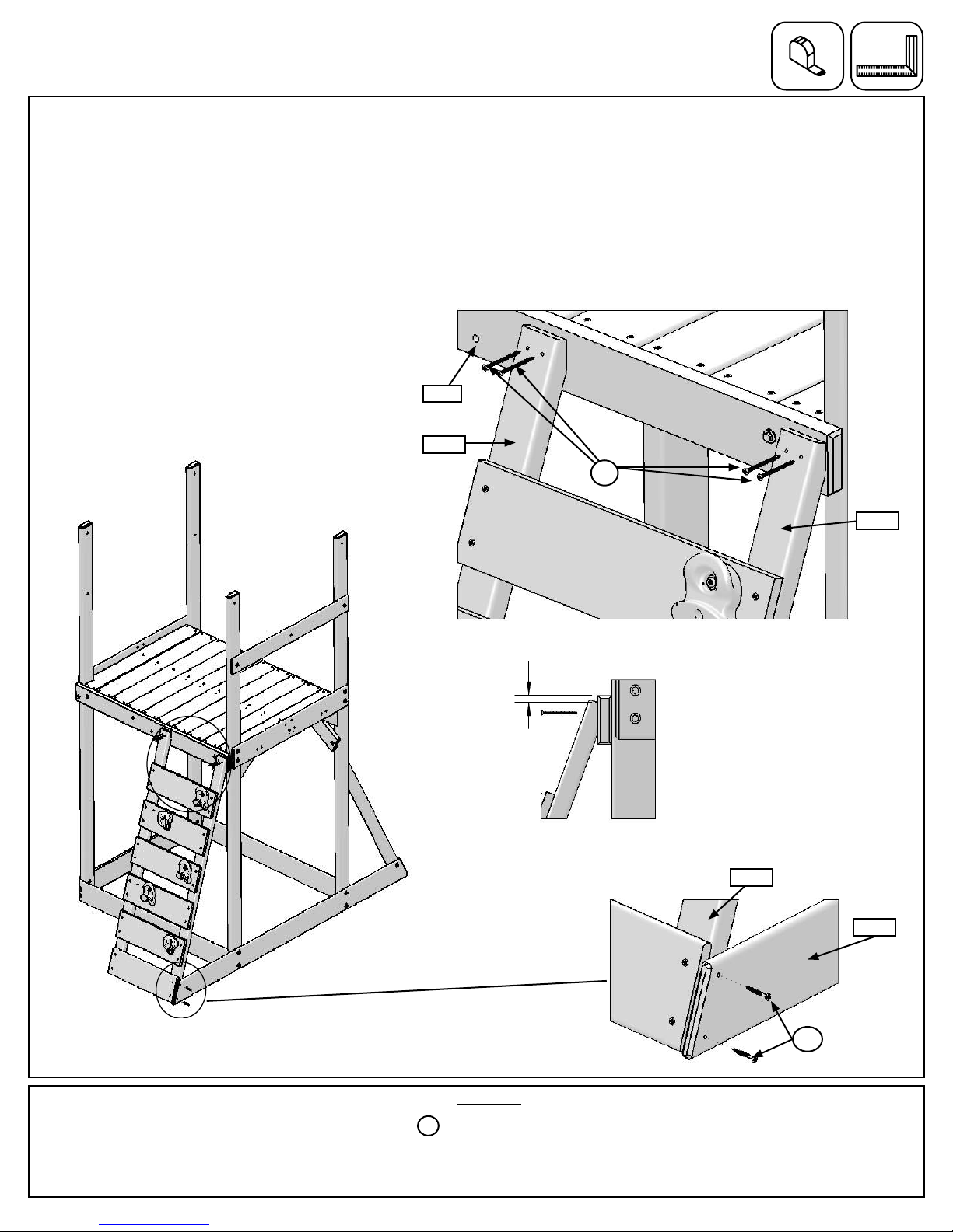
Step 8: Attach Gussets
4 x #8 x 1-1/2” Wood Screw
4 x 1/4 x 3” Lag Screw
(1/4” at washer)
1 x Gusset 5/4 x 4 x 18-1/2”
2 x Floor Gusset 2 x 3 x 11”
Fig. 8.2
OR4
Fig. 8.3
Fig. 8.4
OR5
LS3
OR4
LS3LS3
Note: Pre-drill all holes using a 1/8” drill
bit before installing the lag screws.
Predrill Pilot Holes for Lag Screw
Lag
Screw
Flat
Washer
Predrill 1/8”
pilot hole
Use factory drilled
hole as a guide
Fig. 8.1
S2
OR5
OR4
LS3
S2
Hardware
Wood Parts
F13
OR4
F13
F17
F12
Under fort view
F6
1”
A: On the Swing Wall side place 1 (OR4) Floor Gusset tight to the bottom of the (F6) Cedar Gap Board make sure
assembly is square, then attach to each (F13) Post with 1 (LS3) 1/4 x 3” Lag Screw (with at washer) per gusset in
the pre-drilled holes as shown in g. 8.1, 8.2 and 8.3.
B: Attach each (OR4) Floor Gusset to (F17) End Floor using 2 (S2) #8 x 1-1/2” Wood Screws per gusset. (g.
8.2)
C: Place 1 (OR5) Gusset tight to the bottom of (F12) Floor Front so there is a 1” overhang from the outside edge
of (F13) Post. (g. 8.1 & 8.4)
D: Attach (OR5) Gusset to (F13) Post with 1 (LS3) 1/4 x 3” Lag Screw (with at washer) from inside the assembly
and then to (F12) Floor Front with 1 (LS3) 1/4 x 3” Lag Screw (with at washer) as shown in g. 8.4.
18
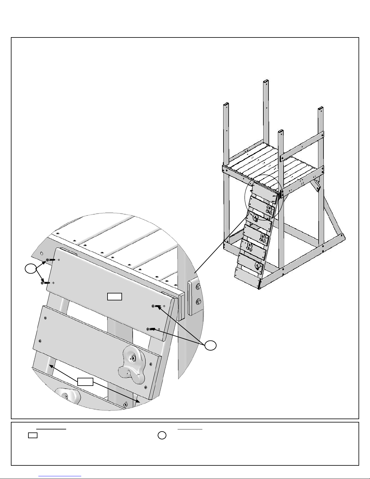
Step 9: Attach Rock Wall to Fort
1/2"
1/2"
1/2"
1/2"
Fig. 9.1
S2
Fig. 9.3
Fig. 9.4
Fig. 9.2
6 x #8 x 1-1/2” Wood Screw
S2
Hardware
OR1
OR9
F16
S2
A: Place Rock Wall Assembly from Step 1 on (OR9) Floor Back, ush to the edge and 1/2” down from the top as
shown in 9.1, 9.2 & 9.3. Attach (OR1) Rock Rails to (OR9) Floor Back using 4 (S2) #8 x 1-1/2” Wood Screws as
shown in g. 9.2 & 9.3.
B: Make sure the assembly is square then attach (F16) SW Ground to (OR1) Rock Rail using 2 (S2) #8 x 1-1/2”
Wood Screws. (g. 9.4)
OR1
OR1
19
F1
S2
Fig. 9.5
4 x #8 x 1-1/2” Wood Screw
1 x CE Access Board 1 x 6 x 19-3/4”
F1 S2
Hardware
Wood Parts
S2
OR1
Step 9: Attach Rock Wall to Fort cont.
C: Attach (F1) CE Access Board to top of Rock Wall Assembly, ush to top of (OR1) Rock Rails using 4 (S2) #8 x
1-1/2” Wood Screws. (g. 9.5)
20
Table of contents
Popular Game manuals by other brands


Infinite dreams
Infinite dreams K-Rally Game brochure

KICK
KICK Arcadia Brown Assembly instructions

Jolly Roger
Jolly Roger INTERNATIONAL SPEEDWAY CAR CAROUSEL Handbook

ESCALADE
ESCALADE Triumph 35-7077 instruction manual

Nintendo
Nintendo Mario Kart Live Home Circuit manual

TAG
TAG Wrestling DVD Board Game instructions


