4
2. SPIKE SYSTEM AND NODE GUIDE
2.1 SPIKE SYSTEM OVERVIEW
The SPIKE Pinball system is a rugged, distributed, and
embeddedplatformcustom-designedfortherigorsofthepinball
machineenvironment.SPIKEtakesadvantageofmodern
technologies to deliver an immersive pinball experience that
supportsmodernfeatures,reducescabling,andincreases
serviceability and reliability.
A Stern Pinball machine based on the SPIKE system will have at
least one node networked together with the SPIKE node bus. The
primaryCPUisnetworkedtooneormoreinput/outputnodes
overstandardCategory5UTP(unshieldedtwistedpair)ethernet
cabling.
Therearevetypesofnodes.
• CPUnode(Node0)-Theprimarynodethatcontrolsother
nodesinthesystem.Containsthegamesoftwareforthe
systemandprovidesSPIKEnodebuspowerforothernodes.
• Cabinetnode(Node1)-Specializednodewithspecic
inputsandoutputsforcoindoors,tiltmechanisms,andother
cabinet devices.
• 48Vplayeldnode-Controlshighpowerdevicessuchas
coilsandashers,andalsosupportsafewswitchandlow-
power outputs.
• Lightandswitchnode(32Switch+LEDNode)-Switchand
low-power LED outputs. Contains as many 32 switch inputs
and light outputs.
• Node extensions - These LED boards add additional low-
powerinputandoutputstoaspecicPowerorI/Onodeand
are connected with simple serial bus.
2.2 NODE BUS CABLING
TheSPIKEnodebusutilizesstandardEthernet-styleRJ45
8-pin modular jacks and ethernet cabling. SPIKE nodes are not
compatible with standard computer networking equipment.
CAUTION: Plugging a SPIKE Node or CPU board into a standard
Ethernet port may damage one or both devices and void your
warranty.
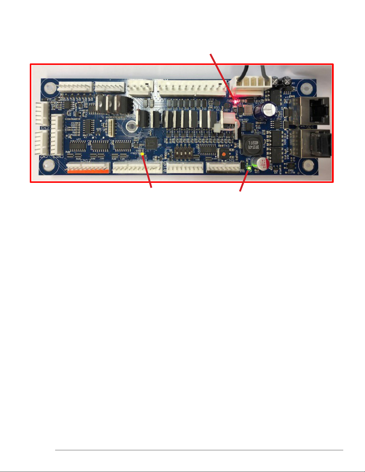
2.3 SYSTEM POWER
TheSPIKESystemispoweredfroman48VDCswitchingpower
supply. Each SPIKE node converts this voltage to lower voltages
requiredbythenodeanditsspeciccomponents.ASPIKEnode
controls high-power outputs such as game coils and some LEDs.
These nodes are supplied directly with 48V system power. Other
nodes are low-power boards that read switch inputs and output
to standard-brightness LEDs.
2.4 SPIKE NODE ADDRESSES
EachSPIKEnodehasauniqueaddressrangingfrom0to15.Not
alladdressesareusedinallgames.Nodescanbeofthesame
partnumber,sotheaddressisspeciedontheDIPswitcheson
each node. When replacing a node, be certain that the correct
address is set. Nodes can have 3-position or 4-position DIP
switches.Refertotheappropriatetabletosettheaddressfor
eachtypeofNode.Thecorrectaddressforanodecanbefound
intheSPIKEnodereferencesectionofthemanualorinthegame
diagnosticsoftware.Address0isreservedfortheCPUnode,
wherethegamesoftwareresides.Address1isreservedforthe
cabinet node. These two nodes do not have DIP switches as
theiraddressisnotcongurable.
SPIKEnodeaddressesfornodeswith3-positionDIPswitches.
Addresses 0-7 are not used by SPIKE nodes with 3-position DIP
switches.
Address 1 2 3
8 OFF OFF OFF
9 OFF OFF ON
10 OFF ON OFF
11 OFF ON ON
12 ON OFF OFF
13 ON OFF ON
14 ON ON OFF
15 ON ON ON
SPIKEnodeaddressesfornodeswith4-positionDIPswitches.
Addresses0-7arereservedforxed-functionnodesanddonot
requireconguration.
Address 1 2 3 4
8 OFF OFF OFF OFF
9 OFF OFF ON OFF
10 OFF ON OFF OFF
11 OFF ON ON OFF
12 ON OFF OFF OFF
13 ON OFF ON OFF
14 ON ON OFF OFF
15 ON ON ON OFF