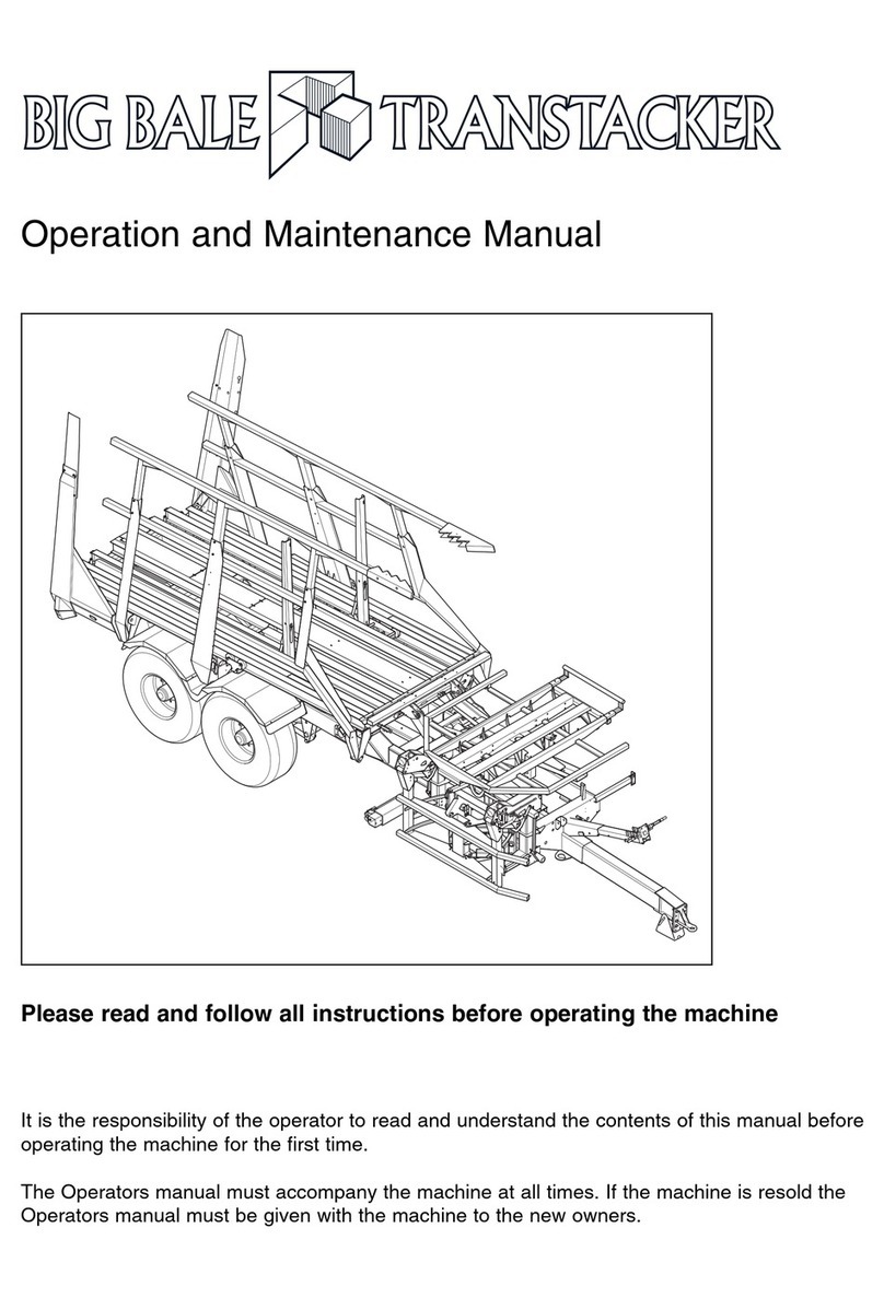
BIG BALE Transtacker 4100 User manual

Operation and Maintenance
Manual Transtacker 4100
Please read and follow all instructions before operating the machine
It is the responsibility of the operator to read and understand the contents of this manual
before operating the machine for the first time.
The Operators manual must accompany the machine at all times. If the machine is resold
the Operators manual must be given with the machine to the new owners.

Contents
Page
Title
1.0 Introduction …………………………………………………………………………….. 1
Description ……………………………………………………….... 1
……………………………………. 1
……………………………….. 1
………………………………. 1
………………………………. 2
……………………………………………….. 2
1.1
1.2
1.3
1.4
1.5
1.6
1.7
SAFETY ALERT SYSMBOLS
Machine Identification Plate
Intended Use of the Machine
Construction and Use Act UK
Noise Declaration
Accessories and Attachments ……………………………… 2
2.0 …………………………………………………………………………….. 2
3.0 …………………………………………………………………… 3
4.0
Specification
Machine Overview
Safety ………………………………………………………………………………………. 4
4.1 Safety in Operation & Maintenance ……………………. 4
5.0 Operation ………………………………………………………………………………….6
5.1 Attachment to the Tractor ………………………………….. 6
5.2 Hydraulics …………………………………………………………… 6
5.3 PTO (Power Take-Off) …………………………………………. 6
5.4 Electrical ……………………………………………………………… 7
5.5 Joystick Functions ……………………………………………….. 8
5.6 Screen Functions ………………………………………………… 9
5.7 Auto Function ……………………………………………………… 10
5.8 …………………………………. 12
5.9
Erecting a Complete Tower
Placing Towers Against Existing Towers ………………. 13
5.10 Erecting a Part Load Tower …………………………………. 14
5.11 Re-Picking a Complete Tower ……………………………… 15
5.12 Getting started Manually ……………………………………. 17
5.13 Pickup Manual With Grab Arm ……………………………. 17
5.14 Stacking (Automatic) …………………………………………… 19
5.15 Stacking Without Tie (Manual) ……………………………. 20
5.16 Stacking Tie (Manual) …………………………………………. 21
5.17 Finishing a Stack …………………………………………………. 23
5.18 Operation as a Bale Transporter …………………………. 23
6.0 Adjustments ……………………………………………………………………………. 24
6.1 ……….…………………………………………….. 24
6.2 ………………………………………. 25
6.3
Pickup Height
Fork Cable Adjustments
Turntable Bale Stop …………………………………………….. 25
6.4 ….………………………………………………….. 26
6.5 ………………………………………………………… 26
6.6
900mm Stop
Pickup Tines
Pickup Shoe …………………………………………………………. 26
6.7 ………………………………………….. 27
6.8
Grab Arm CTF Paddle
Proximity Sensors ……………………………………………….. 27
Turntable - Middle ……………………………………. 28
……………………………….…… 28
………………..………………….. 29
6.8.1
6.8.2
6.8.3
6.8.4
Turntable – Extend
Gates Open LH/RH
Tip Bed Up Partial ……………………………………... 29
6.9 Rotary Sensors ……………………………………………………. 30
6.10 Adjustable Stop on Grab Arm and Turntable Rotate …… 31
6.11 Pressurizing the Bump Paddle …………………………..… 32
6.12 Guide Bar Wear Pads ……………………………………….…. 32
6.13 Pulley Beam Trolley Wear Pads …………………………… 33
6.14 Fork Trolley Stops ……………………………………………….. 33
6.15 Removal of Side Gate Safety Pins ……………………….. 33
7.0 Diagnostics / Settings ………………………………………………………………. 34
……………… 34
……………….. 34
…………………… 34
……… 35
…………………. 35
7.1
7.2
7.3
7.4
7.5
7.6
Diagnostics Page 1 – Proximity Sensors
Diagnostics Page 2 – Pressure Sensors
Diagnostics Page 3 – Rotary Sensors
Setting Page 1 – Rotary Transducers Address
Setting Page 2 – Valve Demand Rates
Setting Page 3 – Demand/Angle Curves ………………. 35

Contents
Page
Title
Setting Page 4 – Pressure Transducer Address …… 35
Setting Page 5 – Settings …………………………….………. 35
7.7
7.8
7.9 Bale Counter ……………………………………………………….. 36
8.0 Trouble Shooting ……………………………………………………………………… 37
…………………………………… 37
…………………………………………………………………. 37
………………………………………………………………. 37
………………………………………… 38
…………………………………………………. 38
………………………………….. 39
……………………………………. 39
………………………………… 40
8.1
8.2
8.3
8.4
8.5
8.6
8.7
8.8
8.9
Connecting to the Tractor
Pickup
Stacking
Initial Troubleshooting
Sensor Error Log
Hydraulic Troubleshooting
CAN Bus Troubleshooting
Auto Open Troubleshooting
Auto Pickup Troubleshooting ……………………………… 42
8.10 Auto Stack Troubleshooting ………………………………...44
8.11 Auto Tip Bed Down Troubleshooting …………………… 46
8.12 Auto Tip Bed Up Troubleshooting ……………………….. 47
9.0 Tips and Information ………………………………………………………………… 48
……………………………………….….. 48
……………………………………………….. 48
……………………………………………...... 49
9.1
9.2
9.3
9.4
Side by Side Stacking
Stacking Off Stack
Extra Pickup Bale
Adding Layer Count …………………………………………….. 49
10.0 Electrical System ………………………………………………………………………. 50
10.1 Electrical System Structure …………………………………. 50
10.1.1 CAN Bus Structure …………………………………….. 51
10.1.2 Lighting Wiring ………………………………………….. 52
10.1.3 Transtacker Wiring Loom Layout ………………. 54
10.2 Sensor Functions ………………………………………………… 55
11.0 Hydraulic System ……………………………………………………………………… 55
11.1 Hydraulic Standby Pressure (Loading Sensing) ……. 56
11.2 General Hydraulic Information ……………………………. 56
11.3 Valve Block Details ……………………………………………… 57
11.4 Valve Block Schematic ………………………………………… 60
12.0 Electrical & Hydraulic Systems ………………………………………………….. 61
12.1 Chassis Sensor Locations …………………………………….. 61
12.2 Platform Sensor Locations …………………………………. 62
13.0 Maintenance ……………………………………………………………………………. 63
13.1 Service Schedule …………………………………………………. 63
13.2 Pickup Grease Points ………………………………………….. 64
13.3 Grab Arm Grease Points ……………………………………… 65
13.4 Turntable/A-Frame Grease Points ………………………. 66
13.5 Side Gate Grease Points ……………………………………… 67
13.6 Rear Clamps Grease Points …………………………………. 68
13.7 Chassis Grease Points …………………………………………. 69
13.8 Platform Grease Points ……………………………………….. 70
13.9 Axle Grease Points ………………………………………………. 71
13.10 Storage ……………………………………………………………….. 72
13.11 Dismantling and Disposal ……………………………………. 72
………………………………………………………………………………….. 72
………………………………………………………………………………. 73
14.0 Warranty
15.0 Error Codes
16.0 Operator Notes ………………………………………………………………………… 81

1.0 Introduction
1.1 Description
In choosing the Big Bale Transtacker 4100 you have
purchased a machine of exceptional versatility.
This manual should be regarded as essential reading in the
interest of safety, efficiency and longevity of the machine.
References to Right and Left in this manual are taken as
viewing the machine from the rear facing in the normal
direction of travel.
1.3 Machine Identification Plate
If service parts are required it is necessary to quote the
machine serial number. This is located at the front right
hand side of the machine on top of the drawbar front
plate. It is recommended that this information be
transferred to this page on delivery of the Transtacker
4100.
Model ________________________
Serial No. ________________________
Year of Manufacture ________________________
Date of Delivery ________________________
Unladen Weight ________________________
Max Gross Weight ________________________
Max Drawbar Load ________________________
1.2 SAFETY ALERT SYMBOLS
This warning symbol appears throughout this hand book.
Attention is drawn to items or operations that could cause
danger to the operator or to persons nearby.Please read
safety messages carefully and have a full understanding of
their importance.
Always abide by the requirements.
WARNING: Warnings call attention to instructions, which
need to be followed precisely to avoid a hazardous
situation.
CAUTION: Cautions call attention to instructions, which
must be followed precisely to avoid damaging the product,
process or surroundings.
Fig. 1
1.4 Intended Use of the Machine
The Big Bale Transtacker is designed to assemble
various sized big bales, 2.4m (8') long, into completed
stacks and erect them into a tower.
The various sizes of bales must have a width or depth
which can, (when arranged side by side in some multiple),
form a rectangle that is 2.4m(8') square. Bale length is
permitted to vary considerably but to tie layers, 2.4m(8") ±
0.1 is preferred.
The machine will also recover previously erected towers
and re-erect them in a new location.
The bales can be of various straws and hays generally
found in agricultural use.
The machine is generally towed with an agricultural
tractor recommended minimum of 6 Tonnes,150 HP.
1

1.0 Introduction
1.7 Accessories and Attachments
High Speed Axles
Above 30 kph (20 mph), A.B.S. with air brakes may be
required. Air Brakes and A.B.S comes standard with the
Transtacker 4100 but needs installing into the tractor if it is
not already standard on the tractor.
It is important to note that high-speed use on highways
may be restricted by a machine width in excess of 2.55 m.
Flashing Beacon
A flashing beacon is mounted on the panel adjacent to the
number plate. These flashing beacon is attached to your
tractor side lights when the lights are fitting. When paired
in conjunction with a tractor cab top mounted unit, it
provides all round visible flashing lights (Fig. 2).
Hydraulic Sprung Drawbar
The drawbar suspension consists of 2 hydraulic cylinders
that are dampened for a more superior ride and control to
the Transtacker and Tractor. The height of the drawbar can
be adjusted by one of the spools in the tractor allowing for
more accurate bale chasing for operators who regularly
change the bale size.
2.0 Specification
Big Bale Transtacker 4100
Length 10.7m
Height 3.7m - 4.1m
Automation Automatic pick up and stack
80 x 90 x 240 - MF2150 24
120 x 70 x 240 - MF2160 20
120 x 90 x 240 - MF2170 16
120 x 127 x 240 - MF2190* 12
Unladen weight 10.32 Tonnes
Maximum Load 8.0 Tonnes (On-Road), 13 Tonnes (Off-Road)
Wheels / Tyres (+ sizes) 560/45-22.5 Flotations
Oil Type Hydraulic HV46
Electrical Supply Required 20 Amp 12V DC
Brakes 4 Wheel ABS Hydraulic & Air As Standard
Other options** Scharmuller coupling, Telematics, Drawbar Suspension,
Reversing Camera, LED Lights, Weigh Scale Kit, GPS
Tracking System.
*Including additional layer **Some options for non UK models only
Fig. 2
1.5 Construction and Use Act UK
The machine can be classed as an agricultural appliance
provided the load does not exceed its unladen weight.
1.6 Noise Declaration
Sound Pressure Level
The sound pressure level of the Big Bale Transtacker does
not exceed 70 dB (A).
2

14
1
16
1
17
211
1
12
1
8
1
7
1
6
1
3
1
1
1
10
1
9
1
2
1
13
1
15
1
5
1
4
1
Item Number Assembly Number Description Quantity
1 1.0 Chassis 1
2 2.0 Platform 1
3 3.0 Pick-Up 1
4 4.0 Guide Bar Cross Member 1
5 5.0 Grab Arm & Guide Bar 1
6 6.0 Bump Paddle 1
7 7.0 Oil Tank 1
8 8.0 Drawbar 1
9 9.0 Extension Frame 1
10 10.0 A-Frame 1
11 11.0 Turntable 1
12 12.0 Pulley Beam 1
13 13.0 LHS Side Gate 1
14 RHS Side Gate 1
15 14.0 LHS Rear Clamp 1
16 RHS Rear Clamp 1
17 15.0 Forks 2
Exploded View of the Transtacker 4100 Main Assembly Components
3.0 Machine Overview
3

4.0 Safety
4.1 Safety in Operation & Maintenance
Operation of the machine without paying heed to fitting and
use of guards or to the safety notices renders you liable to
prosecution.
This applies even if you are the injured party.
Your attention is drawn to the safety notices (decals) that are
displayed on the machine. These notices should be kept
clean and intact so they are legible at all times.
If any of the notices become detached or defaced, they must
be replaced immediately.
These are available from your local Big Bale Transtacker
agent.
They are included in the spare parts list and examples to aid
identification are reproduced on the following pages.
WARNING: Read Owners Manual
This manual contains safety information and
operation and maintenance instructions for your Big Bale
Transtacker. The operator must ensure that he/she has fully
read and understood this manual before operating the
machine.
WARNING: Before Commencing Any Repairs/
Maintenance
Shut off engine, remove ignition key, and unplug
electric control box before performing any maintenance
or repair work.
WARNING: Keep persons away from the machine during
operation. There is a danger from falling bales and moving
machinery.
WARNING: When the Guide Bar is out there is a danger
that it may be overlooked by the operator. Ensure
Transtacker is in Road Mode when traveling at high speeds.
WARNING: Do not raise the platform of the Transtacker
while under high voltage power lines. Some parts of the
machine can exceed 5.2m high and cause electrocution and/
or fire.
4

4.0 Safety
WARNING: Keep side Gate pins in place when
transporting on highways.
When traveling along roads the side clamps are subject to
variable and high loads. Failure or inadvertent operation of
the side clamps could cause very serious injury or damage
to others. Set controls to ‘Road Mode’ prior to road
transport (Fig. 5)
Failure of the hydraulic lines is covered by the load valves
attached to the clamp and lift cylinders. Road Mode should
be used during transport to prevent inadvertent operation.
The safety pins provide a necessary and useful further
safety device should there be a failure of the cylinder.
WARNING:
Take care when operating on sloping ground or when
traversing undulations at speed to prevent overturning of
the stacker. By necessity the machines have a high centre
of gravity when loaded. Caution should always be exercised
to prevent overturning and resulting injury and/or damage.
When picking up bales on sloping ground, always traverse
the slope so that the bales are picked up from the high
(right hand) side.
WARNING: If at any times you need to stop the machine
during one of its auto functions, press the E-Stop button
located by the side of your Transtacker screen (Fig. 5).
Fig. 5
5

5.0 Operation
5.1 Attachment to the Tractor
Requirements
The drawbar is normally supplied with a ring hitch, which is
suitable for connection to the pickup hitch found on most
tractors in the UK. Ensure that your tractor hitch is suitable
for this type and dimension of ring. Ensure the capacity is
a minimum of 3 Tonnes. Additionally, the recommended
minimum horsepower is 150HP+ and 6 Tonnes weight.
With a 540RPM PTO.
Minimum electric supply of 30 Amps @ 12v DC are
required.
2 double acting spools for the Drawbar (If fitted) and the
bump paddle (Standard).
Attaching
Hitch the tractor to the machine. Remove and store the
drawbar stand and pin on the middle left hand chassis rail.
The machine should now sit approximately level at the
chassis.
Connect the Air or Hydraulic brakes to the tractor and
ensure correct operation.
Release the hand brake (Fig. 6), which is under the middle
left of the chassis, and obtain assistance to check the
operation of the trailer brake cylinders when the brake
pedal is depressed.
Ensure the tractor lighting voltage is 12v DC before
connecting the lights.
Connect the lights via the 7-pin plug stored centre of the
service post and confirm correct operation.
Turn the tractor cautiously and ensure the tractor links etc
do not foul on any part of the machine and that there is
sufficient clearance for hoses etc. Remove links if
necessary. Big Bale will not be responsible if the operator
turns to tight and damages the machine or any component.
Clean the connectors and the tractor ports before the
hydraulic hoses are connected.
Tractor connections consist of 4 hoses. See below
for details:
Hose 17 - Drawbar Raise - 3/8" Hose
Hose 18 - Drawbar Lower - 3/8" Hose
Hose 117 - Bump Paddle Decrease - 1/2" Hose
Hose 118 - Bump Paddle Increase - 1/4" Hose
Please ensure that the above connections to the
tractor's power beyond unit are made in accordance with
your Tractor Manufacturers Instructions and Guidelines.
5.2Hydraulics
Fig. 6
5.3
WARNING: Oil under pressure can penetrate skin. Seek
medical advice involving any incident where this may occur.
Oil is an irritant. Wear protective gloves when handling.
CAUTION: Ensure the tractor will supply at least 60 L/min
@ 200 bar (8.79 Gallons/min (UK) @ 2900 psi and does not
exceed 80 L/min (17.6 Gallons/min (UK)).
Set the flow at 40-50 L/min. (8.79 - 11.0 Gallons/min (UK)).
WARNING: Component failure hazard.
Injury or machine damage can occur.
The lock mechanism of the quick disconnect yoke must be
in the groove on the shaft. Pull on the yoke after installation
to make sure that the yoke will not pull of the shaft.
A yoke that is not installed correctly can slip off a shaft and
result in personal injury, or damage to the machine.
Lubricate the splines of the PTO with oil or grease to help
prevent wear of the splines. Pull the lock collar of the
quick disconnect yoke to the rear. Place quick disconnect
yoke onto the PTO until the yoke makes a sound when the
yoke connects to the PTO. Pull on the yoke to ensure it is
connected securely. Connect the safety chain from the
implement driveline (IDL) guard to the rear of the tractor.
PTO (Power Take-Off)
6

5.0 Operation
5.4Electrical
Mounting the Control Box
Mount the Screen and Joystick securely in the tractor cab
in a position that suits you (Fig. 7).
Do not obstruct access to hydraulic levers or other
important controls;
Easy comfortable operation of the joystick and push button
switches is preferable;
Maintain good visibility of the control box lights and decal;
The operator will be most likely observing the pickup over
his right shoulder;
The seat may traverse up and down considerably on rough
ground.
When the Screen and Joystick is mounted, connect it to the
tractor electrical supply via the lead provided. Ensure that
the voltage is correct, 12v DC and that the fused wire
is positive (Fig. 8). It is recommended to connect the
lead provided straight to the tractor battery. This is pre-
fitted with a 30 amp blade fuse. Not connecting straight
to the battery can cause electrical problems and unwanted
faults.
When the Screen and Joystick is mounted and working,
switch off and connect to the machine using the multi core
cable provided. Carefully connect the cab harness end to the
machine's multi core cable that is located by the service post
on the drawbar.
Ram Mounts will be provided with both Screen and Joystick.
This allows you to securely fasten them safely to the tractor
cab. If additional fasteners are needed, contact Big Bale Co
South Ltd.
Note: Do not forget to thread any cable through the
service post and any cab entry points. Finally secure the
cable to the hydraulic hoses to prevent damage and store
surplus cable inside the cab.
CAUTION: The power should be switched off to the control
box via the emergency switch on the side of the screen
bracket, if the machine is not being used for long periods.
Connection for
screen loom
Connection for
Joystick to Display
Fig. 8
Fig. 7
Connection to Battery
Including 30A Fuse
Connection for
emergency button Loom
Cab Harness
Cab to ECU Harness
Diagnotics Connections
Ram Mount
7

5.0 Operation
5.5Joystick Functions
Fig. 9
Button Joystick position Function in Field Mode Function Stack Mode
Y+ Tip Bed Down
None Y-Auto Stack Auto Tip Bed Up
X+ Open RH Gate Open RH Gate
X- Open LH Gate Open LH Gate
Y+ Raise Pickup
1 (Yellow) Y-Lower Pickup
X+ Insert Tines Rotate CW
X- Retract Tines Rotate ACW
Y+ Auto Open Auto Tip Bed Down
2 (White) Y-Open Clamps
X+ Close RH Gate Close RH Gate
X- Close LH Gate Close LH Gate
Y+ Close Grab Arm Retract Hooks
3 (Black) Y-Open Grab Arm Open Clamps
X+ Extend Guidebar Extend Turntable
X- Retract Guidebar Lower Turntable
Y+ Fork Forward Raise Turntable
4 (Red) Y-Raise Forks Close Clamps
X+ Insert Hooks Insert Hooks
X- Retract Hooks Retract Turntable
Direction
of Travel
Y+
Y-
X- X+
3
42
1
OPS (Operator Pressure Switch)
Fig.10
Fig. 10 Note:
This trigger has to be
compressed for any function on
the joystick to work.
Fig. 11
8

5.0 Operation
5.6Screen Functions
Road Mode
Auto Mode
Field Manual
Mode
Stack
Manual Mode
Stack
Configuration
Diagnostics
Settings
Bale Count
Back / Cancel
Scroll Left
Scroll Down
Scroll Up
Scroll Right
OK / Save
Fig. 12
9

5.0 Operation
5.7 Auto Function
WARNING: Keep persons away from the machine while
operating. There is a danger from falling bales and moving
machinery.
CAUTION: When picking up the bales laid across sloping
ground, always traverse below the bale to ensure stability
of the stacking machine during pickup cycles.
Getting Started
Having entered the field, stop and set the machine ready to
operate as follows:
Fig. 13
1. First start the PTO if it is safe to do so as instructed on the
main screen (Fig.13).
2. Or exit ‘Road Mode’ by pressing and holding
Button 'Road Mode' for 3 seconds (Fig. 12).
3. Enter 'Stack Configuration' (Fig. 12) before using the
Transtacker 4100 for the first time. Or if you have changed bale
sizes (Fig. 14).
3.1. Once you have entered 'Stack Configuration', use keys D
and H to navigate to your chosen bale size (Fig. 15).
Fig. 15 Note 1
(For an example this Owners Manual will always reference to
120x90cm Bales).
3.2. Buttons B and C will move the 'White Line' that is displayed
on the screen left and right. This 'White Line' should be
positioned normally in the bottom half of the Stack (to the right
of the middle). As seen in Fig. 16. Any stack level below this
line encourages the A-Frame to push the bales to the rear and
the extension frame to extend only enough for the bales to
rotate. If the A-Frame is not able to lift fully to push the bales to
the back. Drop this level to the rear of the Transtacker to level
3. Any stack level on top of this white line, the extension frame
will extend, the A-Frame will lift to 90 Degrees and the
extension frame will then retract, pushing the bales towards the
rear (this is a longer cycle time).
3.3. Button A is for the use of the optional final layer. For
standard 120x90cm bales. This will either activate or de-
activate the 8th layer (Fig 15). This function only works on the
following bale sizes: a. 80x90cm
b. 120x90cm
c. 120x130cm
For the use of the full 6 layer with the 120x130cm bales. You
will have to 'roll' these bales onto their sides. Otherwise you will
not be able to put 6 layers on. 'Roll' these bales by using a
'Quarter Turn Chute' or a front tractor mounted turner.
3.4. Use the Left and Right arrows to highlight an individual
layer from the stack with the blue box (Fig. 16). Using the up
and down arrows (Fig. 17), this will change the stack
configuration to integrate tied or non-tied layers. The up arrow
will place a tied layer on the level the blue box is highlighted.
The down arrow will place a non-tied layer.
3.5. Once all settings of the 'Stack Configuration' is to the
users satisfaction. Press ' OK / Save' (Fig. 12). If you do NOT
want to save these settings, press 'Back / Cancel' (Fig. 12).
4. After all of the above points have been completed, refer to
section 6.0 Adjustments to correctly set up the Transtacker
to your desired bale size.
Fig. 14
Fig. 15
Fig. 16
Fig. 17
10

5.0 Operation
5.7 Auto Function Continued......
Fig. 19
4. Once 'Stack Configuration' is set up, click 'Auto Mode' (Fig. 12). This will start the
process of getting the Transtacker ready for collecting bales. The following functions
will start to open:
a. Side Gates
b. Rear Clamps
c. Guide Bar
d. Grab Arm
e. Forks Forward and Raise
f. The Pickup will drop to desire height.
Note: After these function have finished completely, the Transtacker is now 'Live' this
means that you can now start collecting bales with the following instructions. You will be
presented with the standard 'Auto Mode' screen. Here you will be able to keep track of
what layer you are on (Fig. 18).
Note: If you already have layers stacked, when you go into 'Auto Mode' it will not unfold
the machine as it needs to secure bales. For this, you need to open the above stated
functions manually, see Section 5.12 Getting Started Manually.
WARNING: Keep persons away from the machine while operating. There
is a danger from falling bales and moving machinery. 'Auto Mode' is an
automatic function and will cause injury or damage if not used correctly and
in an open space. Use 'Emergency Button' if there is any chance of
causing damage or injury (Fig. 19).
WARNING: When the machine has been activated into 'Auto Mode' and is
now 'Live', beware that if certain sensors are triggered, this may cause
areas of the Transtacker to become active and start to move. When you
are in 'Auto' mode, stay inside your tractor cab and make sure no other
personnel is standing within moving parts of the Transtacker.
Caution: It is important that the tractor engine is turning fast enough to
maintain a full flow of oil to the machine during automatic cycles. Select a
gear that is best suited to engine rpm and the distance between the bales.
There is no theoretical limit to the speed at which bales can be picked up
but damage may occur above (7.5 mph) 12kph.
Fig. 20
Fig. 21
Fig. 22
Fig. 18
Fig. 23
Fig. 24
Fig. 25
5. Drive along side the first bale. (Select a bale that is on flat ground). Drive towards
a bale aiming the bale within the 'Jaw' of the 'Grab Arm' (Fig. 20).
5.1. Drive forward until the Bump Paddle is compressed (Fig. 21). This will trigger the
'Bale Detect - Pickup' Sensor on the 'Bump Paddle' and will automatically bring in the
'Grab Arm'. The 'Grab Arm' will help put the bale parallel tight up against the
'Pickup' (Fig. 22).
6. Once step 5 has been completed, the 'Auto Mode' will proceed automatically in the
following order;
6.1. The 'Pickup Tines' will insert while the 'Grab Arm' is still closed. Once inserted,
the 'Grab Arm' will release and open.
6.2. The 'Pickup' will pick the bale and place it on the 'Turntable', where the
'Hooks' will insert allowing the 'Pickup' to return to its original position.
6.3. When the 'Pickup' has filled the 'Turntable' with the correct amount of bales. The
'Bale Detect - Turntable Full' sensor will be triggered, automatically placing the bales
on the 'Platform' according to your chosen 'Stack Configuration' (Fig. 23). The 'Side
Gates' will open and close automatically when the 'Turntable' is in motion to always
ensure that the stack on the 'Platform' is secured.
Note: When the 'Turntable' is placing the bales on the platform, while this is
functioning, you can start to pickup a 3rd bale with the pickup. The pickup will hold the
3rd bale at 90 degrees until the 'turntable' is back in its home position. Then the pickup
will automatically place the 3rd bale on the ready 'Turntable'.
6.4. For every layer that is placed onto the 'Platform', the 'Forks' will be pushed back
automatically supporting the rear end layer.
6.5. When all layers have been placed, the 'Bale Detect - Bed Full' sensor will be
triggered showing the Transtacker is full (Fig. 24) which will automatically place the
Transtacker into 'Road Mode' (Fig. 25).
Caution: For any reason you need to exit 'Auto Mode', press button F or G or H (Fig.
14). Another option would be to depress the 'Operator Pressure Switch' (Fig. 10).
Caution: Encase of an emergency in 'Auto Mode', press the 'Emergency
Button' (Fig. 19).
11

5.0 Operation
5.8 Erecting a Complete Tower
Manoeuvre the machine to the stack site. Check the
following:
A. The ground is firm and flat and not sloping excessively to
either side or forward i.e. more than 5°.
B. Check there are no overhead obstacles or power lines. It
is recommended to keep 10 meters away from power lines.
C. Check the load is still secure within the Transtacker.
D. Check there are no by-standers, animals or property that
will be damaged if any bales were to fall.
1. Press and hold button to exit ‘Road Mode' and enter
'Stack Manual Mode' (Fig. 12) if required.
2. Pull the joystick back (Fig. 26) to perform 'Auto Tip Bed
Up'. Before the 'Platform' starts to raise, the Transtacker will
automatically lower your forks and bring them to the front.
The 'Platform' wont raise until the left and right 'Forks
Forward' sensor has been met. Be careful that the top bales
remain secure on the 'Extension Frame' during the first
stages of tipping.
3. When the platform is half raised, the curved skids will
contact the ground (Fig. 27). At this point release the
brakes, dip the clutch and allow the machine to roll back as
the platform is raised.
4. Continue to raise the stack until you are satisfied it is
vertical and secure.
5. Move the joystick left and right (Fig. 28) to open the side
gates.
6. Hold the 'BLACK' button on the joystick and push forward
to release the 'Hooks' (Fig. 29).
7. Keep the 'BLACK' button held down and move the
joystick left (Fig. 30) to lower the 'Turntable' and lift off the
stack.
8. Keep the 'BLACK' button held down and move the
joystick right (Fig. 31) to extend the 'Extension Frame' and
'Turntable'.
9.. Still holding the 'BLACK' button move the joystick back
(Fig. 32) to remove the 'Rear Clamps'.
Curved skid
Fig. 26
Fig. 27
Fig. 28
Fig. 29
Fig. 30
Fig. 31
Fig. 32
12

5.0 Operation
5.8 Erecting a Complete Tower Continued.
Fig. 34
5.9 Placing Towers Against Existing Towers
1. Half tip the machine, reverse gently into the previous
stack until it touches. Drive forward counting the lugs on the
tyres (Fig. 36). After 4 lugs, stop and continue tipping and
allow the machine to roll back as it tips. Adjust the number of
lugs to tighten or open the contact with previous stacks.
2. Use a tramline or convenient features to maintain
alignment of subsequent stacks.
3. When erecting towers side by side, either side gate can
be opened 90 degrees to its home position to enable closer
placing of adjacent stacks. Removal of the safety pins will be
required (Section 6.15) but do not lower the sides until the
platform is half tipped and the individual bales are secured
by inter layer friction (Fig. 37). Move the joystick left and
right to open the gates (Fig. 28).
4. Once the machine is half tipped, carefully lower the
appropriate side and gently manoeuvre the stack into
position before raising fully. Remember the machine will roll
back as it tips, so ensure good alignment with the base of
the adjacent stack so that the open side is not stressed by
contact with the existing stack Section 9.1 for further details.
Fig. 37 Note 1
Tip to at least 45° before opening the side clamps, to
ensure bales are secured by inter-layer friction. This will
also reduce stress on the side gates cylinder pins also
reducing damage to the mud guards.
Fig. 37 Note 2
Ensure good alignment of the stack bases so that an open
side clamp is not stressed by contact with an existing stack.
Fig. 33
1
2
Fig. 37
Fig. 36
Fig. 35
10a. After you have released the stack vertically, drive
away from the stack (make sure it is stable). Move the
joystick forward (Fig. 33) to bring the machine down
manually about 5-10 degrees.
10b. If the machine is clear and the stack is stable, press
the 'GREY' button and move the joystick forward (Fig. 34)
to 'Auto Bed Tip Down'. This function will bring the
Transtacker down automatically and bring everything into a
home position except the rear clamps. These are kept open
it increase speed when engaging 'Auto Mode'.
Note: The side gates will not close on 'Auto Bed Tip Down'.
Make sure you close the side gates before activating this
function or it may cause damage to the Transtacker.
Note: To reset the layer counter, you will need to activate
'Auto Bed Tip Down' before going into 'Auto Mode' or
operating the machine manually. Make sure the top middle
of the screen is clear of any layers before starting another
stack.
11. If you want to close the rear clamps, press the 'RED'
button and move the joystick backwards (Fig. 35) to 'Close
Clamps'.
13

5.0 Operation
5.10 Erecting a Part Load Tower
1. Performing a 'Part Load' is done automatically by the
Transtacker. To do a 'Part Load' successfully there are
some pointers you have to obied by:
i. The recommended minimum amount of layers a 'Part
Load' can be is;
a. 2 for 120x130cm bales
b. 3 for 120x90cm bales
c. 3 for 120x70cm bales
d. 3 for 80x90cm bales
e. 3 for 80x70cm bales
ii. Make sure the top layer of your 'Part Load' is not tied.
The top layer must lay along the bed (Fig. 39).
iii. If you have the 'Turntable' left up, make sure your
'Hooks' are retracted from your last stack layer.
iv. The 'Side Gates' and 'Rear Clamps' must be open
when performing a Part Load (Fig. 39).
Note: If there is only 2 bales left. Make sure you place the
bales on top of each other (Fig. 40) creating 2 single layers.
Do NOT make a single layer as there will not be enough
weight to push the forks back to the rear.
CAUTION: If you are traveling with a part load. Ensure that
the turntable is up with the hooks inserted into the last layer
of bales. Then perform 'Road Mode' to close all other
components of the Transtacker.
2. In 'Stack Manual Mode' pull and hold the joystick back to
'Auto Tip Bed Up' (Fig. 38). This will engage the
Transtacker to recognize that it is only a part load. The
Transtacker will immediately start to tip up until it makes
connection with the 'Tip Bed Up Partial' sensor at a
recommended adjusted height of 20 degrees. Look at
Section 6.8.4 on how to alter the proximity sensors.
Fig. 38
WARNING: When performing a 'Part Load', if the
sensor is not in contactable range, the 'Platform' will
lift all the way up. It is critical that you do NOT lift the
Transtacker's 'Platform' over 40 Degrees (Fig. 42).
This could cause large damage to the 'Fork System'.
Fig. 41
Fig. 42
3. When the connection is made with the 'Tip Bed Up Partial',
the 'Fork System' will start to release the bales to the rear of
the Transtacker ready for further tipping.
4. Still holding the joystick on 'Auto Bed Tip Up', when the
bales reach the 'Bale Detect - Bed Full' sensor. The
Transtacker will automatically close the rear clamps and side
gates, securing the 'Part Load' Stack. The forks will fold down
and come to the front of the platform, contacting their
appropriate sensor. The 'Platform' will continue to tip up freely
now. Carry on the procedure from Section 5.8 point 3.
Fig. 39
Fig. 40
14

5.0 Operation
5.11Re-Picking a Complete Tower
1. Exit ‘Road mode’ and ensure 'Stack Mode' is selected.
2. Hold down the 'BLACK' button and move the joystick
back (Fig. 43) to ‘Open Clamps’.
3. Move the joystick left and right (Fig. 44) to open the
'LH / RH Gates'. Open the 'Side Gates' and 'Rear Clamps'
to a 15 degree angle off vertical. (Fig. 45).
Fig. 43
Fig. 44
Fig. 45
Caution: Before proceeding with the re-picking of stacks, it
is recommended to remove the bolt on back plate at the
rear of the Transtacker. This sometimes stop the bales lying
flat on the bed of the 'Platform'.
WARNING: If the bolt on back plate is removed, it MUST be
put back on before you go into 'Auto Mode' or 'Field Manual
Mode'. It may cause damage to the 'Fork System'.
WARNING: Ensure the Forks are folded down inside the
platform and are to the front of the platform. To perform this,
raise the platform up half way, press and hold the
'RED' button and push forward, this will bring the forks to
the front and release the pressure in the forks raise allowing
the forks to lower. Return platform to home position when
completed.
4. Hold the 'RED' button down and push the joystick forward
to raise the 'Turntable' to 90 degree (Fig. 46).
5. Hold the 'BLACK' button while moving the joystick to the
right to extend the 'Extension Frame' (Fig. 47).
6. Hold back the joystick to 'Auto Tip Bed Up' till the platform
is half way up (Fig. 38).
CAUTION: Do not reverse with the Transtacker tipped all
the way up. It may damage the 'Lighting Board' at the back if
there is uneven ground.
7. Align the Transtacker evenly in front of the Stacked bales.
when close enough to the stack, raise the platform up to its
maximum and reverse till you have created contact. When
the platform is lying against the stack, hold the
'GREY' button down and move the joystick left and right.
This will 'Close RH / LH Gates' (Fig. 48).
Fig. 46
Fig. 47
Fig. 48
15

5.0 Operation
5.11Re-Picking a Complete Tower Continued.
Fig. 49
Fig. 50
Fig. 51
Fig. 52
Fig. 53
Eye Ratchet Strap, Rope or Chain
Rear Clamps
7. Hold the 'RED' button and pull the joystick back to close
the 'Rear Clamps' (Fig. 49). Ensure that the rear clamp
'Paddles' has gripped under the bales tight.
8. Whilst still holding the 'RED' button, push the joystick left
to 'Retract Turntable' (Fig. 50). Ensure you tightly squeeze
the top bales with the turntable. This will squeeze all the
layer of bales between the 'Rear Clamps' and the
'Turntable'.
WARNING: Do NOT Retract Turntable unless the Turntable
is at 90 degrees. This could causes damage to the machine.
9. Holding the 'RED' button push the joystick right (Fig.
51) to insert the hooks into the top layer of the stack. This will
help pull the top layer over with the Transtacker 'Platform'.
10. Push the joystick forward to start to bring the bed down
(Fig. 52).
CAUTION: The security of the load is dependent upon the
maintenance of hydraulic pressure in the clamp cylinders.
On long journeys, particularly with older machines, it is
advisable to secure the rear clamp with a suitable ratchet
strap, rope or chains threaded through
the eyes provided (Fig. 53).
16

5.0 Operation
5.12 Getting Started Manually
Having entered the field, stop and set up the machine ready
to operate as follows. Some adjustments to your
Transtacker 4100 will be needed, follow Section 6.0
Adjustments for further details.
1. Engage PTO if it is safe to do so as instructed on the
main screen (Fig. 13).
2. Enter 'Field Manual Mode' (Fig. 12).
3. 'Auto Open' the Transtacker by pressing the 'GREY'
button and pushing the 'Joystick' forward (Fig. 54). The
following functions will start to open:
a. Side Gates
b. Rear Clamps
c. Guide Bar
d. Grab Arm
e. Forks Forward and Raise
f. The Pickup will drop to desire height.
Note 1:
If the 'Guide Bar' is in, the 'Pick up' will not work.
Note 2:
Make sure the forks are pressured in the raised position.
4.Drive along side the first bale (select a bale that is on flat
ground). Drive forward until the 'Bump Paddle' is pushing the
bale along the ground (Fig. 55).
Fig. 54
5.13 Pickup Manual with Grab Arm
Fig. 55
Note: See Section 6.0 Adjustments for the
correct height adjustment for the 'Pickup'.
Note 1:
If the 'Guide Bar' is retracted, the 'Pick up' will not raise.
Note 2:
If the 'Guide Bar' is retracted, the 'Grab Arm' will not open.
1. Drive along side the bale (carry on driving when the bale
has bale connection with the bump paddle). When the bale is
in the correct position, push the joystick forward (Fig. 56).
the machine will automatically pick u the bale and place it on
the table, before returning to its original position.
CAUTION: It is important that the tractor engine is turning
fast enough to maintain a full flow of oil to the machine
during automatic cycles. Select a gear that is best suited to
engine rpm and the distance between the bales. there is no
theoretical limit to the speed at which bales can be picked up
but some damage to bales may occur above (7.5mph) 12kph.
2. Approach the next bale in the same manner and repeat the
pickup cycle. Depending upon bale size, it will be noted that
the turntable will be full after 2 or 3 bales (Fig. 57).
Note: you can manually override the automatic pickup cycle
at any time by pressing the emergency button or by pressing
button 'F', 'G', 'H'.
Fig. 56
Fig. 57
17
Table of contents
Other BIG BALE Farm Equipment manuals
Popular Farm Equipment manuals by other brands
IDROFOGLIA
IDROFOGLIA TURBOCAR J1 Operating instructions manual

Duratech
Duratech HAYBUSTER 107 DRILL Operating Instructions and Parts Reference
Taege
Taege Uni Drill owner's manual
Prevue Hendryx
Prevue Hendryx 7324 parts list
Redexim
Redexim RINK DS 3800 Operating Instructions and Spare Parts Book

Headsight
Headsight CORN GERINGHOFF RD installation manual
