Strautmann Magnon CFS User manual

Original
instructions
Forage wagon
Magnon CFS 430 - 530
Magnon CFS 430 DO - 530 DO
W09763000_0S38001 - W09765999_0S38999
Original instructions
763009004
c.000 | 03.22


EU Declaration of Conformity
Manufacturer:
B. Strautmann & Söhne GmbH u. Co. KG
Bielefelder Str. 53 | D-49196 Bad Laer
Legal person established within the Union and authorised to compile the technical documentation:
B. Strautmann & Söhne GmbH u. Co. KG
Bielefelder Str. 53 | D-49196 Bad Laer
Description and identification of machine:
Designation:
Function:
Model:
Type:
Vehicle/Machine ID number:
Trade name:
Forage wagon
Cutting, charging, transport and distribution of green, chopped and
dried-out forage
Magnon CFS / Magnon CFS DO
Magnon CFS 430-530
Magnon CFS 430-530 DO
W09763000_0S38001 - W09765999_0S38999
Magnon CFS / Magnon CFS DO
Forage wagon
We hereby explicitly declare that the machine complies Forage wagon-05-17EC
machinery directive 2006/42/EC
2014/30/EU:2014-02-26Electromagnetic compatibility directive 2014/30/EU
Sources of the applied harmonised standards according to article 7 paragraph 2:
DIN EN ISO 12100-1:2013-08
Safety of machinery - General principles for design - Risk assessment
and risk reduction
DIN EN 690:2014-03
Agricultural machinery –Manure spreaders - Safety
DIN EN 703:2004+A1:2009
Agricultural machinery - Machines for loading, mixing and/or chopping
and distributing silage
EN 1853:2019-09
Agricultural machinery - Trailers - Safety
German version EN 1853:2017+AC:2019
DIN EN ISO 4254-1:2016-09
Agricultural machinery - Safety - Part 1: General requirements
German version EN ISO 4254-1:2015

DIN EN ISO 4254-11:2011-08
Agricultural machinery - Safety - Part 11 - Pick-up balers
German version EN ISO 4254-11:2010
DIN EN ISO 4413:2011-04
Fluid power - General rules and safety requirements for hydraulic
systems and their components
German version EN ISO 4413:2010
DIN EN 12965:2020-10
Tractors and machinery for agriculture and forestry - Propeller shafts
and their guards - Safety
DIN EN ISO 13854:2020-01
Safety of machinery - Minimum distances to prevent limbs from
being crushed
DIN EN ISO 13857:2020-04
Safety of machinery - Safety distances to prevent hazard areas from
being reached by upper and lower limbs
German version EN ISO 13857:2019
DIN EN ISO 14120:2016-05
Safety of machinery - Guards - General requirements German
version EN ISO 14120:2015
DIN EN 60204-1:2019-06
Safety of machinery - Electrical equipment of machines - Part 1:
General requirements (IEC 60204-1:2016)
Bad Laer, 04.05.2022
Dipl.-Kfm. W. Strautmann
Managing Director

Manufacturer
Address
B. Strautmann & Söhne GmbH u. Co. KG
Bielefelder Straße 53
D-49196 Bad Laer
Phone
+ 49 (0) 5424 802-0
Fax
+ 49 (0) 5424 802-76
E-mail
Internet
http://www.strautmann.com
Customer service
Phone
+ 49 (0) 5424 802-220
E-mail
Identification data
They are registered on the type plate. Please enter the data of your machine
here:
ID no.
Model
Year of manufacture

Contact details of dealer / of authorised workshop
Address
Phone
Copyright
All copyrights and property rights to this machine and all related technical
documentation remain with B. Strautmann & Söhne GmbH u. Co. KG.
The contents of these instructions are protected by copyright. The use is
admissible within the exploitation of the machine. The instructions must not be
reproduced, distributed or modified without the written consent of the manufacturer.
All rights reserved.
© Copyright | B. Strautmann & Söhne GmbH u. Co. KG

Table of contents
1About these instructions................................................................................14
1.1 Target group.............................................................................................15
1.2 Other relevant documents........................................................................15
1.3 Representational conventions..................................................................16
1.3.1 Activities and lists................................................................................16
1.3.2 References and further information ....................................................17
1.3.3 Location details...................................................................................17
1.3.4 Warning signs .....................................................................................17
1.4 Applied terms ...........................................................................................19
1.5 Abbreviations ...........................................................................................19
2Safety ............................................................................................................20
2.1 General information on safety..................................................................20
2.2 Correct use...............................................................................................20
2.3 Reasonably foreseeable misuse..............................................................21
2.4 Safety-conscious working ........................................................................21
2.5 Technical alterations................................................................................22
2.6 User’s obligation.......................................................................................22
2.7 Operator’s obligation ................................................................................22
2.7.1 Staff requirements...............................................................................23
2.7.2 Personal protective equipment (PSA).................................................24
2.8 Risk potential and residual risks ..............................................................24
2.8.1 Hazardous area and dangerous spots................................................24
2.8.2 Risks due to moving parts...................................................................26
2.8.3 Risks due to hydraulic and pneumatic energy....................................26
2.8.4Risks due to electrical energy.............................................................27
2.8.5 Risks due to hot spots.........................................................................28
2.8.6 Risks when handling chemical substances ........................................28
2.9 Safely park tractor and machine ..............................................................29
2.10 Road safety..............................................................................................29
2.11 Service life of machine.............................................................................31
2.12 Repair / Disassembly / Disposal ..............................................................31
2.13 Environmental protection .........................................................................32
2.14 Warranty and liability................................................................................32
2.15 Safety and protective devices..................................................................33
2.15.1 Lock tailgate........................................................................................34
2.16 Signs at the machine................................................................................35
2.16.1 Warning signs .....................................................................................35
2.16.2 Instruction signs..................................................................................40
2.16.3 Placing of warning and instruction signs.............................................42
3Technical data...............................................................................................44
3.1 General data ............................................................................................44
3.1.1 Tyre pressure......................................................................................45
3.2 Dimensions of wagon...............................................................................46
4Description of machine..................................................................................48
4.1 General overview .....................................................................................48
4.2 Equipment................................................................................................50

4.3 Connections .............................................................................................52
4.3.1 Marking of hydraulic supply lines........................................................52
4.4 Hydraulic system......................................................................................53
4.4.1 Electro-hydraulic control block............................................................54
4.4.2 Load-sensing hydraulic system...........................................................55
4.4.3 Load-sensing amplifier........................................................................56
4.4.4 Marking of hydraulic hose pipes .........................................................56
4.5 Drawbar....................................................................................................56
4.5.1 Drawgear for bottom linkage...............................................................57
4.5.2 Drawbar suspension ...........................................................................57
4.5.3 Forced steering axle system...............................................................58
4.6 Supporting leg..........................................................................................59
4.7 Pick-up .....................................................................................................59
4.8 Cutting unit...............................................................................................60
4.9 Feeder rotor .............................................................................................60
4.10 Connection for silage additive pump........................................................61
4.11 Swivelling front panel with integrated automatic charging system ..........62
4.11.1 Deactivate automatic charging system and stop transport floor.........63
4.11.1.1 Machine without beaters................................................................63
4.11.1.2 Machines equipped with beaters ...................................................63
4.12 Maize cover..............................................................................................63
4.13 Transport floor..........................................................................................64
4.14 Access door and ladder ...........................................................................64
4.15 Covering system ......................................................................................64
4.16 Extension..................................................................................................65
4.17 Beaters.....................................................................................................65
4.18 Tailgate.....................................................................................................65
4.19 Chassis.....................................................................................................66
4.19.1 Hydraulic tandem or tridem chassis....................................................66
4.19.2 Hydraulic tandem or tridem chassis with suspension.........................66
4.20 Steering axle ............................................................................................67
4.20.1 Passive steering axle..........................................................................67
4.20.2 Steering axle with mechanical-hydraulic forced steering axle system67
4.20.3 Steering axle for electro-hydraulic forced steering axle system SES.68
4.21 Brake system ...........................................................................................70
4.21.1 Compressed-air brake system............................................................70
4.21.2 Compressed-air brake system with hydraulic ALB regulator..............70
4.21.3 Parking brake with crank handle.........................................................72
4.21.4 Braking axle ........................................................................................73
4.22 Traffic-related equipment .........................................................................73
4.23 Type plate.................................................................................................75
5Transport.......................................................................................................78
5.1 Safety.......................................................................................................78
5.2 Lashing and anchorage points.................................................................79
5.2.1 Overseas dispatch ..............................................................................80
6Commissioning..............................................................................................81
6.1 Safety.......................................................................................................81
6.2 Road traffic regulations ............................................................................81
6.3 Tractor's compatibility...............................................................................83
6.4 Required tractor equipment......................................................................83
6.5 Combination options of coupling devices and drawgears........................85
6.6 DC value and towing capacity...................................................................86
6.6.1 Calculate Dc value..............................................................................86
6.6.2 Calculate towing capacity ...................................................................87
6.6.3 Calculate ballast of the tractor and machine combination ..................88
6.7 Hitch and unhitch machine.......................................................................91
6.7.1 Safety..................................................................................................91
6.7.2 Hitch machine .....................................................................................92
6.7.3 Unhitch machine .................................................................................93
6.8 Hydraulic hose pipes................................................................................95
6.8.1 Safety..................................................................................................95
6.8.2 Connect hydraulic hose pipes.............................................................95
6.8.3 Disconnect hydraulic hose pipes ........................................................96
6.8.4 Open hydraulic system .......................................................................96
6.8.5 Load-sensing mode.............................................................................96
6.9 Mount control set on the tractor ...............................................................97
6.9.1 Mount ISOBUS control set..................................................................97
6.10 Drawbar....................................................................................................97
6.10.1 Adjust mounting height of folding drawbar..........................................97
6.10.2 Couple drawbar...................................................................................99
6.10.2.1 Tow hook (hitch hook) and drawbar lug (hitch ring) ....................100
6.10.2.2 Draw pin (Piton-Fix) and drawbar lug (hitch ring)........................100
6.10.2.3 Ball-type coupling and shell.........................................................101
6.10.3 Uncouple drawbar.............................................................................102
6.10.3.1 Tow hook (hitch hook) and drawbar lug (hitch ring) ....................102
6.10.3.2 Draw pin (Piton-Fix) and drawbar lug (hitch ring)........................102
6.10.3.3 Ball-type coupling and shell.........................................................103
6.11 Brake system .........................................................................................103
6.11.1 Compressed-air brake system..........................................................103
6.11.1.1 Connect brake and feed line........................................................103
6.11.1.2 Disconnect brake and feed line ...................................................104
6.11.2 Manoeuvre unhitched machine by means of a manoeuvring vehicle
105
6.11.2.1 Tandem chassis...........................................................................106
6.11.2.2 Tridem chassis.............................................................................106
6.11.3 Parking brake....................................................................................106
6.12 Forced steering axle system..................................................................107
6.12.1 Safety................................................................................................107
6.12.2 Couple mechanical forced steering axle system ..............................108
6.12.3 Uncouple mechanical forced steering axle system...........................110
6.12.4 Couple forced steering axle SES......................................................111
6.12.5 Uncouple forced steering axle SES ..................................................114
6.13 Propeller shaft........................................................................................115
6.13.1 Safety................................................................................................115

6.13.2 Adjust length of propeller shaft .........................................................115
6.13.3 Couple propeller shaft to tractor........................................................117
6.13.4 Uncouple propeller shaft from tractor................................................118
6.14 Supporting leg........................................................................................118
6.14.1 Mechanical supporting leg ................................................................118
6.14.1.1 Lift to transport position................................................................119
6.14.1.2 Lower to support position.............................................................120
6.15 Check and adjust travelling height of hydraulic chassis ........................120
6.16 Pick-up ...................................................................................................122
6.16.1 Set operating height..........................................................................122
6.16.2 Set additional sensing roller..............................................................122
6.17 Set cutting length ...................................................................................123
6.18 Check machine for proper functioning ...................................................124
7Control system ............................................................................................125
7.1 ISOBUS control......................................................................................125
7.1.1 Design of ISOBUS control ................................................................125
7.1.2 Control terminal.................................................................................127
7.1.3 Soft keys ...........................................................................................128
7.1.4 Rotary knob.......................................................................................128
7.1.5 Switch control terminal Smart 570 on and off...................................129
7.1.6 Basic setting of terminal Smart 570..................................................129
7.1.7 Menu navigation................................................................................130
7.1.8 Change menu....................................................................................131
7.1.9 Status indicator in the display ...........................................................132
7.1.10 Road travel........................................................................................133
7.1.11 Charging............................................................................................134
7.1.12 Switch automatic charging system on and off ..................................135
7.1.13 Switch transport floor on with automatic charging system enabled..137
7.1.14 Change filling degree of loaded material ..........................................137
7.1.15 Discharging .......................................................................................138
7.1.16 Automatic discharging system ..........................................................139
7.1.17 Stop and restart transport floor during discharge .............................141
7.1.18 Complete emptying of transport floor (rapid motion mode) ..............141
7.1.19 Change transport floor speed during discharging.............................142
7.1.20 Reverse transport floor .....................................................................143
7.1.21 Clean transport floor..........................................................................143
7.1.22 Lift tailgate.........................................................................................144
7.1.23 Lower tailgate....................................................................................144
7.1.24 Lift folding drawbar............................................................................145
7.1.25 Lower folding drawbar.......................................................................145
7.1.26 Open covering system ......................................................................145
7.1.27 Close covering system......................................................................146
7.1.28 Lift pick-up.........................................................................................146
7.1.29 Lower pick-up....................................................................................147
7.1.30 Change pick-up speed......................................................................148
7.1.31 Pick-up speed control........................................................................148
7.1.32 Extend cutting unit.............................................................................149

7.1.33 Retract cutting unit............................................................................149
7.1.34 Switch silage additive pump on and off.............................................149
7.1.35 Lock steering axle.............................................................................150
7.1.36 Unlock steering axle..........................................................................150
7.1.37 Lock steering axle with electro-hydraulic forced steering axle system
SES 151
7.1.38 Switch the warning beacon on and off..............................................151
7.1.39 Operating hours, service hours, transported loads and traversed area
counters 152
7.1.40 Automatic settings.............................................................................152
7.1.41 Set work lights...................................................................................154
7.1.42 "Setting" menu ..................................................................................156
7.1.43 Calibrate folding drawbar..................................................................157
7.1.44 Calibrate front panel..........................................................................159
7.1.45 Calibrate feeler for automatic charging system ................................160
7.1.46 Calibrate tailgate...............................................................................161
7.1.47 Diagnostics menu..............................................................................162
7.2 External operation for folding drawbar / cutting unit ..............................163
7.3 Electronic forced steering axle system SES..........................................164
7.3.1 Operation of steering computer ........................................................164
7.3.2 Access to steering computer.............................................................164
7.3.3 Operating and display elements of steering computer .....................165
7.4 Error log, forced steering axle system ...................................................169
8Operation.....................................................................................................170
8.1 Safety.....................................................................................................170
8.2 Transport journeys .................................................................................171
8.3 Charge machine.....................................................................................173
8.3.1 Determine admissible loading capacity ............................................174
8.3.2 Bulk densities of different loaded materials ......................................175
8.3.3 Charge with ISOBUS control / Smart570..........................................175
8.3.3.1 Machines without beaters............................................................176
8.3.3.2 Machines equipped with beaters .................................................176
8.4 Discharge machine ................................................................................176
8.4.1 Discharge with ISOBUS control / Smart 570 ....................................177
8.4.1.1 Machines without beaters............................................................177
8.4.1.2 Machines equipped with beaters .................................................178
9Malfunctions ................................................................................................180
9.1 Safety.....................................................................................................180
9.2 List of malfunctions, machine.................................................................181
9.3 List of malfunctions, hydraulic system ...................................................183
9.4 List of malfunctions, electrical system....................................................184
9.5 Eliminate clogging at the pick-up and the feeder rotor ..........................185
9.5.1 Elimination from the tractor seat .......................................................185
9.5.2 Elimination not from the tractor seat.................................................185
9.6 Emergency manual operation................................................................186
9.7 Emergency manual operation of electro-hydraulic forced steering axle
system SES...........................................................................................................187
10 Service and maintenance............................................................................189

10.1 Safety.....................................................................................................189
10.2 Maintenance instructions .......................................................................191
10.3 Lubricants and operating media.............................................................191
10.4 Tightening torques .................................................................................191
10.4.1 Metric standard threads ....................................................................192
10.4.2 Wheel nuts ........................................................................................193
10.5 Maintenance and lubrication plan ..........................................................194
10.5.1 Maintenance plan –Machine............................................................194
10.5.2 Lubrication plan –Machine...............................................................198
10.5.3 Lubrication plan –Chassis................................................................199
10.5.4 Lubrication plan –Axles....................................................................200
10.6 Clean machine .......................................................................................201
10.7 Lubricate machine..................................................................................202
10.8 Gear lubricant oil....................................................................................203
10.8.1 Feed gearing, transport floor.............................................................204
10.8.2 Main gearbox ....................................................................................204
10.8.3 Spur gear, rotor.................................................................................206
10.8.4 Rotor gear .........................................................................................207
10.8.5 Angular gear, front, beaters ..............................................................208
10.8.6 Angular gear, rear, beaters...............................................................210
10.9 Pick-up ...................................................................................................211
10.9.1 Check and retighten tension of roller chain for pick-up drive............211
10.9.2 Change pick-up tines ........................................................................212
10.10 Power train.............................................................................................212
10.10.1 Carry out maintenance work on cam-type cut-out clutch..................212
10.10.2 Set rpm sensor "Drive shaft".............................................................214
10.11 Cutting unit.............................................................................................215
10.11.1 External operation for cutting unit .....................................................216
10.11.2 Fold down knife cover.......................................................................216
10.11.3 Clean cutting unit ..............................................................................217
10.11.4 Remove and install cutting knives.....................................................217
10.11.4.1 Remove cutting knives.................................................................218
10.11.4.2 Install cutting knives.....................................................................219
10.11.5 Grind cutting knives...........................................................................221
10.11.6 Check distance between strippers and rotor ....................................222
10.11.7 Set distance between cutting knives and rotor .................................224
10.11.8 Set "Cutting unit extended" sensor ...................................................225
10.12 Transport floor........................................................................................225
10.12.1 Check / Tighten transport floor chains..............................................226
10.12.2 Shorten / Tighten transport floor chains............................................226
10.13Tailgate...................................................................................................227
10.13.1 Set "Tailgate closed" sensor.............................................................227
10.13.2 Set "Tailgate open" sensor ...............................................................228
10.14 Beaters...................................................................................................228
10.14.1 Lubricate roller chains of beaters......................................................229
10.14.2 Check/Retighten roller chain tension................................................229
10.14.3 Set beater circuit...............................................................................230

10.14.4 Set rpm sensor "Beater circuit".........................................................230
10.15 Hydraulic system....................................................................................231
10.15.1 Safety................................................................................................231
10.15.2 Maintenance intervals.......................................................................232
10.15.3 Depressurise hydraulic system.........................................................233
10.15.4 Depressurise folding drawbar with drawbar suspension ..................233
10.15.5 Hydraulic hose pipes.........................................................................234
10.15.5.1 Install and remove hydraulic hose pipes......................................235
10.15.6 Replace hydraulic filter......................................................................235
10.16 Tyres ......................................................................................................236
10.16.1 Safety................................................................................................236
10.16.2 Check tyres .......................................................................................237
10.16.3 Change tyres.....................................................................................237
10.16.3.1 Mount additional reflectors...........................................................238
10.17 Compressed-air brake system...............................................................239
10.17.1 Check brake system for proper functioning ......................................239
10.17.2 Drain compressed-air reservoir.........................................................239
10.17.3 Check and clean filters......................................................................240
10.18 Axles.......................................................................................................241
10.18.1 Check brake linings...........................................................................241
10.18.2 Lubricate brake shaft bearing ...........................................................242
10.18.3 Lubricate manual slack adjuster .......................................................242
10.18.4 Lubricate automatic slack adjuster....................................................243
10.18.5 Check and set manual slack adjuster...............................................243
10.18.6 Check automatic slack adjuster........................................................244
10.18.7 Lubricate knuckle arm bearing..........................................................245
10.18.8 Check play of wheel hub bearing......................................................245
10.18.9 Adjust bearing play of wheel hub bearing.........................................246
10.19 Chassis...................................................................................................246
10.20 Lubricate bearing of chassis cylinders...................................................247
10.20.1 Service the oil storage tank at the chassis cylinder..........................247
11 Spare parts..................................................................................................249
12 Other relevant documents...........................................................................250
12.1 Connection, lighting................................................................................251
12.2 Connection, additional electrical loads...................................................251
13 Index............................................................................................................253

About these instructions
Magnon CFS 430 - 530, Magnon CFS 430 DO - 530 DO | 03.22 14
1 About these instructions
Dear customer,
You have decided in favour of a quality product from the large
B. Strautmann & Söhne GmbH u. Co. KG product range. We
thank you for the confidence you have shown in us.
Upon receipt of the machine, please check for transport
damage or missing parts. Inspect the delivered machine for
completeness, including the ordered optional extras, by
means of the delivery note.
Only immediate complaints will give reason to compensation.
Read and observe these operating instructions and any other
enclosed operating instructions for individual machine
components before the first start-up; in case of doubt, the
details and information in such sub-supplier documentation
shall prevail.
These instructions contain descriptions and important
information for the safe and efficient use of the machine. They
are part of the machine. Therefore, always keep these
operating instructions in the machine. Hand these operating
instructions over to the buyer when the machine is sold.
The staff shall have carefully read and understood these
instructions before starting work.
The machines are available with various optional extras. Due
to the individual equipment of your machine, not all
descriptions included in these operating instructions apply to
your machine. Optional extras are marked in these operating
instructions and are available at extra cost.
In case of any inquiries or problems, please refer to these
operating instructions or call us.
Regular service and maintenance of the machine and timely
replacement of worn-out or damaged parts will result in a
longer service life of your machine.

About these instructions
15 Magnon CFS 430 - 530, Magnon CFS 430 DO - 530 DO | 03.22
1.1 Target group
These operating instructions are primarily intended for the
operator of the machine.
Operator
The operator has been instructed in working with the machine
and informed about possible risks in case of improper
behaviour.
Qualified staff
The members of staff have completed the respective
professional training qualifying them to carry out maintenance
and troubleshooting work.
Minimum qualification and staff requirements
►see section 2.7.1 Staff requirements, page 23
1.2 Other relevant documents
A workshop manual is delivered separately.
In addition, further documents shall apply, such as e.g.
documentation of sub-suppliers and circuit diagrams. Observe
and always adhere to the specifications and instructions
contained therein.
Declaration of delivery
Only the completely filled in and signed declaration of delivery
will secure the warranty claim according to our sales terms
and delivery conditions.
Please send the declaration of delivery completely filled in
and signed to the manufacturer.

About these instructions
Magnon CFS 430 - 530, Magnon CFS 430 DO - 530 DO | 03.22 16
1.3 Representational conventions
To facilitate easy and fast comprehension, different
information in these instructions is represented or highlighted
as follows:
1.3.1 Activities and lists
Activities which have to be carried out in a predetermined
order are specified as numbered instructions. In some cases,
an arrow marks the response of the machine to the respective
instruction.
Instructions
1. First step
2. Second step
3. …
→ Response of machine
Adhere to the order of the steps.
Lists without predetermined order
Introductory phrase
•Information
•Information
•…
Subordinate lists
–Subitem
–Subitem
–…
Position numbers in figures, legends, continuous text
1 Machine part
2 Machine part
3 …
Position numbers in a continuous text are indicated in
parentheses (1).
Lines of position in figures
Starting from the position numbers, the lines of position refer
to the respective components.
A line without an arrow means that the
machine part can be seen in the figure.
A line with an arrow means that the machine
part is hidden in the figure and is therefore not
visible.

About these instructions
17 Magnon CFS 430 - 530, Magnon CFS 430 DO - 530 DO | 03.22
1.3.2 References and further information
References
A preceding arrow head ► indicates a reference to further
information elsewhere in the operating instructions.
Example:
► Please refer to paragraph 9.10, page 21.
Notes and additional information
NOTE
Notes are highlighted as shown here.
•Notes contain additional information, recommendations
and tips.
•Notes do not contain any warnings of risks.
Environmental protection
This symbol marks information about
environmental protection.
1.3.3 Location details
Any directional data in these operating instructions refer to the
direction of motion.
1.3.4 Warning signs
Signal words
Warning information is highlighted by a signal word. The
signal word explains the extent of a risk. The signal words
DANGER, WARNING and CAUTION mark risks to people.
Risks to people are additionally marked by the general hazard
symbol . It is imperative to observe these warning signs to
avoid injuries or death.
The signal word ATTENTION marks risks of material damage.
The information regarding material damage is not preceded
by a symbol.
Risk levels
DANGER
Marks a dangerous situation which will cause serious injuries
or even death if it is not prevented.
WARNING
Marks a dangerous situation which may cause serious injuries
or even death if it is not prevented.

About these instructions
Magnon CFS 430 - 530, Magnon CFS 430 DO - 530 DO | 03.22 18
CAUTION
Marks a dangerous situation which may cause injuries if it is
not prevented.
ATTENTION
Marks measures to avoid material damage.
Paragraph-related warning information
Paragraph-related warning information refers to entire
chapters, a paragraph or several paragraphs in these
instructions.
Paragraph-related warning information is structured according
to the following layout:
SIGNAL
WORD
Kind and source of risk
Possible consequences in case of non-observance of risk
•Measures to avoid a dangerous situation.
Embedded warning information
Embedded warning information is situation-related and refers
to a certain activity or to a part within a paragraph.
Embedded warning information is structured according to the
following layout:
SIGNAL WORD –Kind of risk. Measures to avoid a
dangerous situation.

About these instructions
19 Magnon CFS 430 - 530, Magnon CFS 430 DO - 530 DO | 03.22
1.4 Applied terms
Term
Description
Third
person/party
All other persons apart from the operator.
Risk
The source of a possible injury or damage
to health.
Manufacturer
B. Strautmann & Söhne GmbH u. Co. KG
Machine
Forage wagon Magnon CFS 430 -
530, Magnon CFS 430 DO - 530 DO
Trailer
Forage wagon Magnon CFS 430 -
530, Magnon CFS 430 DO - 530 DO
Towing vehicle
Tractor which powers and tows the
machine.
Tractor
Towing vehicle which powers and tows the
machine.
Operating
element
Part of an operating device, which is
directly actuated by the operator, e.g. by
pressing. An operating element may be an
adjusting lever, a key button, rotary switch,
key etc.
Shop work
Fundamental expert knowledge, especially
qualified staff and adequate means (tools,
lifting and supporting equipment) are
required to carry out shop work in a
professional and safety-conscious way.
Authorised
workshop
Only authorised workshops having special
expert knowledge, especially trained and
qualified staff and adequate means (tools,
lifting and supporting equipment) at their
disposal are allowed to carry out work
marked by this term on the machine.
Tab. 1: Terms
1.5 Abbreviations
Abbreviation
Description
StVZO
Road Traffic Licensing Code
SES
Strautmann Electronic Steering
CFS
Continuous Flow System
ALB
Automatic load-sensitive brake pressure
regulator
DO
Beaters
LS
Load-sensing hydraulic system
Tab. 2: Abbreviations

Safety
Magnon CFS 430 - 530, Magnon CFS 430 DO - 530 DO | 03.22 20
2 Safety
2.1 General information on safety
The chapter Safety contains basic safety instructions and
provides an overview of all important safety aspects. Further
task-related safety instructions are included in the paragraphs
about the individual phases during the life cycle. Adherence
protects your safety.
2.2 Correct use
The short-cut forage wagons / short-cut forage wagons with
dosing unit "Magnon CFS / Magnon CFS DO" are exclusively
intended for normal use in the course of agricultural work:
•for charging, cutting, transport and distribution of green,
leaf and dried-out forage.
•for transport and distribution of chopped forage.
Depending on the model, the maximum admissible speed is
usually 40 km/h.
The machine is only allowed to be operated by one person.
Slopes can be travelled on as follows:
•Traversing hills
Direction of motion to the left 23 degrees*
Direction of motion to the right 23 degrees*
•Slope line
Uphill 23 degrees*
Downhill 23 degrees*
* 23 degrees correspond to 20% uphill/downhill gradient.
The following is also part of the correct use:
•The observance of all instructions contained herein,
•the adherence to the inspection and maintenance work,
•the exclusive use of original Strautmann spare parts.
Any use beyond the above is prohibited and will be regarded
as incorrect.
For any damage resulting from incorrect use
•the user will be solely responsible,
•B. Strautmann & Söhne GmbH u. Co. KG will not assume
any liability.
This manual suits for next models
1
Table of contents
Other Strautmann Farm Equipment manuals

Strautmann
Strautmann Verti-Mix 951-1651 Quick guide

Strautmann
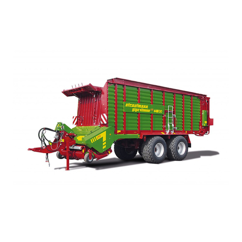
Strautmann Giga-Vitesse CFS 3602 User manual

Strautmann
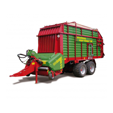
Strautmann Super-Vitesse CFS 3101 User manual

Strautmann
Strautmann Mega Trailer II User manual

Strautmann
Strautmann Verti-Mix SF Quick guide

Strautmann
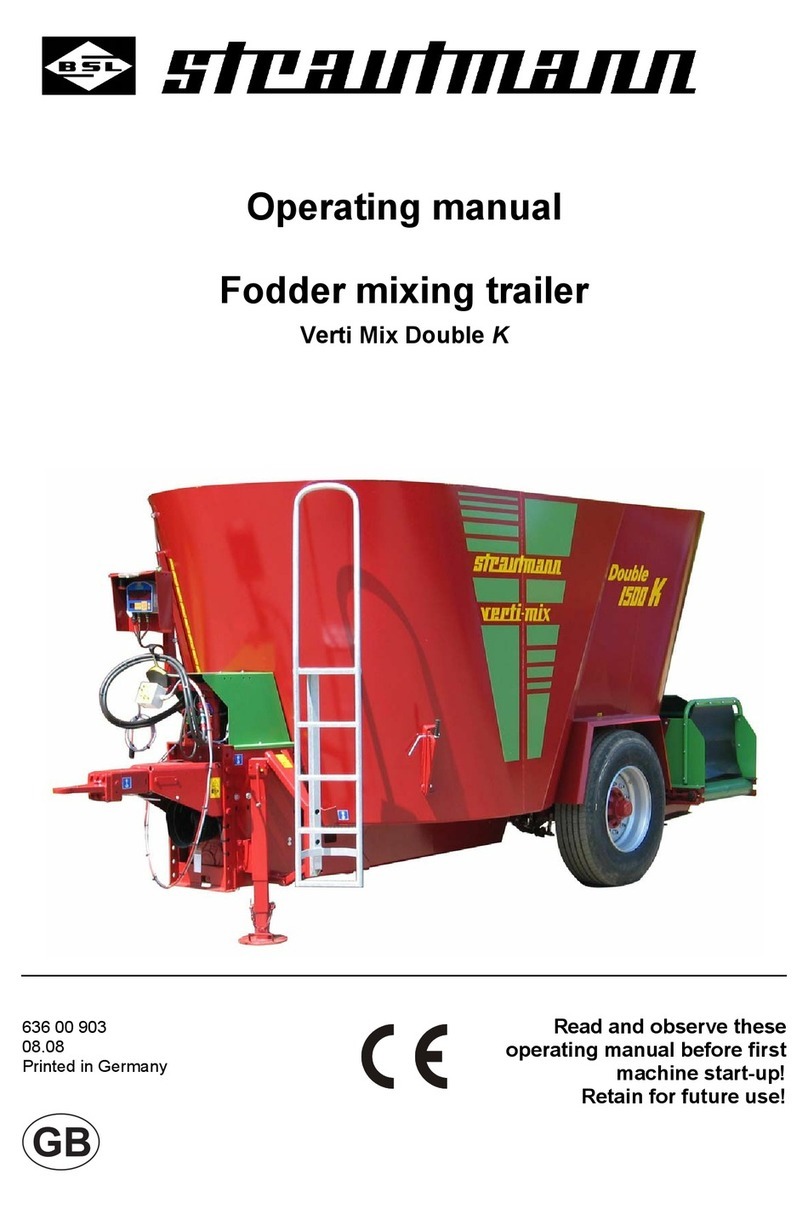
Strautmann Verti Mix Double K User manual

Strautmann
Strautmann Sherpa 120 User manual

Strautmann
Strautmann Verti-Mix 3451 User manual