BIG BALE Transtacker Standard User manual
Operation and Maintenance Manual
It is the responsibility of the operator to read and understand the contents of this manual before
operating the machine for the first time.
The Operators manual must accompany the machine at all times. If the machine is resold the
Operators manual must be given with the machine to the new owners.
Please read and follow all instructions before operating the machine

2

Contents
4. 1.0 INTRODUCTION
5. 2.0 SPECIFICATION
6. 3.0 MACHINE OVERVIEW
7. 4.0 SAFETY
9. 5.0 OPERATION
25. 6.0 ADJUSTMENTS
29. 7.0 TROUBLE SHOOTING
31. 8.0 MAINTENANCE
32. 9.0 WARRANTY
33. 10.0 ELECTRICAL &HYDRAULIC SYSTEMS
3
Page Title

1.0 Introduction
1.1 Description
In choosing the Big Bale Transtacker you have purchased
amachine of exceptional versatility.
This manual should be regarded as essential reading in the
interest of safety, efficiency and longevity of the machine.
References to Right and Left in this manual are taken as
viewing the machine from the rear facing in the normal
direction of travel.
1.3 Machine Identification Plate
If service parts are required it is necessary to quote the
machine serial number.This is located at the front right
hand side of the machine on top of the drawbar front plate.
It is recommended that this information be transferred to
this page on delivery of the Big Bale Transtacker.
Model ________________________
Serial No. ________________________
Year of Manufacture ________________________
Date of Delivery ________________________
Unladen Weight ________________________
Max Gross Weight ________________________
Max Drawbar Load ________________________
1.2 SAFETY ALERT SYMBOLS
This warning symbol appears throughout this hand book.
Attention is drawn to items or operations that could cause
danger to the operator or to persons nearby.Please read
safety messages carefully and have a full understanding of
their importance.
Always abide by the requirements.
WARNING: Warnings call attention to instructions, which
need to be followed precisely to avoid a hazardous
situation.
CAUTION: Cautions call attention to instructions, which
must be followed precisely to avoid damaging the product,
process or surroundings.
4
CHK PLC
MODEL
PYMS LANE,
CREWE,
CHESHIRE CW1 3PJ,
UNITED KINGDOM
TEL: 0044(0) 1270 252894
SERIAL No.
YEAR OF Man.
UNLADEN WEIGHT
MAX GROSS WEIGHT
MAX DRAWBAR LOAD
Kg
Kg
Kg
Fig. 1
1.4 Intended Use of the Machine
The Big Bale Transtacker is designed to assemble various
sized big bales, 2.4m (8') long, into completed stacks and
erect them into a tower.
The various sizes of bales must have a width or depth
which can, (when arranged side by side in some multiple),
form a rectangle that is 2.4m(8') square. Bale length is
permitted to vary considerably but to tie layers, 2.4m ± 0.1
is preferred.
The machine will also recover previously erected towers
and re-erect them in a new location.
The bales can be of various straws and hays generally
found in agricultural use.
The machine is generally towed with an agricultural tractor
recommended minimum of 6 Tonnes,140 HP.

1.0 Introduction
1.7 Accessories and Attachments
High Speed Axles
Above 30 kph (20 mph), A.B.S. with air brakes may be
required. This can be specified on the initial purchase
specification but can also be retro fitted at extra cost.
It is important to note that high-speed use on highways may
be restricted by a machine width in excess of 2.55 m.
Flashing Beacon
A flashing beacon can be mounted on the panel adjacent to
the number plate. When fitted in conjunction with a tractor
cab top mounted unit, it provides all round visible flashing
lights (Fig. 2).
Hydraulic Pickup Adjuster
For operators who regularly change the bale size, a
hydraulic pickup adjuster is fitted as standard to ease and
speed up pickup height adjustment.
5
2.0 Specification
Big Bale Transtacker Standard Big Bale Transtacker Extra
Length 10.3m 10.7m
Height 3.7m - 4.1m 3.7m - 4.1m
Automation Semi automatic pick up and stack Semi automatic pick up and stack
80 x 90 x 240 - MF2150 21 24
120 x 70 x 240 - MF2160 18 20
120 x 90 x 240 - MF2170 14 16
120 x 127 x 240 - MF2190* 10 12
Unladen weight 7.0 Tonnes 7.5 Tonnes
Maximum Load 8.0 Tonnes 9.0 Tonnes
Wheels / Tyres (+ sizes) 560/60-22.5 12PR 560/60-22.5 12PR
Oil Supply Required 60L/min @ 3000psi 60L/min @ 3000psi
Electrical Supply Required 30 Amp 12V DC 30 Amp 12V DC
Brakes 4 wheel hydraulic as standard 4 wheel hydraulic as standard
Brake options ABS air,ABS air/hydraulic, TUV air ABS air, ABS air/hydraulic, TUV air
Other options** Bed rollers - Sprung drawbar Scharmuller coupling Bed rollers - Sprung drawbar Scharmuller coupling
*Including additional layer **Some options for non UK models only
Fig. 2
Fig. 3
1.5 Construction and Use Act UK
The machine can be classed as an agricultural appliance
provided the load does not exceed its unladen weight.
1.6 Noise Declaration
Sound Pressure Level
The sound pressure level of the Big Bale Transtacker does
not exceed 70 dB (A).

A
L
N
SOQ
P
R
T
V
D
C
U
E
K
J
I
H
M
F
B
G
G
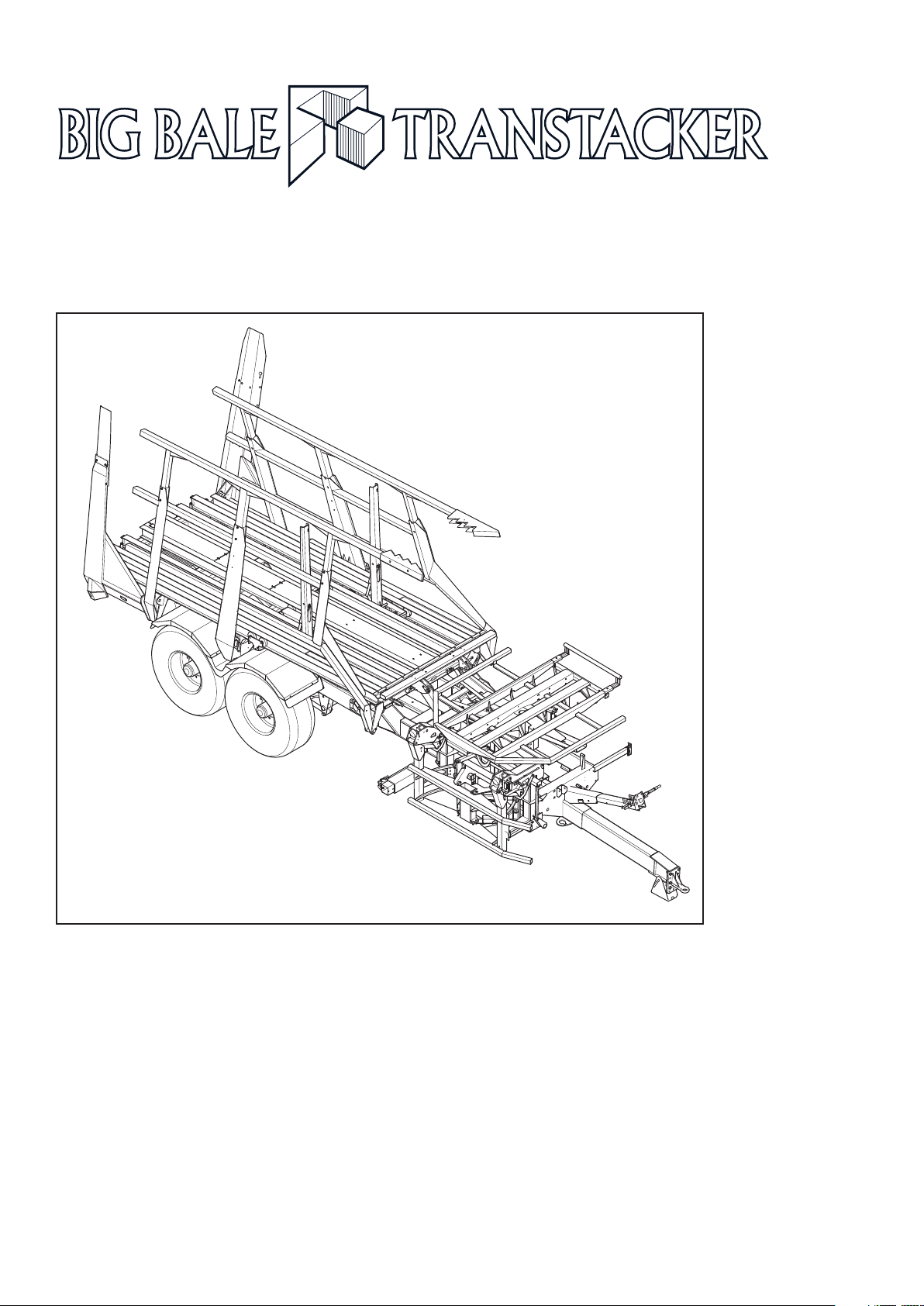
3.0 Machine Overview
6
ARear Clamp
BRear Clamp Beam
CRear Clamp Pads
D Side Gates
EForks
FPlatform Extension
G Location of Parkbrake
HBale Stop
IHooks
JTurn Table
KService Post
L Drawbar
MPickup Latch Indicator
NPickup Latch
OPickup Frame
P Pickup Guide Rails
QPickup Tines
RGuide Bar
SLatch Cable
TChassis
USide Clamp Beam
VPlatform
Fig. 4

4.0 Safety
4.1 Safety in Operation & Maintenance
Operation of the machine without paying heed to fitting and
use of guards or to the safety notices renders you liable to
prosecution.
This applies even if you are the injured party.
Your attention is drawn to the safety notices (decals) that
are displayed on the machine. These notices should be kept
clean and intact so they are legible at all times.
If any of the notices become detached or defaced, they
must be replaced immediately.
These are available from your local Big Bale Transtacker
agent.
They are included in the spare parts list and examples to
aid identification are reproduced on the following pages.
WARNING: Read Owners Manual
This manual contains safety information and
operation and maintenance instructions for your Big Bale
Transtacker. The operator must ensure that he/she has fully
read and understood this manual before operating the
machine.
WARNING: Before Commencing Any
Repairs/Maintenance
Shut off engine, remove ignition key, and unplug electric
control box before performing any maintenance or repair
work.
WARNING:
Keep persons away from the machine during operation.
There is a danger from falling bales and moving machinery.
WARNING:
When the pickup guide is out there is a danger that it may
be overlooked by the operator. A flashing light and audible
signal on the control box indicates the guide is out. An
indicator on the pickup latch signals that the guide is in and
the pickup is locked in position (Fig. 5).
WARNING:
Do not raise the platform of the Transtacker while under
high voltage power lines. Some parts of the machine can
exceed 5.2m high and cause electrocution and/or fire.
7
Fig. 5

4.0 Safety
WARNING: Keep clamp side pins in place when
transporting on highways.
When travelling along roads the side clamps are subject to
variable and high loads. Failure or inadvertent operation of
the side clamps could cause very serious injury or damage
to others. Set controls to ‘Road Mode’ prior to road
transport (Fig. 6)
Failure of the hydraulic lines is covered by the load valves
attached to the clamp and lift cylinders. Road Mode should
be used during transport to prevent inadvertent operation.
The safety pins provide a necessary and useful further
safety device should there be a failure of the cylinder.
WARNING:
Take care when operating on sloping ground or when
traversing undulations at speed to prevent overturning of the
stacker. By necessity the machines have a high centre of
gravity when loaded. Caution should always be exercised to
prevent overturning and resulting injury and/or damage.
When picking up bales on sloping ground, always traverse
the slope so that the bales are picked up from the high
(right hand) side.
8
Fig. 6
Road Mode

5.0 Operation
5.1 Attachment to the Tractor
Drawbar
Requirements
The drawbar is normally supplied with a ring hitch, which is
suitable for connection to the pickup hitch found on most
tractors in the UK.
Ensure that your tractor hitch is suitable for this type and
dimension of ring.
Ensure the capacity is a minimum of 3 Tonnes. Additionally,
the recommended minimum horsepower is 140 HP and 6
Tonnes weight.
An oil supply of at least 60 L/min @ 200 bar (8.79
Gallons/min (UK) @ 2900 psi) and a minimum electric
supply of 20 Amps @ 12v DC are required. The tractor must
be fitted with a power beyond unit.
Attaching
Hitch the tractor to the machine. Remove and store the
drawbar stand and pin. The machine should now sit
approximately level at the chassis.
Turn the tractor cautiously and ensure the tractor links etc
do not foul on any part of the machine and that there is
sufficient clearance for hoses etc. Remove links if
necessary.
Connect the brakes to the tractor and ensure correct
operation.
Release the hand brake (Fig. 7),which is under the front
left of the chassis, and obtain assistance to check the
operation of the trailer brake cylinders when the brake pedal
is depressed.
Ensure the tractor lighting voltage is 12 v DC before
connecting the lights.
Connect the lights via the 7-pin plug stored just off centre of
the service post and confirm correct operation.
Tractor connections and identification colours are as follows;
(Fig. 8)
Hose 2 – Pressure – Red - 3/4” Hose
Hose 3 – Return – Blue – 1” Hose
Hose 4 – Load Sense – Yellow – 1/4” Hose
Hose 5 – Pilot drain – Blue- 1/4” Hose
For tractors with only three connections available hoses 3 &
5may be joined together using a tee piece at the tractor
end.
Please ensure that the above connections to the tractor’s
power beyond unit are made in accordance with your
Tractor Manufacturers instructions and Guidelines.
9
Fig. 7
Tank
Blue
No. 5
1/4” Hose
No. 3
1” Hose
No. 1
3/4” Hose
No. 4
1/4” Hose
Tank Pressure Load Sense
Blue Red Yellow
No. 2 3/4” Hose
F1
10
Micron
Fig. 8
WARNING: Oil under pressure can penetrate skin. Seek
medical advice involving any incident where this may occur.
Oil is an irritant. Wear protective gloves when handling.
CAUTION: Ensure the tractor will supply at least 60 L/min
@200 bar (8.79 Gallons/min (UK) @ 2900 psi and does not
exceed 80 L/min (17.6 Gallons/min (UK)).
Set the flow at 40-50 L/min. (8.79 - 11.0 Gallons/min (UK)).
5.2 Hydraulics

5.0 Operation
5.3 Electrical
Mounting the Control Box
Mount the control box securely in the tractor cab in a
position that suits you (Fig. 9).
Do not obstruct access to hydraulic levers or other
important controls;
Easy comfortable operation of the joystick and push button
switches is preferable;
Maintain good visibility of the control box lights and decal;
The operator will be most likely observing the pickup over
his right shoulder;
The seat may traverse up and down considerably on rough
ground.
When the control box is mounted, connect it to the tractor
electrical supply via the lead provided. Ensure that the
voltage is correct, 12v DC and that the fused wire is positive
(Fig. 10).
If the control box is connected through sockets provided in
the tractor, ensure they and any fuses are capable of 20
amps continuous supply.
It is recommended to connect the lead provided to the
tractor battery. This is pre fitted with a 20 amp blade fuse.
When the control box is mounted and working, switch off
and connect to the machine using the multi core cable
provided. Carefully connect one end to the base of the
control box. The other end is connected to the junction box,
which is mounted on the chassis rail mid machine (Fig. 11).
Note: this junction box is placed ideally to protect it from the
elements at all times. Loop the cable around after threading
through the front drawbar plate to assist fitting. Do not forget
to thread the cable through the service post and any cab
entry points. Finally secure the cable to the hydraulic hoses
to prevent damage and store surplus cable inside the cab.
CAUTION: The power should be switched off to the control
box via the switch at the rear if the machine is not being
used for long periods (Fig. 11).
The control box and joystick should connect using the cable
provided and the control cable then connected to the main
trailer cable.
10
A
B
C
D
ELE-20120-40
Connection for
Loom to Trailer
Connection for
Loom to joystick
Connection Point
for ELE-20120-80
ELE-20120-02
Rear View ELE-20120-02
ELE-20120-01
ELE-20120-05
Connection to Battery
Including 30A Fuse
ELE-20120-06
ELE-20120-07
Connection for
Joystick to Display
ELE-20120-01
ELE-20120-03
Fig. 9
Fig. 11
Fig. 10
Reset Button

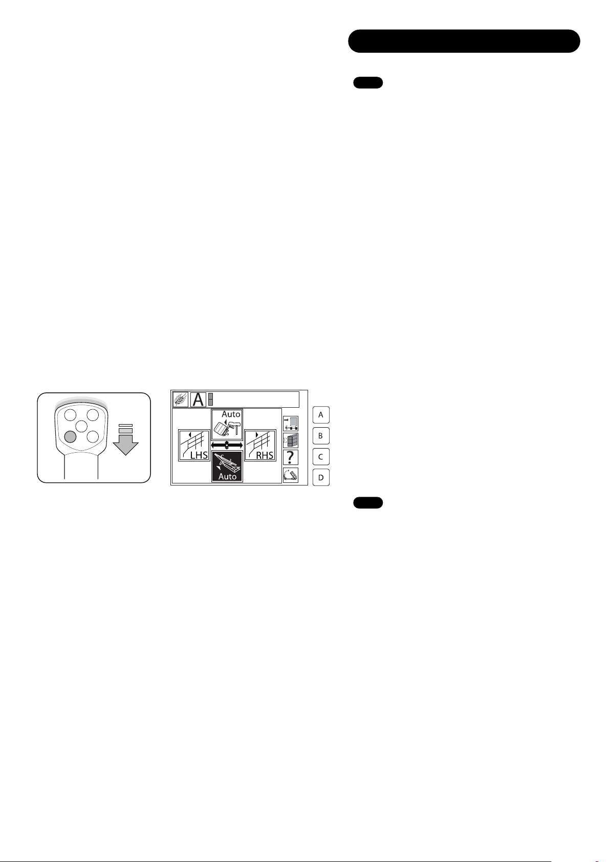
5.0 Operation
5.4 Joystick functions
11
Fig. 13
Button Joystick position Function in Field Mode Function Stack Mode
Y+ Auto Pickup Main tip down
None Y-Auto stack with tie Main tip up
X+ RHS gate open RHS gate open
X- LHS gate open LHS gate open
Y+ Auto open Auto tip down
1 Y- Auto stack no tie Auto open
X+ RHS gate close RHS gate close
X- LHS gate close LHS gate close
Y+ Auto table down Hooks out
2 Y- Centre clamps open Centre clamps open
X+ Guide bar out Turntable extend
X- Guide bar in Turntable down
Y+ Pickup tines in Drawbar down
3 Y- Pickup lower Drawbar up
X+ Pickup tines out Table turn
X- Pickup lift Table return
Y+ Forks up Turntable up
4 Y- Hooks in Centre clamps close
X+ Hooks out Hooks out
X- Forks forward Turntable retract
3
41
Road Mode Direction
of Travel
Y+
Y-
X- X+
2
Pressing ‘?’ will bring up text prompts for functions
Fig. 12
5.0 Operation
5.5 Controls
WARNING: Keep persons away from the machine while
operating. There is a danger from falling bales and moving
machinery.
CAUTION: When picking up the bales laid across sloping
ground, always traverse below the bale to ensure stability of
the stacking machine during pickup cycles.
Getting Started
Having entered the field, stop and set the machine ready to
operate as follows:
1. Exit ‘Road Mode’ by pressing and holding the
green button on the base of the joystick for 2 seconds
(Fig. 14).
2. Enter Field mode if required by pressing Button ‘D’ or the
top right button on the joystick (Fig. 15).
3. ‘Auto Open’ the clamps by pressing the bottom left button
and pushing forward on the joystick (Fig. 16).The guide will
also extend out fully. This should release the latch
mechanism. Check the guide light is flashing and the latch
pointer is aligned with the yellow sector of the decal
(Fig. 17).
Fig. 17 Note 1
If auto pickup is activated when the guide is in it wont work.
Fig. 17 Note 2
The Dotted Line position indicates the guide is out and the
pickup is free to operate.
Fig. 17 Note 3
The Pointer indicates that the guide is in and the pickup is
locked and ready for transport.
The indicator can in some circumstances indicate that the
guide is in. Whereas in fact the pickup has not been used
and has locked the latch in the transport position. Operate
the pick up return to check.
4. The forks (on newly delivered machines) will be bolted
down. If fork operation is required, undo these bolts. See
6.4 Use of Forks - page 26.If not, ignore Instruction 5 and
proceed to instruction 6.
5. Hold down the bottom right button and push the joystick
forwards (Fig. 18) to bring the forks up. Keep the bottom
right button held down and move the joystick left (Fig. 19),
this will bring the forks to the front of the platform ready to
support the first bales.
12
Road Mode
Indicates ‘Field mode’ active
Or
Fig. 14
Fig. 15
Fig. 16
12
Fig. 17
Fig. 18
Fig. 19
5.0 Operation
5.5 Controls Cont..
6. Drive along side the first bale. (Select a bale that is on
flat ground). Drive forward until the guide is pushing the
bale along the ground and having turned towards the bale, it
should be tight against the pickup rails (Fig. 20).
Fig. 20 Note 1
The bales should come to rest firmly against the guide.
Fig. 20 Note 2
Turning towards the bale as you pass it will ensure the bale
is kept tight against the guide rails.
1. Drive close along side the bales (it may be beneficial to
turn into the bale as the tractor passes, to ensure the bale
fits tight against the pickup rails), when the bale is in the
correct position, push forward on the joystick (Fig. 21).The
machine will automatically pick up the bale and place it on
the table, before returning to its original position (Fig. 22).
Caution: It is important that the tractor engine is turning fast
enough to maintain a full flow of oil to the machine during
automatic cycles. Select a gear that is best suited to engine
rpm and the distance between the bales. There is no
theoretical limit to the speed at which bales can be picked
up but some damage to bales may occur above (6 mph)
10kph.
13
1
2
Fig. 20
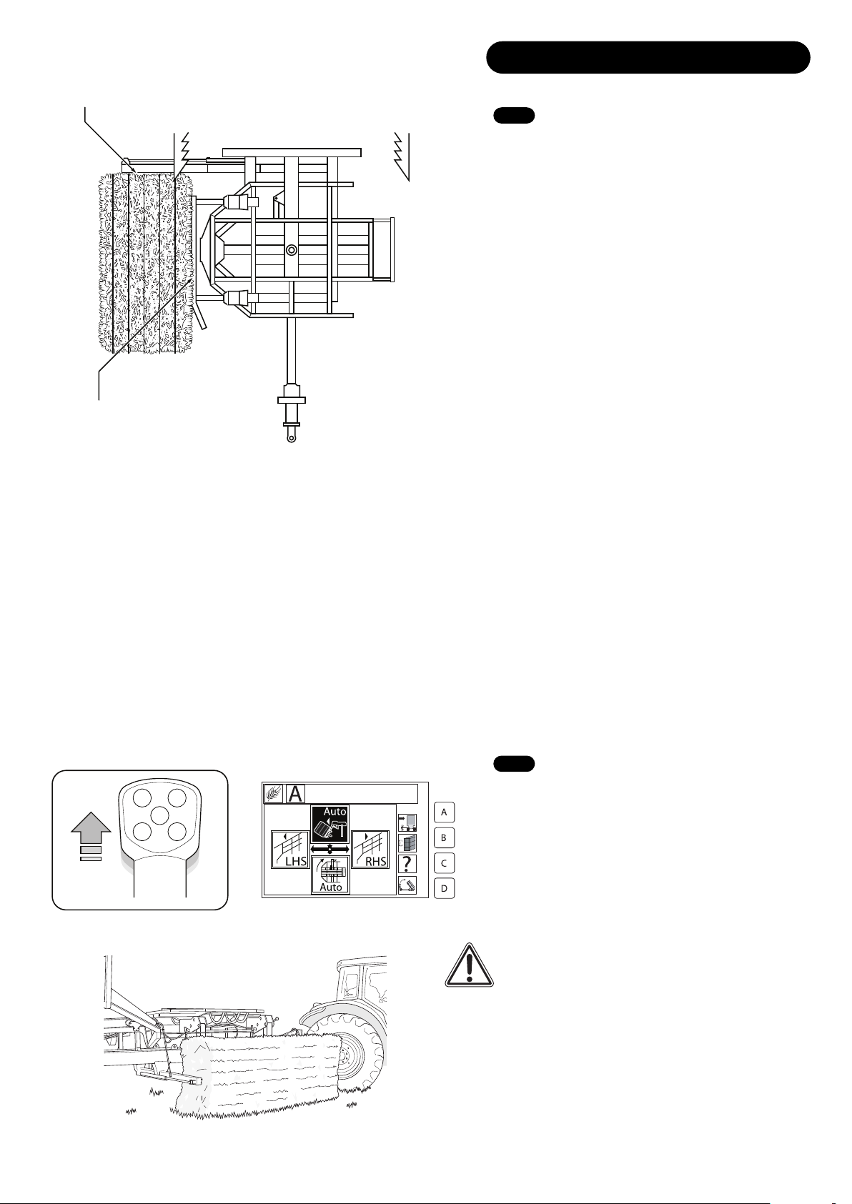
5.6 Pickup (Automatic)
Fig. 22
Fig. 21
2. Approach the next bales in the same manner and repeat
the pickup cycle. Depending upon bale size, it will be noted
that the hooked table will be full after 2 or 3 bales (Fig. 23).
3. The last bale onto the table will push the first against the
stop bar and will squeeze the bales tight together. If for
some reason the bales are not aligned correctly then
re-pressing forward on the joystick (with the pickup at the
top of its cycle) will cause the pickup to return, with the bale,
towards the ground. Releasing the joystick will resume the
pickup cycle and thus effect a re-cycle. This is necessary
with bales of an extreme rectangular shape, to ensure good
and tight alignment of the bales on the hooked table.
Note: You can manually override the automatic pickup cycle
at any stage.
Note: See 6.1 page 25 for correct height adjustment.
5.0 Operation
5.6 Pickup (Automatic) Cont.
14
Fig. 23
Fig. 24
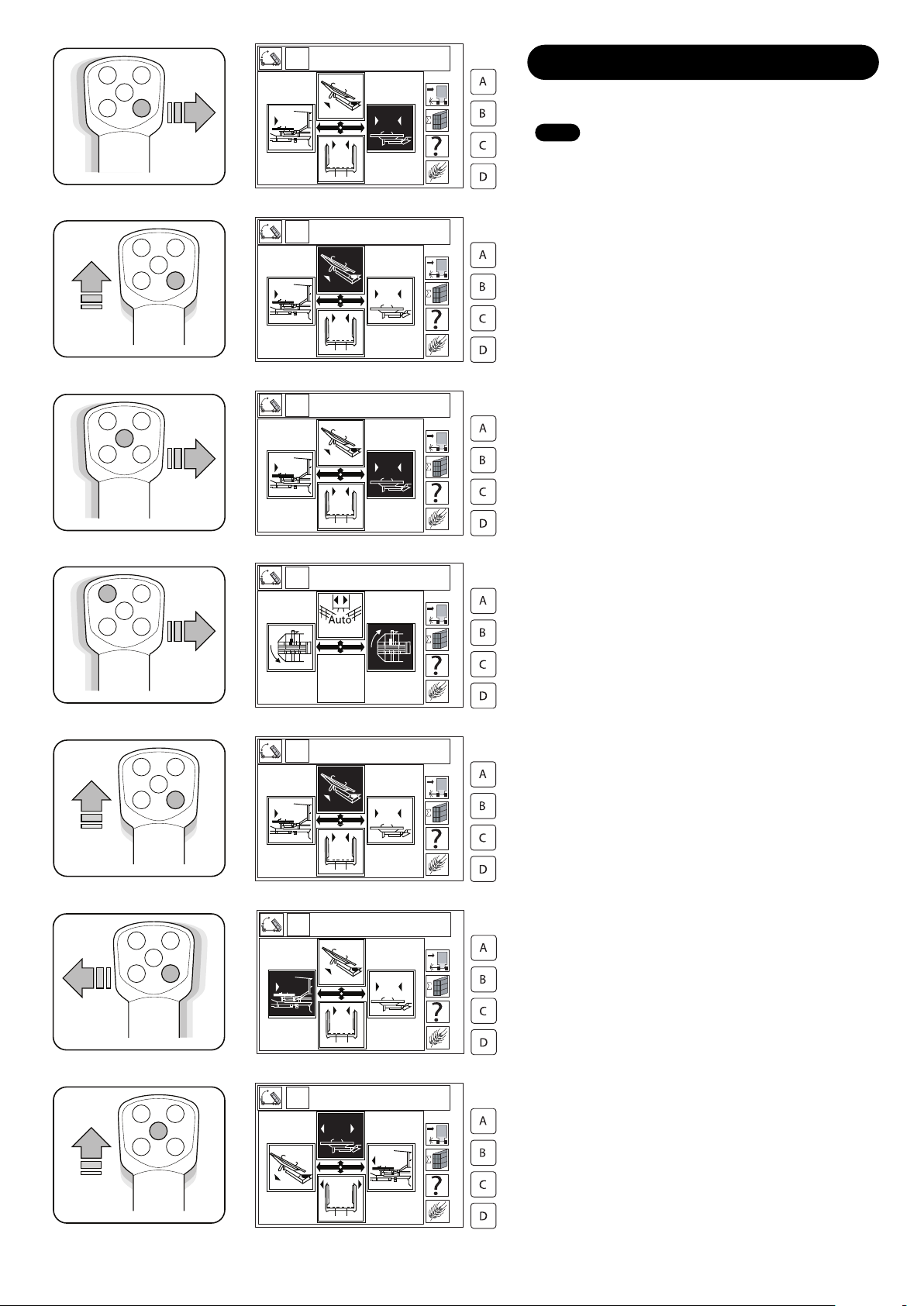
5.7 Pickup (Manual)
1. Follow the instructions as for the Pickup (Automatic).
2. When the bale is in the correct position, hold down the
top left button and push the joystick right (Fig. 24) until the
tines penetrate the bale sufficiently.
3. When it is considered that the tines are in sufficiently,
keep the top left button held down and push the joystick
forward (Fig. 25) and the pickup will raise the bale.
4. When the pickup is at the top of its stroke, stop pushing
the joystick forward, keep holding down the top left button
and move the joystick left (Fig. 26) to withdraw the tines.
As the tines move out of the bale, keep the top left button
held down and pull the joystick back (Fig. 27) to bring the
pickup back to its start position.
Fig. 25
Fig. 26
Fig. 27

5.0 Operation
5.8 Stacking (Automatic)
1. Before operating the stacking function, ensure the
following:
A. The pickup has returned fully (Fig. 28).
B. The table is full and the bales are tight, central and well
aligned. This is very important (Fig. 29).
Fig. 29 Note 1
Note the alignment with the sides of the platform.
Fig. 29 Note 2
The Bales must be tightly packed together, tight up against
the bale stop and central to the machine.
Fig. 29 Note 3
Location of Bale Stop.
C. Ensure the forks are erect, pressurised and forward
enough to support the first layer of bales if required -
(optional depending on bale size).
See 6.3 Stacking adjustments page 26.
D. Check the rear clamp is fully open and the sides are
approximately vertical and parallel.
See 5.5 Getting Started page 12.
E. Ensure you are still in Field mode (Fig. 30).
2. Pull the joystick back (Fig. 31) and the machine will place
the first line of bales on the platform against the forks and
return to its lower position on the nylon bottom stops with
the hooks withdrawn.
See 5.9 Using the Tie Function page 16.
3. The sprung loaded bale keeps should grip the bales and
prevent them falling forward but allow easy sliding of the
bales into the platform. Adjust the sides as necessary.
4. View the Screen on the control panel, this will have
progressed to indicate one layer of bales (Fig. 32).
5. Repeat the above process until the platform is full. This
will be indicated by the LCD flashing full.
15
12 3
Fig. 29
Pick up
Fig. 28
Fig. 30
Fig. 32
Fig. 31
Indicates ‘Field mode’ active
Indicates one layer of bales
5.0 Operation
5.9 Using the Tie Function
To secure completed towers it is necessary to tie at least
one layer during the stacking operation.
1. The tie cycle adds to the stacking cycle time so keep
tying to a minimum.
2. The complete tower is more secure and weather proof
with the tied layer in the top half of the tower.
3. Subsequent handling of the bales may require the top 2
or 3 layers to be picked off together.
4. Turning the first layer of bales may permit simpler,
quicker stacking without the use of the forks. This is
particularly applicable with deep bales. (80-130cm.)
5. The length of bales in a tied layer must be 2.4m ± 0.1m
otherwise they will jam during stacking or make the resulting
stack unstable. If bale length is not correct then it is best to
tie the last layer i.e. the layer at the top of the resulting
tower.
6. If the first/bottom layer is tied there may be problems
experienced erecting the finished tower if bale length is
widely variable.
7. One layer will need to be tied for successful stack
transportation.
Follow the instructions for Stacking (Automatic) but press
the bottom left button and pull the joystick back (Fig. 33).
The machine will complete a stack cycle with tie.
5.10 Combined Pickup and Stack (Automatic)
If AUTO PICKUP is depressed during a stacking cycle the
pickup will take priority and will hold mid cycle until the
stacking cycle is completed. The pickup will automatically
finish its cycle when the stacking is finished. The height at
which the pickup holds the bale during stacking is controlled
by the Pickup Hold Timer.
(See 6.9 Control Box Timers, Page 28).
This feature is designed to smooth and speed up the bale
gathering process.
16
Fig. 33

5.0 Operation
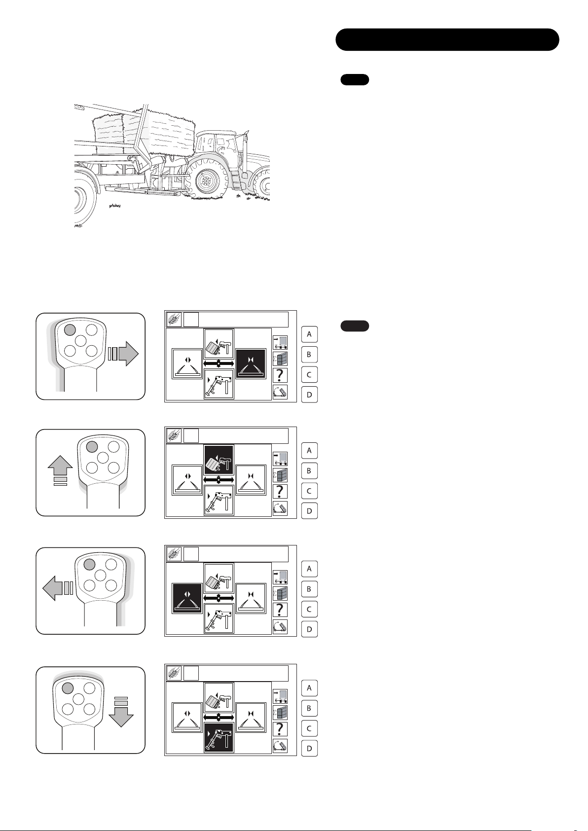
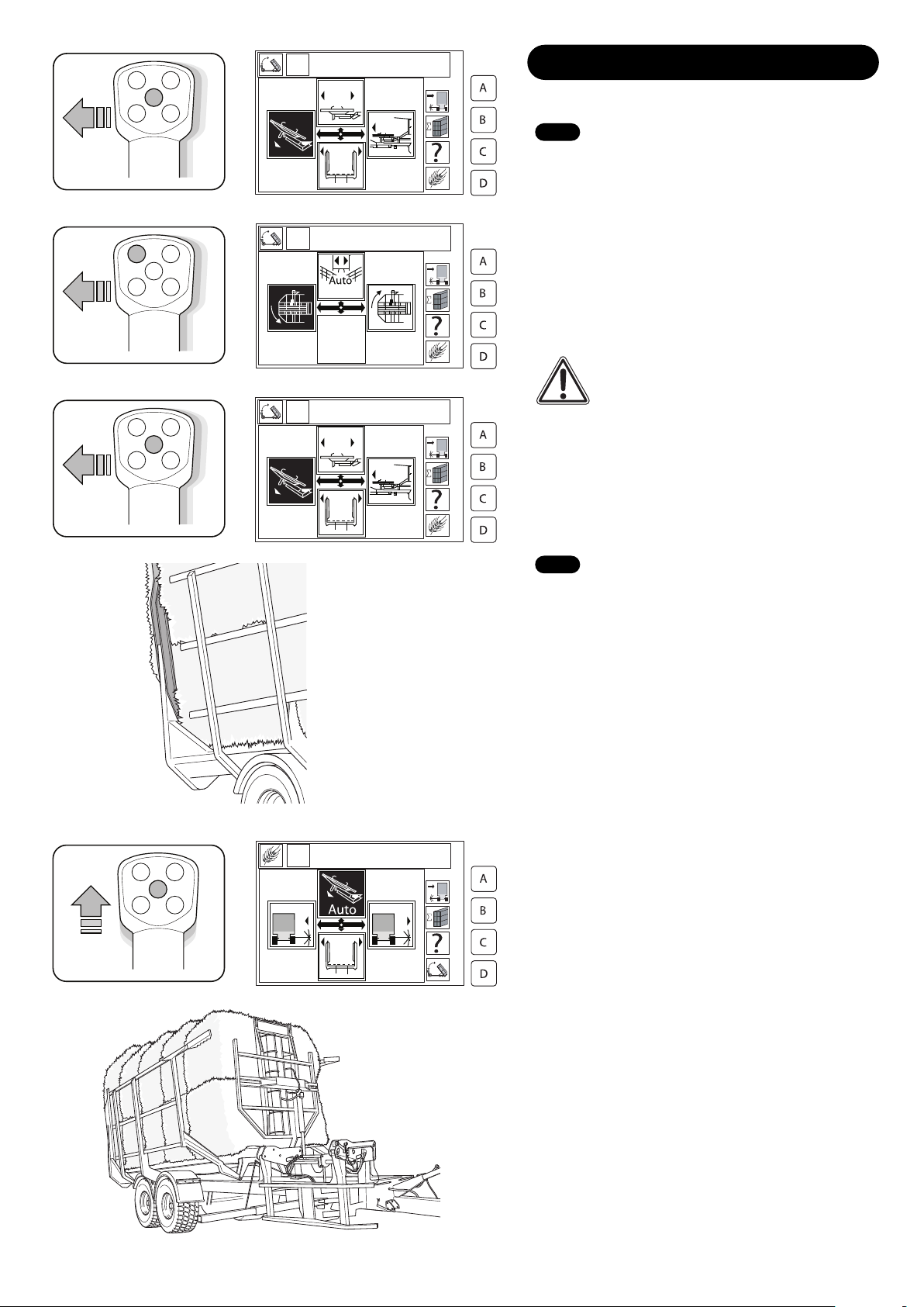
5.11 Stacking (Manual)
WARNING: While it is possible to stack manually,
it is recommended to auto stack. Unless operated
by a competent user, it is likely the machine could
get damaged.
A. Ensure you are in Stack mode.
1. Carry out the same checks as in Stacking (Automatic).
2. Press the bottom right button and push the joystick to the
right (Fig. 34) to hook the bales.
3. Press the bottom right button and move the joystick
forward (Fig. 35) and hold until the table is fully raised and
the bales are positioned on the platform (Fig. 36).
4. Hold down the middle button and push the joystick forward
(Fig. 37), hold until the hooks are fully out.
5. Hold down the middle button and push the joystick left
(Fig. 38), hold until the table returns to its bottom nylon
stops.
17
Fig. 36
Fig. 34
Fig. 35
Fig. 37
Fig. 38
5.0 Operation
18
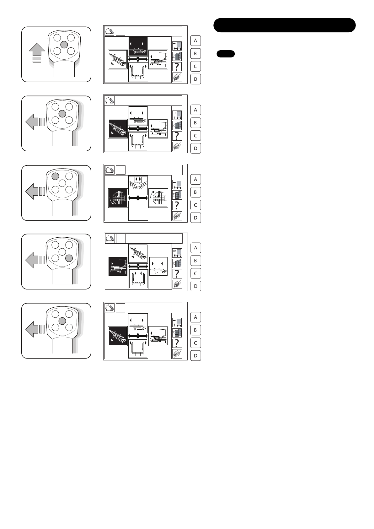
5.12 The stacking cycle is complete.
To manually tie a layer
A. Ensure you are in Stack mode.
1. Carry out the same checks as in Stacking (Automatic).
2. Hold down the bottom right button and move the joystick
right (Fig. 39) to hook the bales.
3. Hold down the bottom right button and move the joystick
forward (Fig. 40) momentarily to lift the table clear of the
pickup.
4. Hold down the middle button and move the joystick right
(Fig. 41) until the table is forward approximately 150-
300mm and clear of its bottom nylon stops. Hold down the
top left button and push the joystick right (Fig. 42) until the
table is fully rotated 90°.
5. Hold down the bottom right button and move the joystick
forward (Fig. 43) until the table is fully erect.
6. Hold down the bottom right button and push the joystick
left (Fig. 44) until the table is fully retracted.
7. Hold down the middle button and push the joystick
forward (Fig. 45) until the hooks are out.
Fig. 39
Fig. 40
Fig. 41
Fig. 42
Fig. 43
Fig. 44
Fig. 45
5.0 Operation
5.13 Finishing a Stack
When the platform is full a sensor on the rear of the
platform will signal and illuminate the LCD.
The stacking cycle will stop and the rear clamp will
automatically clamp the bales (Fig. 49).This will be
indicated by a flashing ‘FULL’, followed by a constant
‘FULL’, when the bales are clamped.
1. If the table has returned to bottom stops, proceed to
pickup bales. Ensure more bales will clear the bales already
in the platform.
2. If the table has not descended then hold down the middle
button and push the joystick forward (Fig. 50). If the table
descends, more bales can be loaded. If it does not then the
machine is full and the completed tower must be erected
before more bales can be loaded (Fig. 51).
19
Fig. 49
Fig. 50
5.12 The stacking cycle is complete.
To manually tie a layer Cont.
8. Hold down the middle button and move the joystick left
(Fig. 46) to lower the table away from the bales to a point
not fully lowered.
9. Hold down the top right button and move the joystick right
(Fig. 47) until the table is straight.
CAUTION: The table must not be rotated in its
fully lowered position or damage may occur.
10. Hold down the middle button and move the joystick left
(Fig. 48) to return the table to its bottom stops.
Fig. 46
Fig. 47
Fig. 48
Fig. 51
Operation
5.0 Operation
20
5.13 Finishing a Stack Cont.
4. If the table has not descended but it is considered more
bales can be loaded then proceed as follows:
ensure you are in Stack mode.Hold down the middle button
and push forward on the joystick (Fig. 52) to retract the
hooks. Hold down the middle button and push left on the
joystick (Fig. 53) to half lower the table, then hold down the
top left button and push the joystick left (Fig. 54) to return
the table to its fully returned position.
5. Hold down the bottom right button and move the joystick
left (Fig. 55) to fully retract the extension. Hold down the
middle button and move the joystick left (Fig. 56) to fully
lower the table. Now more bales can be loaded.
6. Ensure the extension timer is set to the bale size used
(see 6.9 Control Box Timers, page 28). Some manual
input may be required to position the final layer of bales
firmly against the stack.
Fig. 52
Fig. 53
Fig. 54
Fig. 55
Fig. 56
This manual suits for next models
1
Table of contents
Other BIG BALE Farm Equipment manuals

Popular Farm Equipment manuals by other brands

Kongskilde
Kongskilde R 365 DS Operator's manual

Westeel
Westeel WaterTank Flat Roof Installation and Storage Instructions

Frontier
Frontier DH1276 Operator's manual

Gude
Gude GGF 620 Translation of the original instructions

Gaspardo
Gaspardo Primo E2 Use and maintenance

Land Pride
Land Pride REAR BLADES RBT55120 Operator's manual

Kverneland
Kverneland 4328LT Service manual

CrustBuster
CrustBuster Speed King owner's manual

Cima
Cima Link Operation and maintenance instruction

Sovema
Sovema PL 180 Operation and maintenance manual

AGCO
AGCO Laverda Combines M400 Operator's manual

Ag Leader Technology
Ag Leader Technology CaseIH 2055 manual


