Big Daishowa DynaForce User manual

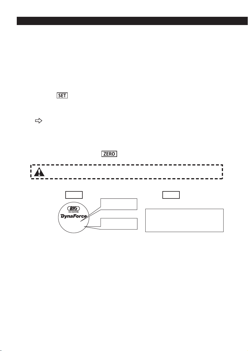
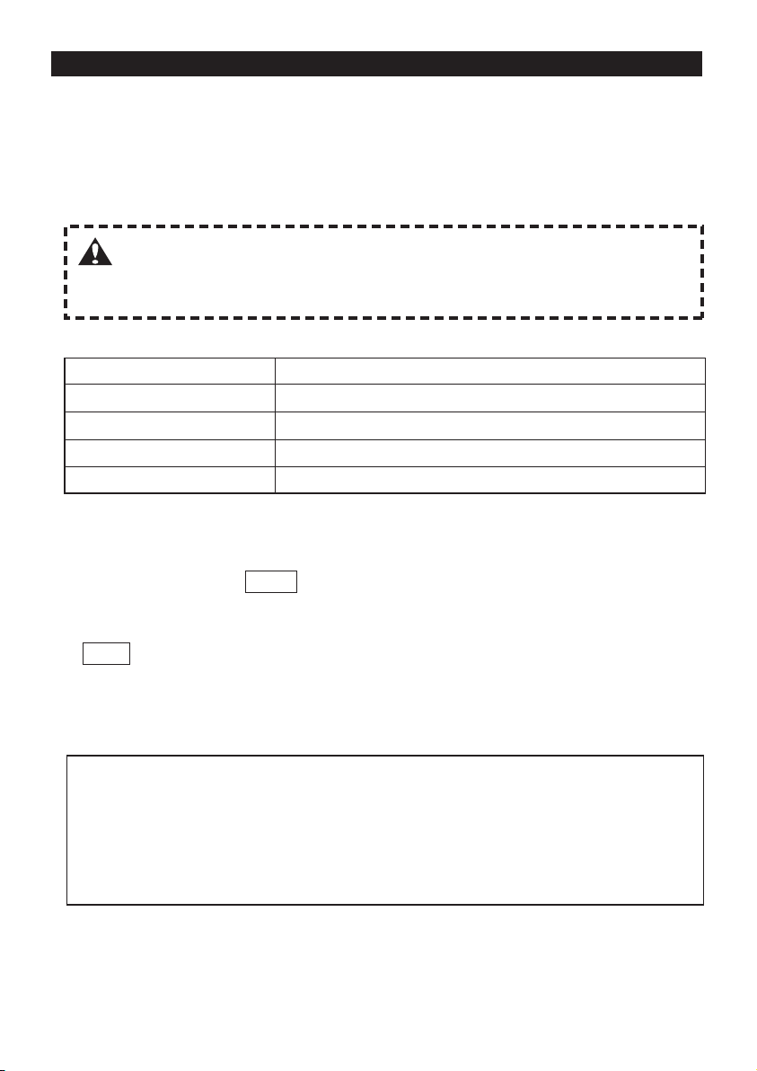
PEAK
HOLD
ZERO SET
kN
TYPE : DFA-1
TYPE : DFA-1
測定器毎の感度校正登録が必要です。
測定時はスイッチを「MEAS」に入れ、「kN」表示にしてください。
It is necessary to calibrate each measuring device.
Select[MEAS] position and indicate [kN] on the display
before starting measuring.
取扱説明書
ダイナフォース
OPERATION MANUAL
Read the operation manual before use.
ご使用前には必ず本書をお読みください

●INDEX●
1仕様
1-1各部の名称
2測定方法
2-1プルボルトの取付け
2-2測定器と表示器の接続
2-3電源の投入
2-4ゼロリセット
2-5機械主軸への取付け
2-6ピークホールド測定
2-7測定終了
2-8電池交換
・・・・・・・・・・・・・・・・・・・・・・・P1
・・・・・・・・・・・・・・・・P2
・・・・・・・・・・・・・・P2
・・・・・・・・・・・・・・・・・・・・・・・・P2
・・・・・・・・・・・・・・・・・・・・・・P2
・・・・・・・・・・・・・・・・P3
・・・・・・・・・・・・・・・・P3
・・・・・・・・・・・・・・・・・・・・・・・・・・P3
・・・・・・・・・・・・・・・・・・・・・・・・・・P3
3表示器の設定方法
3-1感度校正の確認
3-2感度校正登録[F3]
3-3ローパワー[F5]
3-4コントラスト[F-14]
4補足説明
4-1設定モード変更方法
4-2設定モード一覧
4-3エラー表示
4-4バッテリー電圧低下表示
5使用上のご注意
・・・・・・・・・・・・・・・・・・・・P4
・・・・・・・・・・・・・・・・・P4
・・・・・・・・・・・・・・・・・・・P6
・・・・・・・・・・・・・・・P6
・・・・・・・・・・・・・・・・P7
・・・・・・・・・・・・・・・・・・・・P7
・・・・・・・・・・・・・・・・・・・・・・・・P8
・・・・・・・・・・・・P8
・・・・・・・・・・・・・・・・・・・・・・・・・P9
この度は、 ダイナフォースをお買い求めいただき誠にありがとうございます。
ご使用前には必ず本書をお読みいただき、ご使用される方全員がいつでも見ることが
できる場所に必ず保管してくださいますようお願いいたします。
1 Specifications
1-1 Descriptions
2 How to measure
2-1 Installation of pullstud
2-2
Connection between measuring
device and display unit
2-3 Power activation
2-4 Zero reset
2-5
Installation to machine spindle
2-6 Peak-hold measurement
2-7 End of measurement
2-8 Replacement of batteries
・・・・・・・・・・・・・・・・・・・ P10
・・・・・・・・・・・・ P11
・・・・・・・・・・・・・・ P11
・・・・・・・・・・・・・・・・ P11
・・・・・・・・・・・・・・・・・・・・・・ P11
・・・・・・・ P12
・・・・・・・・・ P12
・・・・・・・・・・・・P12
・・・・・・・・・ P12
3 How to set up display unit
3-1
Confirming sensitivity calibration
3-2
Sensitivity calibration entry [F-3]
3-3 Low power [F-5]
3-4 Contrast [F-14]
4 Supplementary explanation
4-1 Changing the setting mode
4-2 Setting mode list
4-3 Error display
4-4
Battery voltage drop display
5 Cautions
・・・・・ P13
・・・・・ P13
・・・・・・・・・・・・・・・・ P15
・・・・・・・・・・・・・・・・・ P15
・・・・・・・ P16
・・・・・・・・・・・・・・・・ P16
・・・・・・・・・・・・・・・・・・・・ P17
・・・・・・・ P17
・・・・・・・・・・・・・・・・・・・・・・・・・・ P18
Thank you for purchasing the Dyna Force.
Please read these instructions before use, and keep them where the operator
may refer to them whenever necessary.

1
1.仕 様
1-1各部の名称
●測定器 ●専用ケース
●表示器
●付属ケーブル
コネクタ
付属ケーブルで測定器と表示器とを接続するコネクタです。
電源
ボタンを押す事で電源のON/OFF、バックライトのON/OFFを切替えます。
SET ボ タ ン
設定時のみ決定ボタンとして使用します。
ZERO/ ボタン
設定時の数値などの入力時に使用し、測定時はゼロリセットする場合に使用します。
(表示器に「ZERO」を表示します。)
HOLD/ ボタン
設定時の桁・小数点位置の移動・ピークホールド時に操作します。
電池ボックス
電池は単三乾電池2本を使用します。単三乾電池(アルカリ又はマンガン)専用です。
液晶表示部
測定値・状態の表示をします。
1
1
2
3
4
5
6
7
ご注意 【STRAIN】は弊社での故障などの診断用ですので、ご使用にならないでください。
付属ケーブル
収納部
表示器側(大)
測定器側(小)
POWER
STRAIN
MEAS
POWER
STRAIN
MEAS
Ser.No.
12
5
7
3
4
TYPE : DFA-1
6

2
2.測定方法
ご注意 ●測定する機械によっては、プルボルトの微小な長さの違いによって、測定値に
変化が生じる場合があります。定期検査において引張力の変化をより安定して
測定を行いたい場合は、測定用のプルボルトを決めて同じ物をご使用ください。
ダイナフォースをセットでご購入いただいた場合は、弊社にて表示器の設定を行って出荷していますので、
2-1にお進みください。
単体でのご購入時または測定器を交換し測定する場合には、測定器毎に定格容量・定格出力が異なるため、
表示器の設定を変更する必要があります。『3.表示器の設定方法』の手順にて設定を行ってください。
設定を行わずにご使用されますと正しく測定できませんのでご注意ください。
測定されるマシニングセンタの仕様に適合するプルボルトを測定器に取付けてください。
MAS規格およびJIS規格のマシニングセンタではお手持ちのプルボルトをご使用いただけますが、DIN、
ISO、CAT、ANSI等の海外規格の場合、ダイナフォース専用プルボルトが必要ですのでご注意ください。
測定器と表示器を専用ケーブルでつなぎます。このとき、表示器の電源がOFFに
なっていることをご確認ください。
・【POWER】スイッチを押すと,電源が投入されます。
2-1プルボルトの取付け
2-2測定器と表示器の接続
2-3電源の投入
2-4ゼロリセット
表示器側(大) 測定器側(小)
●プルボルトを強く締めますと、測定素子に余計な負荷がかかってしまいますの
で、プルボルトは手で締める程度にしてください。
ご注意
ご注意
POWER
STRAIN
MEAS
POWER
STRAIN
MEAS
・スタートアップ画面が約2秒間表示されたあと測定画面に
移ります。
・電源スイッチを【MEAS】側に動かして放します。
0.0
kN
ZERO
を押します。
表示部に「ZERO」が表示され,数値表示が「0」になります。
・再度【POWER】スイッチを押すと、バックライトが点灯します。消灯は再度【POWER】スイッチを押します。
●表示部に「ZERO」が表示されている事を確認して次頁
に進んでください。
ご注意 ●表示器の電源は、必ず測定器と表示器を
専用ケーブルでつないだ状態で、投入し
てください。
●【
STRAIN】は弊社での故障などの診断用ですので、ご使用にならないでください。
万一【STRAIN】で誤操作した場合は、『3.表示器の設定方法』で再設定が必要です。
●電池マークが点滅している場合は、バッテリ−不足です。電池を交換してください。

3
ご注意 ●機械主軸に取付ける前に機械主軸テーパ、ダイナフォースのテーパをきれ
いに清掃してください。
●機械主軸に取付ける際に、指などを挟んだりしないようご注意ください。
測定器を機械主軸に手動で取付けます。表示器の数値が引張力の測定結果です。
表示単位はkN(キロニュートン)です。(10kN=1020kgf)
oL/−oLやAd/−Adが表示された場合、入力オーバーです。下記の表1をご確認いただき再度測
定してください。それでも解決できない場合は弊社までお問い合わせください。
2-5機械主軸への取付け
2-6ピークホールド測定
2-7測定終了
2-8電池交換
●測定器を替えずにそのままお使いになる場合
●測定器を替えてお使いになる場合
表1,入力オーバーの要因と解決策
要 因 解決策
ご使用の機械のプルボルトをご確認ください。
テーパ部の清掃を行ってください。
『3-2感度校正登録』をご参照の上、設定を行ってください。
電源スイッチがMEASになっていることをご確認ください。
プルボルトが合っていない
テーパ部のゴミのカミコミ
感度校正の誤り
STRAINモードでの測定
測定中の最大値を保持し表示することができます。
1.ゼロリセットした後 を押します。
表示部に「HOLD」が表示されピークホールド測定中である事を示します。
2.測定器を機械主軸に取付け測定します。再度 を押すとピークホールド測定は終了
され現在の入力に対しての値が表示されます。
表示器裏側の電池ボックスの蓋をスライドさせます。電池は単三乾電池2本を使用します。
一度設定を行いますと、電源をOFFにしても各設定は消去されませんのでそのままお使いい
ただけます。また、電池を交換されても各設定は消去されません。
各測定器の定格容量・定格出力が異なるため、それぞれの感度校正登録が必要となります。
必ず『3-2感度校正登録』で各設定を行ってください。
単三乾電池(アルカリ又はマンガン)専用です。
電源を切る場合は、【POWER】スイッチを長押しします。
4
3.表示器の設定方法
ご注意 表示数字が異なる場合、『3-2感度校正登録[F-3]』を行ってください。
操作上のご注意
押しボタンスイッチは誤動作の防止のため、ゆっくりとしっかり押さないと反応しないようになってい
ます。
ダイナフォースをセットでご購入された場合は、弊社にて表示器の設定を行って出荷していますの
で、その組み合わせでご使用される場合は設定の必要がありません。
単体でのご購入時又は測定器を交換し測定する場合には、測定器毎に定格容量・定格出力が異なる
ため、表示器の設定を変更する必要があります。右記の手順にて設定を行ってください。設定を行
わずにご使用されますと正しく測定できませんのでご注意ください。
3-2感度校正登録[F-3]
3-1感度校正の確認
※記載例 検査表
MAX.30kN
Rated output 3292
銘 板
定格容量(RC)
定格出力(RO)
・定格容量(RC):30kN
・定格出力(RO):3292 με
ダイナフォースの表示値はkN(キロニュートン)です。(参考;10kN=1020kgf)
《操作方法》
1.電源スイッチを【MEAS】側に動かして放します。
2.測定状態で を3秒以上押し続けると設定モードに入り、[F-1]が表示されます。
表示言語は出荷時は日本語です。英語は8ページ[F-13]:ゲンゴをご参照のうえ
設定変更ください。
3.を押すと[F-1][F-2][F-3][F-4][F-5][F-7][F-10][F-11][F-12][F-13]
[F-14][F-15]の設定内容が順次表示されます。
4.[F-3カンドトウロク]の画面に測定器の検査表および銘板に記載されている定格出力(RO)・定格容量
(RC)の数値が表示されます。
5.数値が正しい事をご確認のうえ を押してください。測定状態に戻ります。
《操作方法》
1.電源スイッチを【MEAS】側に動かして放します。
2.測定状態で を3秒以上押し続けると設定モードに入り、[F-1]が表示されます。
3.を押すと[F-1][F-2][F-3][F-4][F-5][F-7][F-10][F-11][F-12][F-13]
[F-14][F-15]の設定内容が順次表示されます。
4.[F-3カンドトウロク]の画面に測定器の検査表および銘板に記載されている定格出力(RO)・定格容
量(RC)の数値が表示されます。表示されている状態で を押します。
5.[
F-3]および定格出力(RO)の数値が点滅します。
検査表および銘板に記載されている定格出力(RO)を入力します。 で入力桁を点滅させ、
で数値を変更します。定格出力(RO)の数値が正しいことをご確認の上 を押してください。
これで定格出力(RO)が設定され、次に定格容量(RC)の設定に入ります。
6.[F-3]および定格容量(RC)の数値が点滅します。
7.検査表および銘板に記載されている定格容量(RC)(MAX.〇〇kN)を入力します。で入力
桁を点滅させ、 で数値を変更します。測定時の表示桁数を考慮し入力してください。
(例)定格容量30kNの測定器において、
小数点以下なしで表示させたい場合→[+00030]と入力
小数点第1位まで表示させたい場合→[+00300]と入力
小数点第2位まで表示させたい場合→[+03000]と入力。
ここでは小数点を無視して入力してください。
定格容量(RC)の数値が正しいことをご確認の上 を押してください。これで定格容量
(RC)が設定され、次に少数点位置の設定に入ります。
8.小数点が点滅した後、 を押し表示させたい位置に小数点を動かします。
必ず先の手順で決めた小数点位置に設定してください。
例えば[+00030]と入力した場合→小数点なしの[+00030.]と設定
[+00300]と入力した場合→小数点を[+0030.0]と設定
[+03000]と入力した場合→小数点を[+030.00]と設定してください。
9. を押すと小数点位置が設定され、[F-3]点滅が終了します。
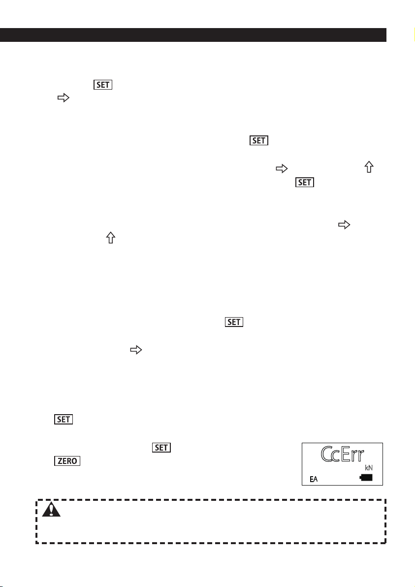
入力数値がNGであれば表示部に「CcErr」および画面左下
に「EA」が表示されます。を押し再度やり直してください。
10
. を押し設定が終了し、測定状態に戻ります。
5
CcErr
kN
EA
ご注意 ここでの設定を間違えますと正しく測定できませんのでご注意ください。
一度設定しますと電源をOFFにしても設定は消去されませんので、測定
器をかえずにご使用いただく際には、再度設定する必要はありません。
3.表示器の設定方法
6
3-3ロ−パワ−[F-5]
3-4コントラスト[F-14]
ローパワーモードには,オートパワーオフ,バックライトオフがあり,消費電流を低減して乾
電池の消耗を抑えることができます。
◆オートパワーオフ
電源スイッチの切り忘れによる乾電池の消耗を防ぐ機能です。最終操作から自動で電源が切
れる時間を設定します。設定時間は,0〜99分です。
◆バックライトオフ
バックライトの切り忘れによる乾電池の消耗を防ぐ機能です。バックライトの点灯から自動
で消灯する時間を設定します。設定範囲は,0〜99秒です。
オートパワーオフ,バックライトオフ機能を使用しない場合は,設定時間を「00」に設
定して下さい。
《操作方法》
1.電源スイッチを【MEAS】側に動かして放します。
2.測定状態で を3秒以上押し続けると設定モードに入り、[F-1]が表示されます。
3.を押すと[F-1][F-2][F-3][F-4][F-5][F-7][F-10][F-11][F-12][F-13]
[F-14][F-15]の設定内容が順次表示されます。
4.[F-5ローパワー]を表示し を押します。
5.[
F-5
]
およびパワーオフの数値が点滅します。 または を押し00〜99分(MIN)の範囲内
で設定します。
6.を押し、バックライトの設定に移ります。
7.[
F-5
]
およびバックライトの数値が点滅します。 または を押し00〜99秒(SEC)の範囲
内で設定します。 を押すと
[
F-5
]
の点滅が終了します。
8.を押し、設定が終了し測定状態に戻ります。
《操作方法》
1.電源スイッチを【MEAS】側に動かして放します。
2.測定状態で を3秒以上押し続けると設定モードに入り、[F-1]が表示されます。
3.を押すと[F-1][F-2][F-3][F-4][F-5][F-7][F-10][F-11][F-12][F-13]
[F-14][F-15]の設定内容が順次表示されます。
4.[F-14コントラスト]を表示し を押します。
5.[F-14]およびコントラストの数値が点滅します。 を押し00〜30の範囲内で設定します。
を押すと[F-14]の点滅が終了します。
6. を押し、設定が終了し測定状態に戻ります。
画面のコントラストを変更することができます。

7
4.補足説明
4-1設定モード変更方法
4-2設定モード一覧
[F-1]:ひずみ単位設定
測定器の内部センサーから出力されるひずみ信号に対し、表示器の感度校正を行う際に、
ひずみ値と電圧値のどちらを用いるのかを選定するモードです。ダイナフォースではより
信頼性の高いひずみ値で設定を行います。お客様での[F-1]設定は不要です。万一、設定を
変更してしまった際には、『4-1 設定モード変更方法』を参照に初期値単位に戻してくだ
さい。
初期値⇒με
[F-2]:実負荷校正登録
荷重を加えて校正登録します。[F-2]は使用しません。万一、誤操作した場合は、
『3-2感度校正登録[F-3]』で設定し直してください。
[F-3]:感度校正登録
表示器に測定器の感度校正値を登録します。また、表示桁数の変更を行います。
『3-2感度校正登録[F-3]』を参照に登録を行ってください。
[F-4]:弊社で設定しておりますので、ご使用にならないでください。
万一、設定を変更してしまった際には、『4-1設定モード変更方法』を参照に初期値に戻
してください。
初期値⇒ヘイキン:16、メモリ:1、ゼロフキン:0
[F-5]:ロ−パワ−
電源およびバックライトの切り忘れを防止する機能です。「0」の場合は,機能しません。
『3-3ローパワー[F-5]』を参照に設定を行ってください。
初期値⇒パワーオフ:0MIN、バックライト:10SEC
1.測定状態で を3秒以上押し続けると設定モードに入り、[F-1]が表示されます。
2.を押すと[F-1][F-2][F-3][F-4][F-5][F-7][F-10][F-11][F-12][F-13]
[F-14][F-15]の設定内容が順次表示されます。
3.設定内容を変更するモード画面を表示させ を押すと[F-**]が点滅します。
4. または を押し設定内容を変更してください。
5.設定内容変更後 を押すと設定が完了し「F-**」の点滅が終了します。
6. を押し、設定が終了し測定状態に戻ります。
[F-7]:弊社での調整用ですので、ご使用にならないでください。
万一、設定を変更してしまった際には、『4-1設定モード変更方法』を参照に初期値に戻
してください。
初期値⇒自動読込:シナイ、自動ゼロ:シナイ、定格出力:スル、定格容量:スル
単位:スル

8
[F-13]:ゲンゴ
設定モードの表記文字を日本語(カタカナ)または英語にすることができます。
ニホンゴ⇔ENGLISH 『4-1設定モード変更方法』を参照に設定を行ってください。
初期値⇒ニホンゴ
[F-14]:コントラスト
画面のコントラストを変更することができます。
『3-4コントラスト[F-14]』を参照に設定を行ってください。
初期値⇒11
[F-11]:弊社での調整用ですので、ご使用にならないでください。
初期値⇒TEDSカンドトウロク
[F-12]:弊社で設定しておりますので、ご使用にならないでください。
万一、設定を変更してしまった際には、『4-1設定モード変更方法』を参照に初期値に戻
してください。
初期値⇒チカラ kN
・キーロック:キーロック機能が「スル」の場合は,電源が投入される度に,キー
ロック状態で起動し, (鍵マーク)が表示されます。
・ロックキー: がロックされ、 は使用できます。
・キーロックの解除: と キーを同時に長押し(約3秒)します。
(鍵マーク)が消えて,ロックが解除されます。
[F-15]:キーロック
「スル」に設定した場合は,電源の投入時は必ずキーロック状態で立上ります。
シナイ⇔スル 『4-1設定モード変更方法』を参照に設定を行ってください。
[F-10]:弊社での調整用ですので、ご使用にならないでください。
万一、設定を変更してしまった際には、『4-1設定モード変更方法』を参照に初期値に戻
してください。
4-3エラー表示
エラーが表示された場合は,再度設定を行うか電源の再投入を行って下さい。
oL/−oL表示:表示値オーバー
Ad/−Ad表示:測定範囲オーバー
CcErr/EA表示:校正値設定異常
4-4バッテリ−電圧低下表示
ローバッテリー 点滅表示の場合は使用を中止し、新しいバッテリ−に交換してください。
電池マーク表示: (1/1)、 (1/2)、 (1/4)の点灯、 の点滅
ローバッテリー 点滅時は、 の操作は出来ません。
4.補足説明
9
5. 使用上のご注意
●測定する機械によっては、プルボルトの微小な長さの違いによって、測定値に変化が生じる場合
があります。定期検査において引張力の変化をより安定して測定を行いたい場合は、測定用のプ
ルボルトを決めて同じ物をご使用ください。
●プルボルトを強く締めますと、測定素子に余計な負荷がかかってしまいますので、プルボルトは
手で締める程度にしてください。
●本機はATCできません。機械主軸に取り付ける際に、指などを挟んだりしないよう注意してくだ
さい。
●機械主軸は絶対に回転させないでください。
●防水構造ではありませんので測定器、表示器への浸水にはご注意ください。
●測定器:温度補償範囲0℃〜60℃ 防水性防滴程度
表示器:使用温度範囲−5℃〜40℃ 使用湿度範囲20〜85%RH(結露しないこと)
以上の範囲を超えての使用はしないでください。
●ご使用後には必ず電源をOFFにしてください。
●電池交換は、単三乾電池2本を同時に新品と交換してください。
●本機は精密機器です。取扱いには十二分にご注意していただき、落としたり衝撃を与えたりしな
いでください。また、ご使用後は錆を防ぐために丁寧に拭き、必ず防錆処理を行ってから専用
ケースに入れ、保管してください。
●本機は精密機器のため、お客様での分解・改造は行わないでください。性能等を劣化させる原因
にもなり保証できなくなります。
●長期間ご使用にならない場合は、電池を取り外してください。
●
不具合が発生した場合はご使用を中止し、ご購入先を通じて弊社へ修理、点検にお出しください。
ダイナフォースは測定器です。精度維持および末永くご使用いただくために、定期的に検査・校正
を行ってください。(使用頻度にもよりますが、1回/年程度を目安に実施してください。)
またBIGでは、校正証明書・トレーサビリティー体系図の発行を有償で行っています。
ご購入先を通じて、弊社へご依頼ください。

10
1. Specifications
1-1 Descriptions
●Measuring device ●Exclusive case
●Display unit
●Accessory cable
Connector
Jack to be connected through an accessory cable to the measuring device.
Power supply
Push the button to switch the power and backlight ON/OFF.
SET button
To be used as a decision button at the time of set up only.
ZERO/ button
To be used during set up such as entering values and for zero reset during measurement.
(Displays "ZERO" on the LCD.)
HOLD/ button
To be used for changing the number of digits, moving the decimal point or selecting peak hold mode during set up.
Battery box
2 pcs. of AA alkaline or manganese batteries are used exclusively.
LCD
Displays the measured value and status.
1
1
2
3
4
5
6
7
CAUTION
Do not use the [STRAIN] mode, as it is for error diagnosis by the manufacturer.
Pocket
for cable
Display side
(large)
Measuring device
side (small)
POWER
STRAIN
MEAS
POWER
STRAIN
MEAS
Ser.No.
12
5
7
3
4
TYPE : DFA-1
6

11
2. How to measure
CAUTION
For the display unit purchased as a part of the Dyna Force set, set up procedure is already completed on delivery.
For the display unit purchased alone or to be used as a replacement, set up of the display unit is
required, as rated capacity and output vary depending on measuring unit. Refer to "3. How to set up
display unit" and follow the instructions. Neglecting to do so may lead to incorrect measurement.
Install a pullstud suitable for the machine to measure in the measuring device.
For machining centers with MAS or JIS standard spindles, your existing pullstud can be used.
However, for other standards such as DIN, ISO, CAT or ANSI, the pullstud exclusively designed for
Dyna Force is required.
Connect the measuring device to the display unit through an
exclusive cable. Ensure power of the display unit is turned off.
2-1 Installation of pullstud
2-2 Connection between measuring device and display unit
2-3 Power activation
2-4 Zero reset
CAUTION ●Do not use【STRAIN】mode, as it is for error diagnosis by manufacturer.
If operated in【STRAIN】mode, resetting is required as indicated in
"3. How to set up display unit".
●
If the battery symbol is blinking, the battery charge is low. Replace the battery.
Measured values may vary due to slight difference in length of each
pullstud. If more stable measurement is required, always use the same
piece of pullstud.
If a pullstud is tightened too much, excessive load is applied to the
measuring element. Hand-tightened installation is recommended.
●
●
Display side (large)
Measuring device
side (small)
CAUTION ●Be sure to connect the measuring
unit through an exclusive cable
before turning on the display unit.
• Push the 【POWER】switch to turn on the power.
POWER
STRAIN
MEAS
POWER
STRAIN
MEAS
• The start-up screen is displayed for about 2 seconds,
then shifts to the measurement screen.
•
Push the【POWER】switch again to turn on the backlight. Push the【POWER】switch again to turn off the backlight.
• Slide the power switch to the 【MEAS】position and release it.
CAUTION
0.0
kN
ZERO
Push
ZERO
.
"ZERO" is displayed on the LCD and the displayed value changes to "0".
●Make sure that "ZERO" is displayed on the LCD,
and proceed to the next page.
12
Install the measuring device in the machine spindle manually. Measured drawing force is indicated on
the display unit. Unit is kN. (10kN = 1,020kgf)
"oL/-oL" or "Ad/-Ad" indication represents input overshoot. Refer to the Table 1 shown below and make a
measurement once again. If you still have trouble, contact our agent.
2-5 Installation to machine spindle
2-6 Peak-hold measurement
2-7 End of measurement
2-8 Replacement of batteries
●Subsequent measurement by using the same measuring device
●Subsequent measurement by using another measuring device
Table 1 Factors and solutions of input overshoot
Factor Solution
Replace the pullstud with a correct one.
Clean tapers.
Refer to "3-2 Sensitivity calibration entry [F-3]" and configure the setting.
Select【MEAS】mode.
Wrong pullstud
Dirt stuck between tapers
Error in sensitivity calibration
Measured in STRAIN mode
Max. measured value is maintained and displayed.
1. After zero resetting, push HOLD .
"HOLD" is displayed on the LCD to show that peak hold measurement is in progress.
2. Install the measuring device in the machine spindle and make a measurement. By pushing
HOLD again, peak hold mode is ended and the current input value is indicated.
To turn off the power, push and hold the【POWER】 switch.
Open the battery box by sliding the cover.
2 pcs. of AA alkaline or manganese batteries are used exclusively.
No set up is required, as all the previous set up are not erased even if the power is turned
off or batteries are replaced.
Sensitivity calibration entry is required for both the rated capacity and output, as they vary
depending on the measuring device. Refer to "3-2 Sensitivity calibration entry [F-3]" and
configure the setting.
CAUTION Clean tapers of both machine spindle and measuring device before
installation.
Care should be taken not to get a finger caught in the spindle when
installing the measuring device.
●
●

13
3. How to set up display unit
CAUTION
If wrong values are indicated, perform "3-2 Sensitivity calibration entry [F-3]".
Operating precautions
To prevent incorrect operation, buttons are designed to respond to slow and secure push only.
For the display unit purchased as a part of the Dyna Force set, set up procedure is already
completed on delivery. Therefore, set up is not required unless the original pair is changed.
For the display unit purchased alone or to be used as a replacement, set up of the display unit is
required, as rated capacity and output vary depending on measuring unit. Follow the instructions
shown on the next page for the set up. Neglecting to do so may lead to incorrect measurement.
Unit of displayed values is kN. (eg.: 10kN = 1020kgf)
《Operation procedure》
1. Slide the power switch to the【MEAS】position and release it.
2. While in measurement mode, push SET for 3 seconds or longer. The display unit enters set up
mode and [F-1] is indicated.
Display language on delivery is Japanese. For English, refer to page 8 "[F-13]: Language" and
change the setting.
3. Push , and the setting contents of [F-1], [F-2], [F-3], [F-4], [F-5], [F-7], [F-10], [F-11], [F-12],
[F-13], [F-14] and [F-15] are indicated in sequence.
4. Values of the rated output (RO) and rated capacity (RC) indicated on the inspection sheet and
nameplate of the measuring device appear on the [F-3 ENROLMNT ADJ] display.
5. Ensure the correct values are displayed, and push ZERO to return to measurement mode.
3-2 Sensitivity calibration entry [F-3]
3-1 Confirming sensitivity calibration
*Example Inspection sheet
MAX.30kN
Rated output 3292
Nameplate
Rated capacity (RC)
Rated output (RO)
• Rated capacity (RC): 30kN
• Rated output (RO): 3292με

14
《Operating procedure》
1. Slide the power switch to the【MEAS】position and release it.
2. While in measurement mode, push SET for 3 seconds or longer. The display unit enters set up
mode and [F-1] is indicated.
3. Push , and the setting contents of [F-1], [F-2], [F-3], [F-4], [F-5], [F-7], [F-10], [F-11], [F-12],
[F-13], [F-14] and [F-15] are indicated in sequence.
4. Values of the rated output (RO) and rated capacity (RC) indicated on the inspection sheet and
nameplate of the measuring device appear on the [F-3 ENROLMNT ADJ] display. Push SET
while confirming these are indicated.
5. [F-3] and the rated output (RO) will blink.
Enter the rated output (RO) indicated on the inspection sheet and nameplate.
Push and select the digit to enter. Change the value by pushing . Ensure the correct rated
output (RO) value is displayed, and push SET .
This completes the set up of the rated output (RO). Start set up of the rated capacity (RC) with
the following procedure.
6. [F-3] and the rated capacity (RC) will blink.
7. Enter the rated capacity (RC) (max.〇〇kN) indicated on the inspection sheet and nameplate.
Push and select the digit to enter. Change the value by pushing . The number of digits to
be displayed during measurement should be considered.
Example: Measuring unit with 30kN rated capacity
To display without decimals →Enter [+00030]
To display to the 1st decimal place →Enter [+00300]
To display to the 2nd decimal place →Enter [+03000]
Ignore the decimal point when entering.
Ensure the correct rated capacity (RC) value is displayed, and push SET . This completes the
set up of the rated capacity (RC). Start set up of the decimal point with the following procedure.
8. After the decimal point blinks, push and move the decimal point to the desired position.
Be sure to set to the decimal point position determined in the previous step.
Example Enter [+00030] →[+00030.] without decimal places
Enter [+00300] →[+0030.0]
Enter [+03000] →[+030.00]
9. Push SET and complete the position of the decimal point. If completed
correctly, [F-3] stops blinking.
If the input value is wrong, "CcErr" is displayed and "EA" appears at the
bottom left of the LCD. Push
SET
and go through the process again.
10.
Push ZERO to complete the setting and return to the measurement mode.
EA
CAUTION
If there is an error in these set ups, correct measurement is not achieved.
All the previous set ups are not erased even when the power is turned off.
Therefore, resetting is not required unless another measuring device is used.
CcErr
kN
3. How to set up display unit
15
3-3 Low power [F-5]
3-4 Contrast [F-14]
The low power mode enables auto power-off and backlight off, which can reduce the power
consumption of the battery.
◆Auto power-off
This function prevents battery consumption due to leaving the power switch on. It sets the
time until auto power-off after the final operation. The setting time is 0 to 99 minutes.
◆Backlight off
This function prevents battery consumption due to leaving the backlight on. This sets the time
until auto backlight off after it is turned on. The setting range is 0 to 99 seconds.
When not using the auto power-off and backlight off functions, set the time to "00".
《Operating procedure》
1. Slide the power switch to the【MEAS】position and release it.
2. While in measurement mode, push SET for 3 seconds or longer. The display unit enters set up
mode and [F-1] is indicated.
3. Push , and the setting contents of [F-1], [F-2], [F-3], [F-4], [F-5], [F-7], [F-10], [F-11], [F-12],
[F-13], [F-14] and [F-15] are indicated in sequence.
4. Select [F-5 LOW POWER] and push SET .
5. [F-5] and the power-off value will blink. Push or to set the time in a range of 00 to 99
minutes (MIN).
6. Push SET to move on to backlight setting.
7. [F-5] and the backlight value will blink. Push or to set the time in a range of 00 to 99
seconds (SEC). Push SET and [F-5] stops blinking.
8. Push ZERO to complete the setting and return to the measurement mode.
《Operating procedure》
1. Slide the power switch to the【MEAS】position and release it.
2. While in measurement mode, push SET for 3 seconds or longer. The display unit enters set up
mode and [F-1] is indicated.
3. Push , and the setting contents of [F-1], [F-2], [F-3], [F-4], [F-5], [F-7], [F-10], [F-11], [F-12],
[F-13], [F-14] and [F-15] are indicated in sequence.
4. Select [F-14 CONTRAST] and push SET .
5. [F-14] and the contrast value will blink. Push to set in a range of 00 to 30. Push SET and [F-14]
stops blinking.
6. Push ZERO to complete the setting and return to the measurement mode.
The contrast of the screen can be changed.

16
4. Supplementary explanation
4-1 Changing the setting mode
4-2 Setting mode list
[F-1]: Distortion unit setting mode
Functions to select either distortion value or voltage value when calibrating sensitivity of the
display unit against distortion signal output from the inner sensor of the measuring device.
Dyna Force utilizes distortion value, which is more accurate. [F-1] set up by customers is not
required. In case the set up is changed, refer to "4-1 Changing the setting mode" and return
to the initial value.
Initial value ⇒με
[F-2]: Actual load calibration mode
For calibration with load. This [F-2] should not be used. If misoperation takes place, refer to
"3-2 Sensitivity calibration entry [F-3]" for resetting.
[F-3]: Sensitivity calibration entry mode
For entering sensitivity calibration values into the measuring device. Also for changing display digits.
Register in accordance with "3-2 Sensitivity calibration entry [F-3]".
[F-4]: For manufacturer's use only.
In case the set up is changed, refer to "4-1 Changing the setting mode" and return to the
initial value.
Initial value ⇒AVERAGE : 16, MIN-VAL : 1, NEAR-ZR : 0
[F-5]: Low power
This function prevents accidentally leaving the power or backlight on. If it is set to "0", it will not
function. Set according to "3-3 Low power [F-5]".
Initial value ⇒PWR OFF : 0 MIN, BKL OFF : 10 SEC
1. While in measurement mode, push SET for 3 seconds or longer. The display unit enters set
up mode and [F-1] is indicated.
2. Push , and setting contents of [F-1], [F-2], [F-3], [F-4], [F-5], [F-7], [F-10], [F-11], [F-12],
[F-13], [F-14] and [F-15] are indicated in sequence.
3. After the mode to change is displayed, push SET and [F-**] starts blinking.
4. Push or to change the settings.
5. After the settings are changed, push SET to complete the set up and [F-**] stops blinking.
6. Push ZERO to complete the setting and return to the measurement mode.
[F-7]: For manufacturer's use only.
In case the set up is changed, refer to "4-1 Changing the setting mode" and return to the
initial value.
Initial value ⇒PWR-ON READ : DIS, ZERO AT READ : DIS, RATED OUT PUT : ENA,
RATED CAPCTY : ENA, UNIT : ENA

17
Battery mark display: (1/1), (1/2), (1/4) lit, blinking
If the low battery blinks, discontinue use and replace the battery.
When the low battery is blinking, ZERO and SET operations are not available.
[F-13]: Language
The display language in setting mode can be set to Japanese (katakana) or English.
ニホンゴ ⇔ENGLISH Change the setting according to "4-1 Changing the setting mode".
Initial value ⇒ニホンゴ
[F-14]: Contrast
The contrast of the screen can be changed.
Set according to "3-4 Contrast [F-14]".
Initial value ⇒11
[F-11]: For manufacturer's use only.
Initial value ⇒ENROL BY TEDS
[F-12]: For manufacturer's use only.
In case the set up is changed, refer to "4-1 Changing the setting mode" and return to the
initial value.
Initial value ⇒FORCE kN
• Key lock:
If the key lock function is set to "ON", it will always start up with the key lock ON
when the power is turned on, and (key mark) will be displayed.
• Lock key: Locks SET , allowing use of
ZERO
and
HOLD .
•
Releasing key lock: Push and hold
HOLD
and
SET
simultaneously (about 3 seconds).
(key mark) disappears and the lock is released.
[F-15]: Key lock
When set to [ON], it will always start up with the key lock ON when the power is turned on.
OFF ⇔ON Change the setting according to "4-1 Changing the setting mode".
[F-10]: For manufacturer's use only.
In case the set up is changed, refer to "4-1 Changing the setting mode" and return to the
initial value.
4-3 Error display
If an error is displayed, do the set up again or turn the power OFF/ON again.
oL/-oL display: Displayed value overshoot
Ad/-Ad display: Measuring capacity overshoot
CcErr/EA display: Calibration value setting error
4-4 Battery voltage drop display

18
●Measured values may vary due to slight difference in length of each pullstud. If more stable
measurement is required, always use the same piece of pullstud.
●If a pullstud is tightened too much, excessive load is applied to the measuring element.
Hand-tightened installation is recommended.
●
Dyna Force is not capable of automatic tool change. Care should be taken not to get your finger caught
in the spindle when installing the measuring device.
●Never rotate the machine spindle.
●Keep the measuring device and display unit dry, as they are not water resistant.
●Measuring device: Temperature compensation range: 0°C to 60°C
Waterproof performance: Not more than drip-proof
Display unit: Operating temperature: -5°C to 40°C Operating humidity: 20 to 85%RH
(Condensation should be avoided.)
Never exceed the above ranges.
●Be sure to turn off power after use.
●Replace both (2) AA batteries at the same time.
●Dyna Force is a precision instrument. Handle carefully and avoid any drop and excessive impact.
Clean, provide rustproof treatment and store the equipment in the exclusive case after use.
●Never disassemble Dyna Force devices, as they are precision instruments. Warranty is void
and performance is worsened once disassembled.
●Remove batteries when stored for an extended period.
●Stop use and consult with our agent for inspection or repair in case of any failure.
Dyna Force is a measuring instrument. Periodic inspection and calibration are required.
(Once a year as a guide, though it depends on frequency of use.)
Calibration certificate and traceability chart are available at cost. Contact our agent.
5. CAUTIONS
Table of contents


