Tense TPM-02 User manual
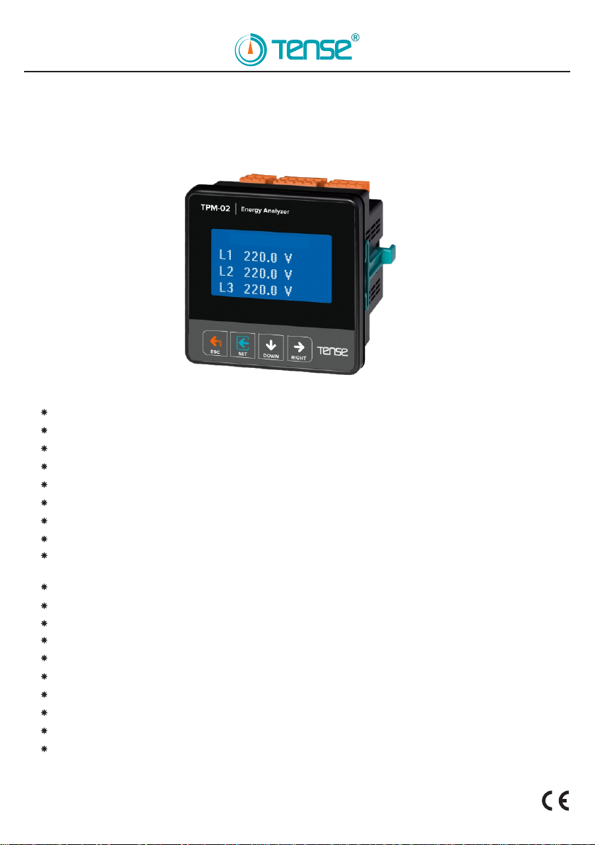
TPM-02
Tense Elektric Electronic Industry
ENERGY ANALYZER
Document Number: DK030-3
EASY TO USE
It shows voltage (V) minimum (min), maximum (max) and mean values of phase-to-neutral and
phase-to-phase.
It measures up to 31rd voltage and current harmonics.
RS485 Modbus RTU (1200-115200 bps)
128 x 64 Graphic LCD
3-phase voltage and 3-phase current transformer.
It shows per-phase and total active (P1, P2, PΣ) powers.
It shows per-phase and total apparent (S, S2,S3,SΣ) powers.
It shows per-phase and total reactive (Q, Q2,Q3,QΣ inductive and capacitive) powers.
It shows power factors ( PF) and Cosφ values of each phase.
It shows total current value (I1, I2,I3,IΣ) of each phase.
It shows total imported active energy (ΣkWh) value.
It shows total exported active energy (ΣkWh) value.
It shows total inductive reactive energy (ΣkVArh) value.
It shows total capacitive reactive energy value (ΣkVArh).
It shows demands.
You can delete the energies and demands.
Date and time is adjustable.
Real time clock
Menu is password-protected.
MADE IN TURKEY
Voltage L-N
2/6
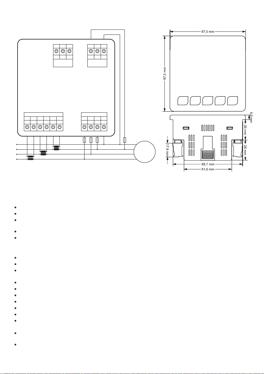
1 - Connection Diagrams and Dimensions:
2 - Points to Take into Consideration in the Selection and Connection of Current Transformer:
In order to prevent any mistake while connecting the output terminals of the current transformer, use cables in different
colors for each phase or designate a number for each cable.
Keep the cables connected to the output terminals of the current transformer away from the high-voltage line.
In order to prevent any shake on the current transformer, fix it on the bus-bar, cable or rail.
Be sure that the current transformer value is higher than the maximum current drawn from the system.
It is recommended to use a current transformer in class (can be specified as class, cl, kl) 0,5.
3 - Warnings
Do not expose the LCD display directly to sunlight in order to avoid any harm on it.
Note that the temperature level on the panel to which the device is mounted is at the range of operating temperature of
the device (-20ºC – 55ºC).
There must be a space of 5cm behind the device after its installation.
Fix the device securely to the front-cover of the panel with the apparatus delivered together with the device.
Use the device according to the instructions specified by us.
Be sure that the panel to which the device is mounted does not operate in a humid environment.
Place the switch or circuit breaker close to the device or in a location which is easily accessible for the operator.
Place a switch or circuit breaker on the system during installation of the device.
Please note that the cables must not be energized during installation.
Flexible monitored and twisted cables must be used for the input and output lines which are not connected to the mains.
These cables must be kept away from lines and devices carrying high voltage.
Installation of the device and electrical connections must be performed by the technical personnel according with the
instructions specified in the user's manual.
The feeder cables must be compatible with the requirements of IEC 60227 or IEC 60245
3P4W connection type. 3 phase current and3 phase voltage and
with neutral.
N
L1
L2
L3
Load
CT1
P1
S1
P2
S2
CT2
P1
S1
P2
S2
CT3
P1
S1
P2
S2
B GNDA
RS485
A1
A2
85-240VAC
50/60Hz. <6VA
k3 k2 k1
C.T. Connections
l3 l2 l1 N
Voltage Inputs
L1
L2
L3
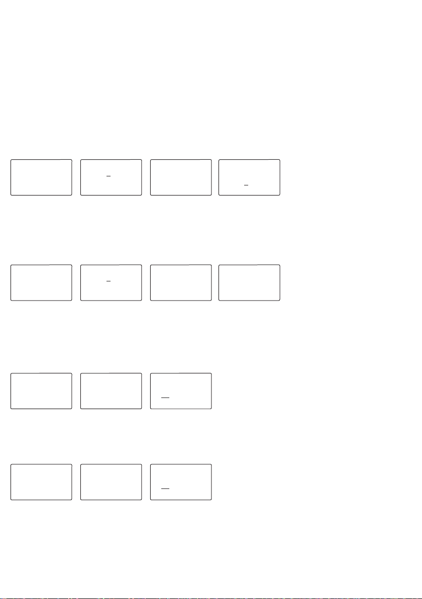
Figure-9 Figure-12 Figure-13
Figure-9 Figure-10 Figure-11
3/6
Press DOWN button when figure-4 is being displayed. Press set button if you did not create a new password. Figure-6 will be
displayed. When you press set button again, figure-7 is displayed. Press DOWN button to select the digit you want to change.
Press the UP button to enter the value of the digit with under-line. When you press the set button after you enter the rate, the
current transformer value is saved and the figure-6 is displayed. You can exit the settings menu by using Esc button.
For example: 100/5A current transformer ratio (multiplier value) is 20. CTR value is required to be set as 0020.
Press DOWN button when figure-4 is being displayed. Press set button if you did not create a new password. Figure-6 will be
displayed. When you press down button, figure-8 is displayed. When you press set button, figure-9 is displayed. Press DOWN button
to select the digit you want to change. Press the UP button to enter the value of the digit with under-line. When you press the set
button after you enter the rate, the voltage transformer value is saved and the figure-8 is displayed. You can exit the settings menu
by using Esc button.
Figure-4 Figure-5 Figure-8 Figure-9
Figure-4 Figure-5 Figure-6 Figure-7
Read the warnings before the device is energized. Make sure that the device is connected according to the connection
diagram. When the device energized for the first time, the figure-2 is displayed. Enter the current transformer ratio and the
voltage transformer ratios, if installed, on the settings menu at first.
6 - Start-up of the Device:
5 - General
TPM-03 energy analyzer measures the load on the system and voltage, current, Cosφ, active power, reactive power minimum
and maximum values, demands and energies related to this load on the system and saves the cases. It measures the current
and voltage harmonics to the 31rd harmonic.
4 - Maintenance of the Device
De-energize and disconnect the device. Clean the body of the device with a dry or damp-dry cloth. Do not use conductive or
other chemical substances as a cleaning agent that can damage the device. After cleaning the device, make its connections and
check whether it is working by energizing it.
7 - Changing Current Transformer Ratio
8 - Changing Voltage Transformer Value
Settings Pass: 0000 Current Trans.
Ratio
Max Value 5000
CTR: 0001
Max Value 4000.0
VTR: 0001.0
Voltage Trans.
Ratio
Pass: 0000
Settings
10 - Setting the Time
9 - Setting Date
Date Set
Date & Time
01/01/2014
15:51:13 01/01/2014
New Date
01:01:20
New TimeTime Set
Date & Time
01/01/2014
15:51:13
Press DOWN button when figure-9 is being displayed.
Figure-10 will be displayed. When you press set button,
figure-11 is displayed. The sequence of date is day/month/
year. The line is firstly under the digit of day. Press the UP
button to change the day. Press DOWN button and see the line
is under the digit of month to change month. Enter the month
by pressing UP button. Press DOWN button and see the line is under the digit of year to change year. Enter the year by pressing UP
button. Then, when you press set button, the date is saved and the figure-10 is displayed. You can exit the settings menu by using
Esc button.
Press DOWN button when figure-9 is being displayed.
Figure-10 will be displayed. Figure-12 is displayed when you
press the DOWN button again. When you press set button,
figure-13 is displayed. The sequence of the time is hour:minute:
second. The line is firstly under the digit of hour. Press the UP
button to change the hour. Press DOWN button and see the line
is under the digit of minute to change minute. Enter the minute
by pressing UP button. Press DOWN button and see the line is under the digit of second to change second. Enter the second by
pressing UP button. Then, when you press set button, the time is saved and the figure-12 is displayed. You can exit the settings
menu by using Esc button.

Settings Pass: 0000 Password Set New Pass
Pass: 0000
4/6
Figure-4
Figure-4
Figure-4
Figure- 5
Figure-5
Figure-5
Figure-14
Figure-16
Figure-18
Figure-15
Figure-17
Figure-19
Press DOWN button when figure-4 is being displayed. Press set button if you did not create a new password. Figure-6 will be
displayed. When you press DOWN button, figure-8 is displayed. Figure-14 is displayed when you press DOWN button again.
Figure-16 is displayed when you press DOWN button again. Figure-18 is displayed when you press DOWN button again. When
you press set button, figure -19 is displayed. By pressing DOWN button you can select different digits and you can adjust the
digit values by pressing UP button. If you press SET button after you enter the password, the password is changed and the
figure-18 is displayed. You can exit the settings menu by using Esc button.
BAUD: 9600 *
PRTY: Yok
STOP: 1
MBID: 1
MODBUS RS485
Pass: 0000
Settings
11 - RS485 Remote Communication Settings:
Del No Del
Energy ( ) (x) *
Demand ( ) (x)
ENERGY/DEMAND
Pass: 0000
Settings
12 - Deleting the Energy and Demands
13 - Entering the Password Value
Press DOWN button when figure-4 is being displayed. Press set button if you did not create a new password. Figure-6 will be
displayed. When you press DOWN button, figure-8 is displayed. Figure-14 is displayed when you press DOWN button again.
Figure-16 is displayed when you press DOWN button again. When you press set button, figure -17 is displayed. If you want to
reset the energy values, see the sign (*) is on the energy value and press the UP button, see the sign (x) is on delete option.
Then, press DOWN button to bring the sign (*) on demand value. If you also want to reset the demand value, bring the sign (x)
on delete option by using up button and then press the set button. When you press the set button, energy and demand values
are reset and the figure-16 is displayed. You can exit the settings menu by using Esc button.
Press DOWN button when figure-4 is being displayed. Press set button if you did not create a new password. Figure-6 will be
displayed. When you press DOWN button, figure-8 is displayed. Figure-14 is displayed when you press DOWN button again. When
you press set button, figure -15 is displayed. The values herein baud:9600, party: no and stop bit: 1 are adjusted in conformity
with the tense products. Put the sign (*) near the relevant value by using DOWN button to change any value . You can change the
value by pressing UP button. When a modem is connected with more than one communication device, the serial number or
Modbus address should be different. In such cases, enter a value different from that of other devices. If you press set button
when the sign(*) is on MBID value, the change is saved and the figure-14 is displayed. You can exit the settings menu by using
Esc button.
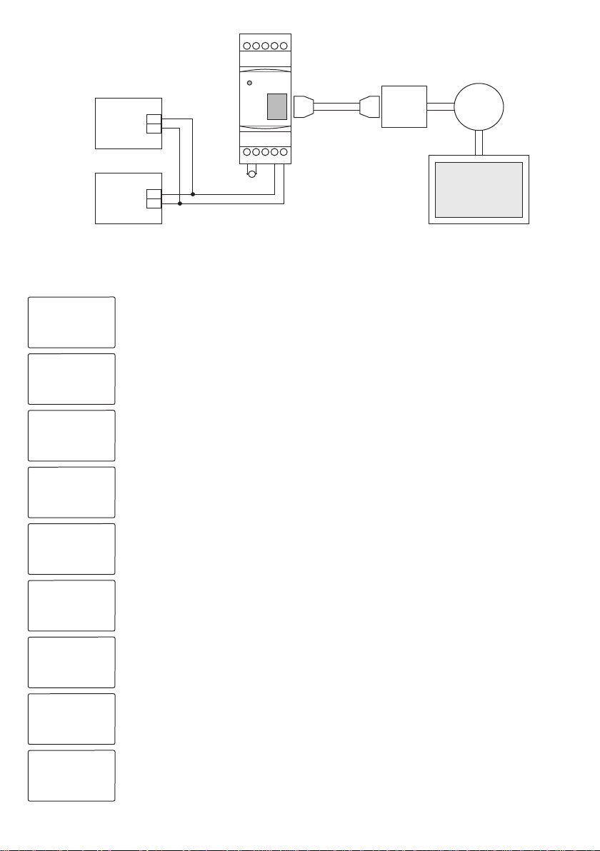
14 - Remote Communication with GSM-MOD
Figure-22
Energy
analyzer
(TPM-02/03)
Counter /
Reactive
Relay
PC - Computer
Operator Internet
/ Server
A1 A2
220V
AC
AB 5V
GND
TX RX
GSM-MOD
~
RS485
RS485
B
B
A
A
Counter
RS232
RX
GND
TX
Only the energy analyzer or the counter and reactive relay together with it can be connected for remote communication with
GSM-MODE. Remote communication is provided through energy analyzer (counter and reactive relay) on www.tenseenerji.com
(server) by using 100MB (recommended) data line from GSM operators.
5/6
16 - Display Information
Figure-24: It shows phase-neutral voltage values. You can see the minimum, maximum and mean
voltage values by pressing DOWN button. Press the UP button to navigate on the display.
Figure-25: It shows phase-phase voltage values. You can see the minimum, maximum and mean
voltage values by pressing DOWN button. Press the UP button to navigate on the display.
Figure-26: It shows current value of each phase and total current values. You can see the minimum,
maximum and mean current values and demands by pressing DOWN button. Press the UP button to
proceed on the display.
Figure-27: It shows (P) active power and total active power values of each phase. You can see the
minimum, maximum and mean active power values and demands by pressing DOWN button. Press the
UP button to navigate on the display.
Figure-28: It shows (Q) reactive power and total reactive power values of each phase. The values with (-)
show capacitive reactive power values and those without (-) show the inductive reactive power. You can
see the minimum, maximum and mean reactive power values and demands by pressing DOWN button.
Press the UP button to navigate on the display.
Figure-29: It shows the (S) apparent power and total apparent power values of each phase. You can see
the maximum, mean apparent power values and demands by pressing DOWN button. Press the UP button
to navigate on the display.
Figure-30: It shows (PF) power factor and total power factor values of each phase. You can see the
Cosφ values by pressing DOWN button. Press the UP button to navigate on the display.
Figure-31: It shows (THDV) total harmonic distortion voltage percentages of each phase. You can see
the voltage and current percentages of the 31st harmonic of each phase, (THDI) total harmonic distortion
percentages of currents by pressing DOWN button. Press the UP button to navigate on the display.
Figure-32: It shows imported (+ΣkWh) active energy values and total imported active energy values of
each phase. You can see experted (+ΣkWh) active energy, inductive imported (+ΣkVarh) reactive energy
and capacitive (+ΣkVarh) reactive energy values by pressing DOWN button. Press the UP button to
navigate on the display.
Figure-24 Figure-25
Figure-26
Figure-28 Figure-27Figure-29 Figure-30Figure-31Figure-32
Only the energy analyzer or the reactive relay together with it can be connected for remote communication with ETH-MOD-T.
Remote communication is provided through energy analyzer or reactive relay on www.tenseenerji.com (server) by using a
modem connected to internet.
15 - Remote Communication with ETH-MOD-T
Modem Internet
/ Server
PC - Computer
220V
AC
~
Figure-23
Energy
Analyzer
Reactive
relay
RS485
RS485
B
B
A
A
ETH-MOD-T
Ethernet Cable
RJ-45
Connector RJ-45
Connector
A2A B
GND
A1
Voltage L-L
L12: 380.0 V
L23: 380.0 V
L31: 380.0 V
Voltage L-N
L1: 220.0 V
L2: 220.0 V
L3: 220.0 V
Active Im. kWh
L1: 1.000
L2: 1.000
L3: 1.000
T : 1.000
THDV %
L1: 0.00
L2: 0.00
L3: 0.00
Power Factor
L1: 1.000
L2: 1.000
L3: 1.000
T : 1.000
Apparent Pow
L1: 0.0 VA
L2: 0.0 VA
L3: 0.0 VA
T : 0.0 VA
Reactive Pow
L1: 0.0 Var
L2: 0.0 Var
L3: 0.0 Var
T : 0.0 Var
Current
L1: 0.000 A
L2: 0.000 A
L3: 0.000 A
T : 0.000 A
Active Pow
L1: 0.0 W
L2: 0.0 W
L3: 0.0 W
T : 0.0 W

85V - 300V AC
50 / 60 Hz
<6VA
-20ºC.....55ºC
5V -330V AC
5V - 600kV
5mA - 5,5A
5mA - 50.000A
%±0,5
%±0,5
%±0,5
%±1
%±1
%±1
%±1
3P4W
1....10000
1,0....4000
2 - 31
2 - 31
No
>5 years
Plug in Connection
2A / 250V AC (Resistive Load)
5V - 30V DC, <40mA DC
1.5mm²
Front-mounted to the panel
<2000meters
<300Gr.
IP40(Front panel), IP00(Body)
91mm x 91mm
Operating Frequency
Operating Power
Operating Temperature
Voltage input
Current input
Voltage Measurement Range
Current Measurement Range
Voltage Accuracy (L - L)
Voltage Accuracy (L - N)
Current Accuracy
THD-V Accuracy
Active Power Accuracy
THD-I Accuracy
Reactive Power Accuracy
Connection Type Supperted
Current Transformer Ratio
Voltage Transformer Ratio
Harmonic Voltage
Harmonic Current
Neutral Current Measurement
Real Time Clock
Connection Type
Contact Output
Pulse Output
Operating Voltage
Cable Diameter
Installation
Opretaing Altitude
Weight
Protection Class
Panel Hole Dimensions
RS485 MODBUS RTU
Communication
128 x 64 graphic lcd
Display
Imbalances (%)
VOLTAGE : 0.00
CURRENT : 0.00
Date & Time
01/01/2014
15:51:13
Frequency
L1: 50.0 Hz
L2: 50.0 Hz
L3: 50.0 Hz
Settings
Figure-33: It shows the frequency values of each phase. Press the UP button to proceed on the
display.
Figure-33
Figure -34: It shows the voltage and current irregularities in phases. Press the UP button to
navigate on the display.
Figure-35: It shows the date and time. You can set the date and time by pressing DOWN button.
Press the UP button to navigate on the display.
Figure-36: It enables you to enter the settings menu. It wants you enter the password value by
pressing the DOWN button. If you press the set button when the default password "0000" is written,
you enter the settings menu. You can delete the current transformer ratio, voltage transformer ratio,
energy and demand values, enter password value and change RS485 connection values on the
settings menu.
If you press set button as the figure-36 is being displayed, you can directly set the current
transformer ratio. If you press UP button as the figure-36 is being displayed, figure-24 will be seen
on the display. When you press the Esc button, always the figure-24 will be displayed.
Figure-34
Figure-35
Figure-36
17- Technical Specifications
18 - Table of Contents
1
2
2
2
3
3
3
3
3
3
3
4
4
4
4
5
5
6
6
6
Page
Subject:
Cover
15 - Remote Communication with ETH-MOD-T
17 - Technical Specifications
19 - Contact Information
18 - Table of Contents
13 - Entering the Password Value
14 - Remote Communication with GSM-MOD
1 - Connection Diagrams:
11 - RS485 Remote Communication Settings:
12 - Deleting the Energy and Demand.
7 - Changing Current Transformer Ratio
8 - Changing Voltage Transformer Value
3 - Warnings
5 - General
16 - Display Information
4 - Maintenance of the Device
10 - Setting the Time
9 - Setting the Date
2 - Points to Take into Consideration in the Selection and
Connection of Current Transformer
6 - Start-up of the Device:
Document Number: DK030-4
19 - Contact Informations: Energy and
Compensation
Tracking System
www.tenseenerji.com
6/6
Muratpaşa mah. Uluyol cad.
İşkent Sanayi Sitesi E-Blok 1.Kat
BAYRAMPAŞA / İSTANBUL / TÜRKİYE
Tel: 0212 578 04 38 - 48 | Fax: 0212 578 04 36
www.tense.com . t r i n f o@tens e . c o m .tr
|
Table of contents
Other Tense Measuring Instrument manuals


