Big Dutchman 307pro User manual
2016.10.01 • 612751-02
Software version 4.2
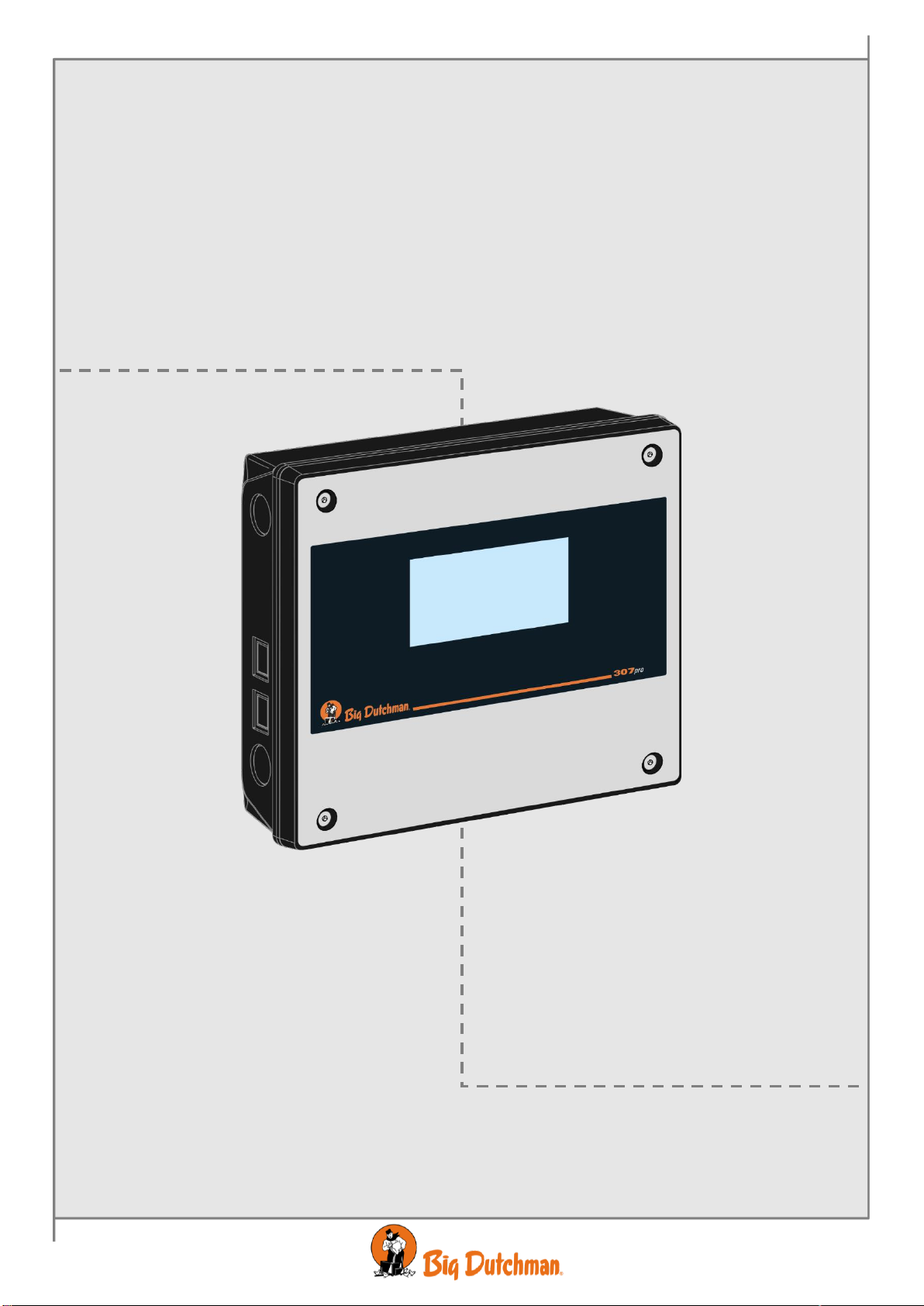
307pro Climate computer
Circuit Diagrams and Cable Plans
Code no. 99-97-3791 GB
Edition: 11/2016


307pro Climate computer
Program Version
The product described in this manual contains software. This manual corresponds to:
•Software version 4.2
•It was released in 2016.
Product and Documentation Changes
Big Dutchman reserve the right to change this manual and the product described herein without further
notice. In case of doubt, please contact Big Dutchman.
Latest date of change appears from the front and back page.
.
IMPORTANT
NOTES CONCERNING THE ALARM SYSTEM
Where climatic control is used in livestock buildings, breakdowns, malfunctions or faulty settings may
cause substantial damage and financial losses. It is therefore essential to install a separate, independent
alarm system, which monitors the house concurrently with the house computer. According to EU
directive 98/58/EEC, an alarm system must be installed in any house that is mechanically ventilated.
Please note that the product liability clause of Big Dutchman' general terms and conditions of sale and
delivery specifies that an alarm system must be installed.
In case of maloperation or improper use, ventilation systems can result in
production loss or cause loss of lives among animals. Big Dutchman recommend
that ventilation systems be mounted, operated and serviced only by trained staff and
that a separate emergency opening unit and an alarm system be installed as well as
maintained and tested at regular intervals, according to Big Dutchman terms and
conditions of sale and delivery.
The functioning of our house computers is critical for the animals' well-being. So
we place considerable focus on ensuring the computers' operations. One important
parameter for satisfactory operations is good follow-up.
All Big Dutchman computers with internet access report daily to our operational
staff regarding the computer's general condition, CPU load, memory consumption
and operating times. This enables us to find negative trends and thereby to remedy
an error before it becomes critical.
•All rights belong to Big Dutchman. No part of this manual may be reproduced in any
manner whatsoever without written permission from Big Dutchman.
•Big Dutchman have made reasonable efforts to ensure the accuracy of the information
contained in this manual. Should any mistakes or imprecise information occur in spite of
this, Big Dutchman would appreciate being notified thereof.
•Irrespective of the above, Big Dutchman shall not have any liability with respect to loss or
damage caused or alleged to be caused by reliance on any information contained herein.
Copyright 2016 by Big Dutchman.

307pro Climate computer
INTRODUCTION...........................................................................................................7
MOUNTING GUIDE ......................................................................................................7
1Mounting of 307pro together with 378................................................................... 9
2Mounting of 307pro.................................................................................................. 9
2.1 Mounting of Auxiliary Contactor......................................................................................10
2.2 Mounting of Extra 24 V Power Supply.............................................................................11
2.2.1 Power Supply 24 V, 2.1 A in Box ..........................................................................................................11
2.2.2 Power Supply 24 V, 2.1 A, Printed Circuit Board..................................................................................11
3Mounting of Emergency Opening .........................................................................11
4Mounting of Climate Sensors ................................................................................12
INSTALLATION GUIDE .............................................................................................13
5Electric Connection................................................................................................13
5.1 Connecting Cables............................................................................................................13
5.2
Connection of backup units to 307pro............................................................................13
5.3 Setting of Mains Voltage...................................................................................................13
5.4 Connection of extra 24 V power supply ..........................................................................14
5.5 Connection of seven or more I/O modules......................................................................15
6Connection through Installation Menu of the Computer.....................................16
6.1 Positioning of jumper .......................................................................................................16
6.2 Printing the Installation Setup via the PC Simulator ......................................................17
7Setting of CAN Addresses.....................................................................................18
7.1 Settings for Winch Motor..................................................................................................19
7.2 Setting of CAN Termination Jumpers..............................................................................21
8General Information about Circuit Diagrams .......................................................22
8.1 Colour Code ......................................................................................................................22
8.2 Example of Connection ....................................................................................................23
9Connection of DC supplied Coils..........................................................................24
10 Outline of Connection Terminals...........................................................................25
10.1 Power supply (K1.1)..........................................................................................................25
10.2 Main module (K1.2)...........................................................................................................25
10.3 I/O module (K1.3)...............................................................................................................25
10.4 Triac module (K1.4)...........................................................................................................25
10.5 Loop module (K1.5) og (K1.6)...........................................................................................25
11 Basic Cable Plans –Climate..................................................................................26
11.1 System without Emergency Opening..............................................................................26

Circuit Diagrams and Cable Plans 5
307pro Climate computer
11.2 System with 378M ON/OFF Emergency Opening............................................................26
11.3 System with 378T Temperature-controlled Emergency Opening..................................26
11.4 Winch motors....................................................................................................................27
11.5 Cable Dimensions for 24 V DC Depending on Length....................................................28
11.5.1 CL 74 24 V DC ......................................................................................................................................28
11.5.2 CL 174 24 V DC ....................................................................................................................................28
11.5.3 CL 175 24 V DC ....................................................................................................................................28
11.5.4 CL 75 24 V DC ......................................................................................................................................28
11.5.5 DOL 114 24 V DC .................................................................................................................................28
11.6 MultiStep®(with Internal Speed Control).........................................................................29
11.7 MultiStep®(with External Speed Control)........................................................................29
11.8 Dynamic MultiStep®, (with LPC).......................................................................................30
11.9 Fans Three-phase .............................................................................................................30
11.10 Fans Three-phase with ON-Delay Timers........................................................................31
11.11 Fans One-phase................................................................................................................31
11.12 Fans, Heating, Cooling, Auxiliary Sensor, CO2Sensor, Differential Pressure Sensor
and Stir Fan.......................................................................................................................32
12 Circuit Diagrams - Climate.....................................................................................33
12.1.1 Mains Voltage for I/O Module and Main Modulel..................................................................................33
12.1.2 Alarm.....................................................................................................................................................33
12.2 Emergency Opening.........................................................................................................34
12.2.1 378M Emergency Opening ON/OFF, Medium and Large.....................................................................34
12.2.2 378AMT Emergency Opening Temperature-controlled, Medium .........................................................34
12.2.3 378ALT Emergency Opening Temperature-controlled, Large..............................................................35
12.2.4 Emergency Opening with Mini-UPS......................................................................................................35
12.3 Internal Speed Control......................................................................................................36
12.3.1 Two Parallel Fans..................................................................................................................................36
12.4 Stir Fan / Wall Fan.............................................................................................................36
12.4.1 One -phase............................................................................................................................................36
12.4.2 Three-phase..........................................................................................................................................37
12.5 External Speed Controller................................................................................................37
12.5.1 MC 31 ...............................................................................................................................................37
12.5.2 MC 37 External Frequency Converter...................................................................................................38
12.5.3 CL 600 LPC- motorcontroller.........................................................................................................38
12.5.4 CL 600 LPC / CL 74CO ON/OFF / Dynamic MultiStep .................................................................39
12.5.5 CL 600 LPC / CL 74CV Stepless / Dynamic MultiStep .................................................................40
12.6 Winch Motors for all Positions.........................................................................................41
12.6.1 CL 74CO ON/OFF ..........................................................................................................................41
12.6.2 CL 74CV Stepless...........................................................................................................................41
12.6.3 CL 74CVA Stepless 0-10 V..............................................................................................................42
12.6.4 CL 75A ON/OFF 24 V......................................................................................................................42
12.6.5 CL 75A Stepless 24 V.....................................................................................................................43
12.6.6 CL 75A 24 V 0-10 V.........................................................................................................................43
12.6.7 CL 75A Stepless 230 V without Potentiometer...............................................................................44

6 Circuit Diagrams and Cable Plans
307pro Climate computer
12.6.8 CL 75A Stepless 230 V...................................................................................................................44
12.6.9 Connection of more than two CL 75A 230 V ..................................................................................45
12.6.10 CL 174 ON/OFF 24 V......................................................................................................................46
12.6.11 CL 174 Stepless 24 V.....................................................................................................................46
12.6.12 CL 175 ON/OFF 24 V ...............................................................................................................47
12.6.13 CL 175 Stepless 24 V...............................................................................................................47
12.6.14 CL 175 ON/OFF 230 V .............................................................................................................48
12.6.15 CL 175 230 V Stepless.............................................................................................................48
12.6.16 EWA 12 24 V....................................................................................................................................49
12.6.17 EWA 12 230 V .................................................................................................................................49
12.7 Room/Floor Heating..........................................................................................................50
12.7.1 0-10 V Analogue 230 V.........................................................................................................................50
12.7.2 Relay Heating ON/OFF.........................................................................................................................50
12.7.3 Room Heating 24 V...............................................................................................................................51
12.7.4 Blow Heater and Stir Fan 24 V..............................................................................................................51
12.7.5 Blow Heater and Stir Fan 230 V............................................................................................................52
12.7.6 Earny.....................................................................................................................................................52
12.8 Sensors..............................................................................................................................53
12.8.1 DOL 12..................................................................................................................................................53
12.8.2 DOL 114................................................................................................................................................53
12.8.3 DOL 19 CO2..........................................................................................................................................54
12.8.4 Differential Pressure Sensor .................................................................................................................54
12.8.5 Dynamic Air sensor...............................................................................................................................55
12.8.6 Auxiliary Sensor ....................................................................................................................................55
12.9 Special Connections.........................................................................................................56
12.9.1 Cooling/Humidification/Soaking ............................................................................................................56
13 Connection of Equal Pressure System.................................................................57
13.1 MultiStep®.........................................................................................................................58
13.2 Stepless.............................................................................................................................58
14 Basic Cable Plans - Production.............................................................................59
14.1 Water Meter, 24-hour Clock, Light (relay), Dimmer and Light Sensor...........................59
15 Basic Circuit Diagrams - Production.....................................................................60
15.1 Clock..................................................................................................................................60
15.1.1 Water Meter...........................................................................................................................................60
15.1.2 24-hour Clock........................................................................................................................................60
15.2 Light Control .....................................................................................................................61
15.2.1 Light Relay ............................................................................................................................................61
15.2.2 Inspection light ......................................................................................................................................61
15.2.3 Light Dimmer.........................................................................................................................................62
15.2.4 Light Sensor ..........................................................................................................................................62
15.3 Delivery..............................................................................................................................63
15.3.1 Key ........................................................................................................................................................63
15.3.2 Relay .....................................................................................................................................................63

Circuit Diagrams and Cable Plans 7
307pro Climate computer
INTRODUCTION
This document contains a collection of examples of cable plans and circuit diagrams to be used for the
installation of a 307pro. The document may contain sections that are irrelevant to the house in question.
MOUNTING GUIDE
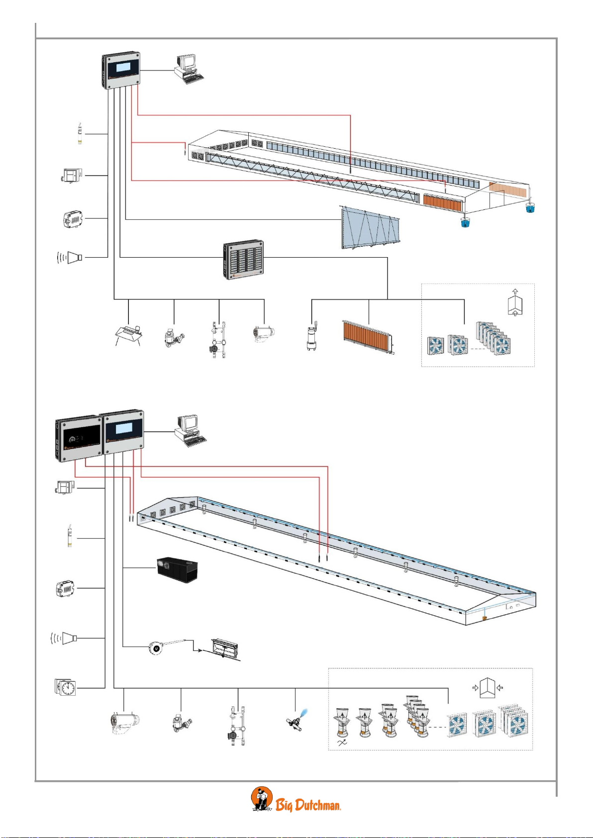
Figure 1: Outline of connections 307pro Combi-Tunnel
378
307pro
Aux. sensor
Pressure sensor
CO2
Alarm
Temperature sensor
Humidity sensor, Temp. sensor
Outside temp. sensor
Humidity sensor, Temperature sensor
Tunnel cooling sensor
Wall inlets
Front Rear
Rack and pinion
Front
Rear
Side mode
Tunnel mode
Step 1 Step 16
Step 1 Step 2 Step 16
Cooling pump
Cooling
Magnet valve
Local heat
Relay heat
Heating shunt
8 Circuit Diagrams and Cable Plans
307pro Climate computer
Figure 2: Outline of connections 307pro Tunnel
Figure 3: Outline of connections 307pro
Humidity sensor Temperature sensor
Outside temp. sensor
Tunnel cooling sensor
Aux. sensor
Pressure sensor
CO2
Alarm
Step 1 Step 2 Step 16
Cooling pump
Magnet valve
Local heat
Relay heat
Blowheater
Tunnel cooling
Heating shunt
Tunnel mode
Tunnel cooling
307pro
NH3
Pressure sensor
CO2
Relay heat
Blowheater
Magnet valve
Heating shunt
Cooling
Step 1 Step 2 Step 3 Step 6 Step 7 Step 16
Side mode
Humidity sensor, Temperature sensor
Outside
temperature sensor
Temperature sensor
Alarm
24-hour clock
307pro
378
Heat recovery unit
Acuator Wall inlet
Circuit Diagrams and Cable Plans 9
307pro Climate computer
1 Mounting of 307pro together with 378
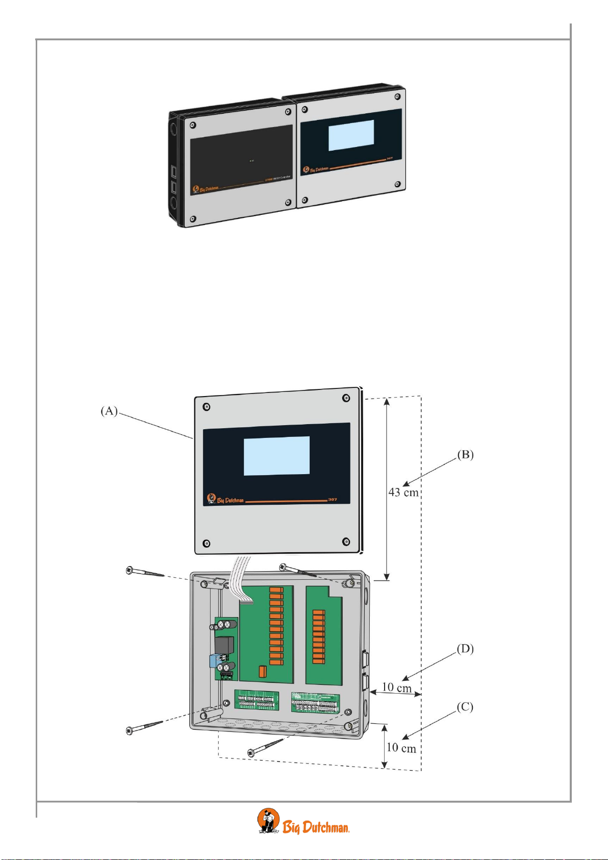
Figure 4: Mounting of 307pro with 378
2 Mounting of 307pro
1) Place the computer with the display (A) at eye level for the daily user.
2) Remember free space around the cabinet:
•43 cm (B) so that the front panel can be placed on top of the cabinet base during service.
•10 cm (C) below the cabinet base for air cooling.
•10 cm (D) on the right side for operation of the AUT/MAN (Auto/Manual) change-over switches.
Figure 5: Mounting of 307pro
378
307pro
10 Circuit Diagrams and Cable Plans
307pro Climate computer
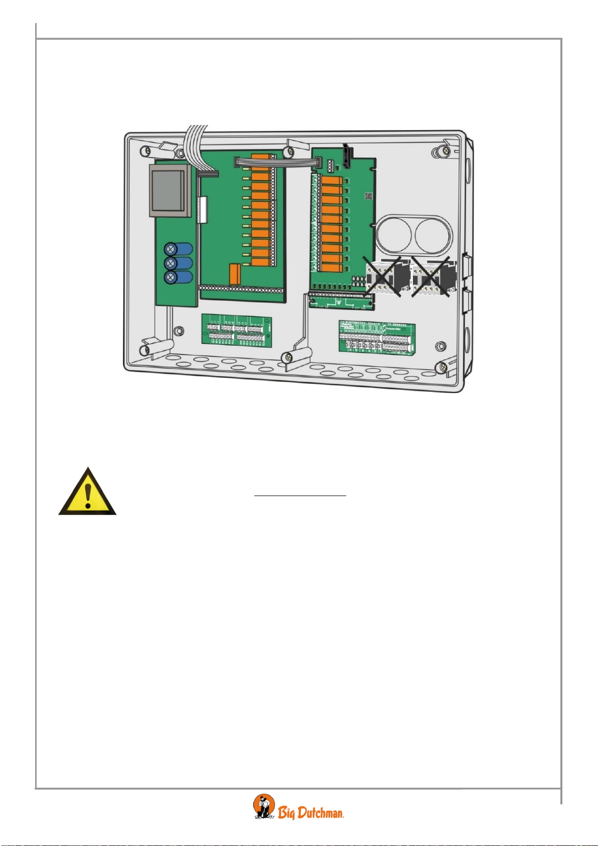
2.1 Mounting of Auxiliary Contactor
Do not place the contactors in the climate computer. The contactors cause electrical disturbance which can
make the computer reset/restart.
Place the contactors in an external box next to the climate computer.
Figure 6: Mounting of auxiliary contactor
Contactor or auxiliary relay must not be installed in the climate computer.

Circuit Diagrams and Cable Plans 11
307pro Climate computer
2.2 Mounting of Extra 24 V Power Supply
2.2.1 Power Supply 24 V, 2.1 A in Box
The extra power supply (A) is mounted at the side of the computer or in the vicinity of it
Figure 7: Mounting of extra 24 V power supply in box
2.2.2 Power Supply 24 V, 2.1 A, Printed Circuit Board
The extra power supply (B) (power supply 24 V 2.1 A, printed circuit board) can be mounted in a pre-existing
extension box together with the I/O module.
Figure 8: Mounting of extra 24 V power supply, printed circuit board
3 Mounting of Emergency Opening
See Technical Manual regarding the emergency opening.
12 Circuit Diagrams and Cable Plans
307pro Climate computer
4 Mounting of Climate Sensors
Never use a plug on the DOL 12 temperature sensor as a bad connection here
could have disastrous results.
Always use reinforced house wiring cable, minimum 1.5 mm2, to avoid
rodent attack.
Never use shrink-on sleeves when splicing wires inside the livestock house.
Use a contact box.
Placement of sensors inside the house
Place the sensor in the centre of the house.
In case of animals on floor the sensor is placed 1 metre over the animals (make sure the animals
cannot reach sensors).
Two-climate houses: the sensors must hang halfway between the covered area and the slats.
Remember that temperature, humidity, alarm and emergency sensor should be placed together, if
possible use house board for sensors (available as accessory).
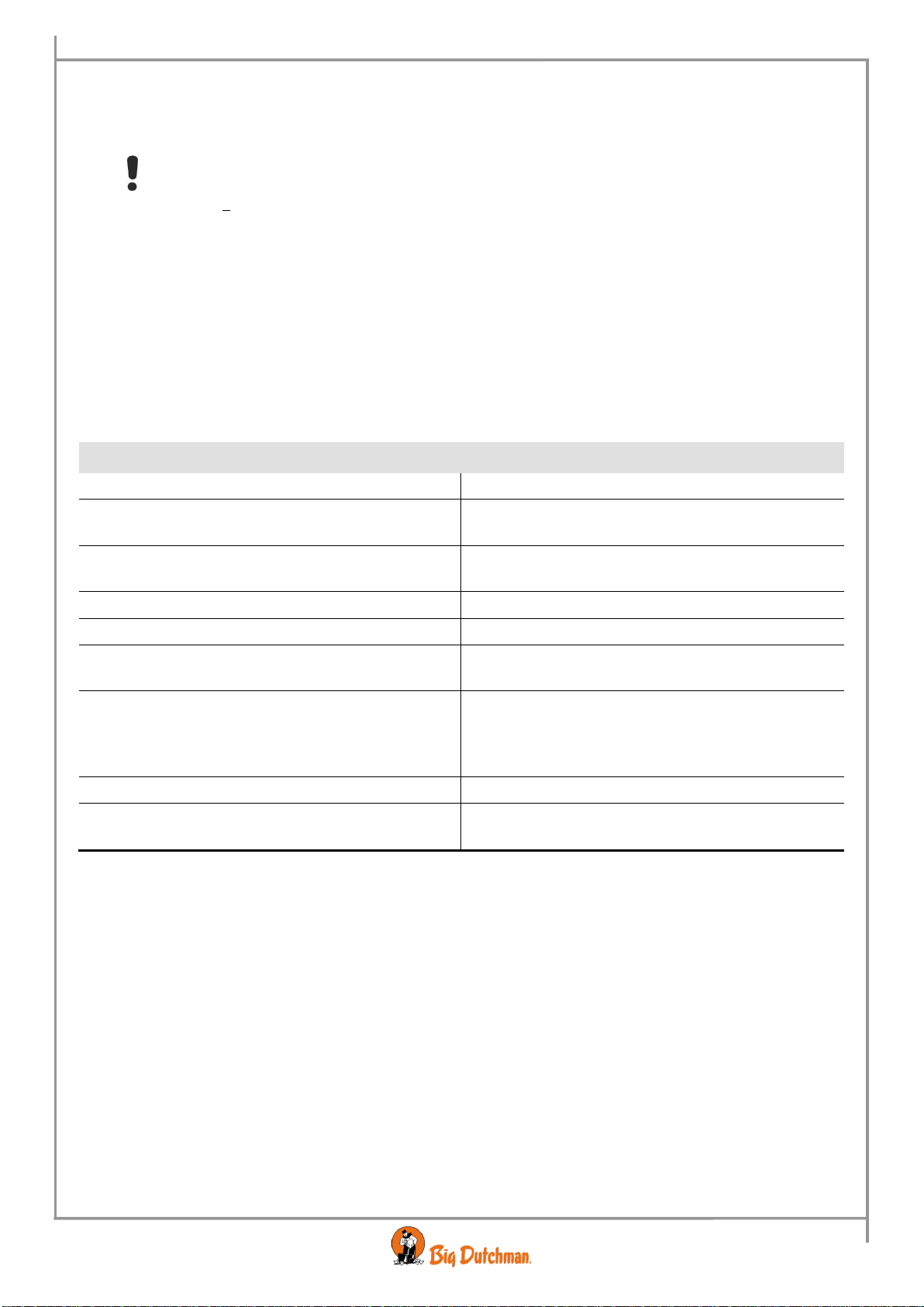
The sensor is not to be placed
Reason
Above penning equipment.
The animals may be able to reach them.
At feed dispenser/feed trough/transponder station.
Heat and humidity will rise to the position of the
sensors.
Near covering.
Heat from the covered area will rise to the position of
the sensors.
Near spraying system.
Water and humidity will affect the sensors.
Near cooling system.
Water and humidity will affect the sensors.
In a draughty area. The sensor is not to be directly
affected by the air intake.
Measures the wrong temperature in the house.
Not where sunrays can shine on the sensor through
windows.
Take into account that the altitude of the sun varies
with the season/time of day.
Measures a too high temperature. Too much
ventilation.
Above electric heater in the section.
The heat rises to the position of the sensors.
Above or in a position where it in some way will be
affected by the heating system/heating pipes.
The heat rises to the position of the sensors.
Placement of sensors outside the house
We recommend mounting sensors with a radiation shield (available as accessory).
On the shady side of the house to avoid the sun. Take into account that the altitude of the sun varies
with the seasons.
As much in the open as possible, but protected from rain and snow.
Circuit Diagrams and Cable Plans 13
307pro Climate computer
INSTALLATION GUIDE
5 Electric Connection
The installation, service and troubleshooting in connection with electrical equipment must be
carried out by specialists in accordance with applicable national rules - in Europe in accordance
with EN 60204-1 and other applicable EU rules
The installation of a supply isolator is required for each motor and power supply, so maintenance of
electrical equipment can be carried out in a dead environment. Supply isolator is not supplied by
Big Dutchman.
Always use reinforced house wiring cable, minimum 1,5 mm2, to avoid rodent attack.
5.1 Connecting Cables
Connect cables according to the three basic wiring diagrams which correspond to the emergency opening of the
system.
5.2
Connection of backup units to 307pro
In areas with an unstable power supply, one of the following backup units can be mounted in front of
307pro to compensate for frequent power failures.
With/without
Emergency Opening 378
Type of backup unit
Comment
With 378
134792 Mini UPS for climate
computer, backup function
Supplies the house computer in max. 5 mins
in the event of power failure.
Without 378
134718-02 Mini Power Backup
Unit, 20V 1A
Supplies the house computer in 5 mins on
average in the event of power failure for
max. 0.5 - 3 hours.
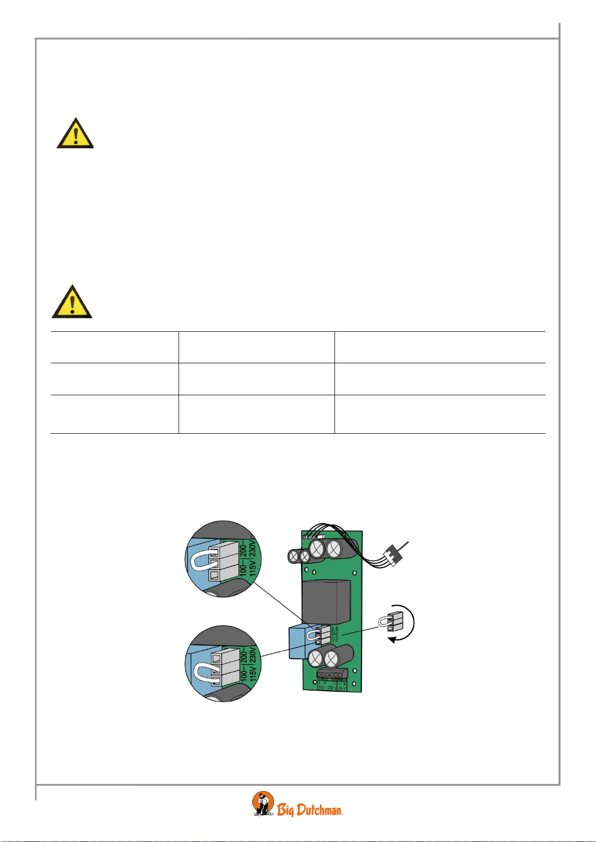
5.3 Setting of Mains Voltage
IMPORTANT Before you connect the mains voltage, it is important to set the voltage in the
computer so that it corresponds to the voltage level in the local house.
200-230 V Leave the plug in (factory setting)
100-115 V Move the plug to 100-115 V
Figure 9: Power supply: Setting of mains voltage
NB Fan speed controller modules can only operate at 230 V.
Connect the mains voltage. After a few minutes, the computer is ready to be set.
14 Circuit Diagrams and Cable Plans
307pro Climate computer
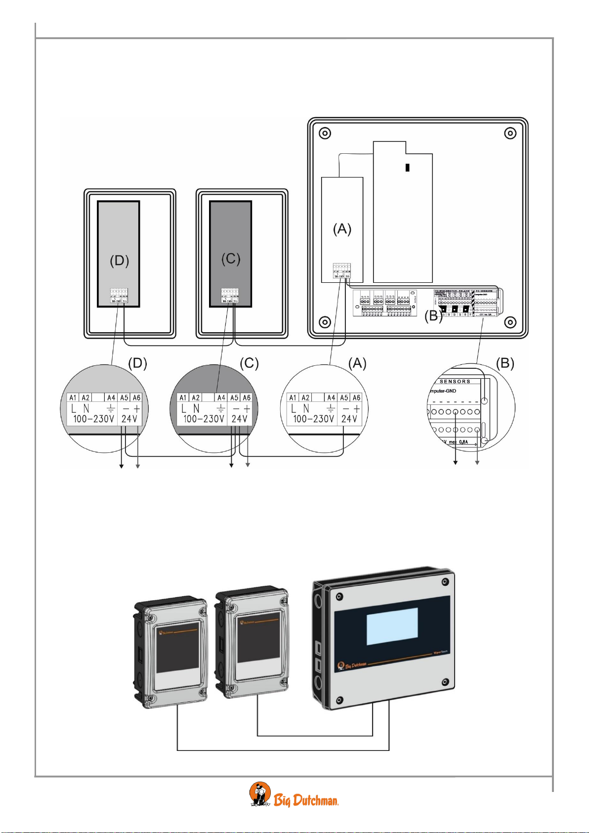
5.4 Connection of extra 24 V power supply
Internal power supply (A) may only supply factory-installed modules.
In case of a greater power consumption than 0.8 A from the loop module (B), an extra power supply (C) must
be used and possibly (D).The A5 minus terminal is connected in parallel (terminal A5 to A5).
Figure 10: Connection of extra 24 V power supply
Connect power supply to 307pro with a multi-conductor cable.The connected products determine the number of
conductors in the multi-conductor cable.
The multi-conductor cable is used for input and output signals from the connected products and to the minus
wire of the power supply.
Figure 11: Connection through multi-conductor cable between power supply and 307pro
+24 V max 2,1 A
+24 V max 2,1 A
+24 V max 0,8 A
Multi-conductor cable
Multi-conductor cable

Circuit Diagrams and Cable Plans 15
307pro Climate computer
5.5 Connection of seven or more I/O modules
A maximum of 10 I/O modules may be connected.
If connecting 7 or more I/O modules, the ribbon cable must be supplement with two wires (D) must be
minimum of 1.0 mm2between the internal power supply (A) and the terminal block on the seventh I/O module.
Figure 12: Connection of seven or more I/O modules
16 Circuit Diagrams and Cable Plans
307pro Climate computer
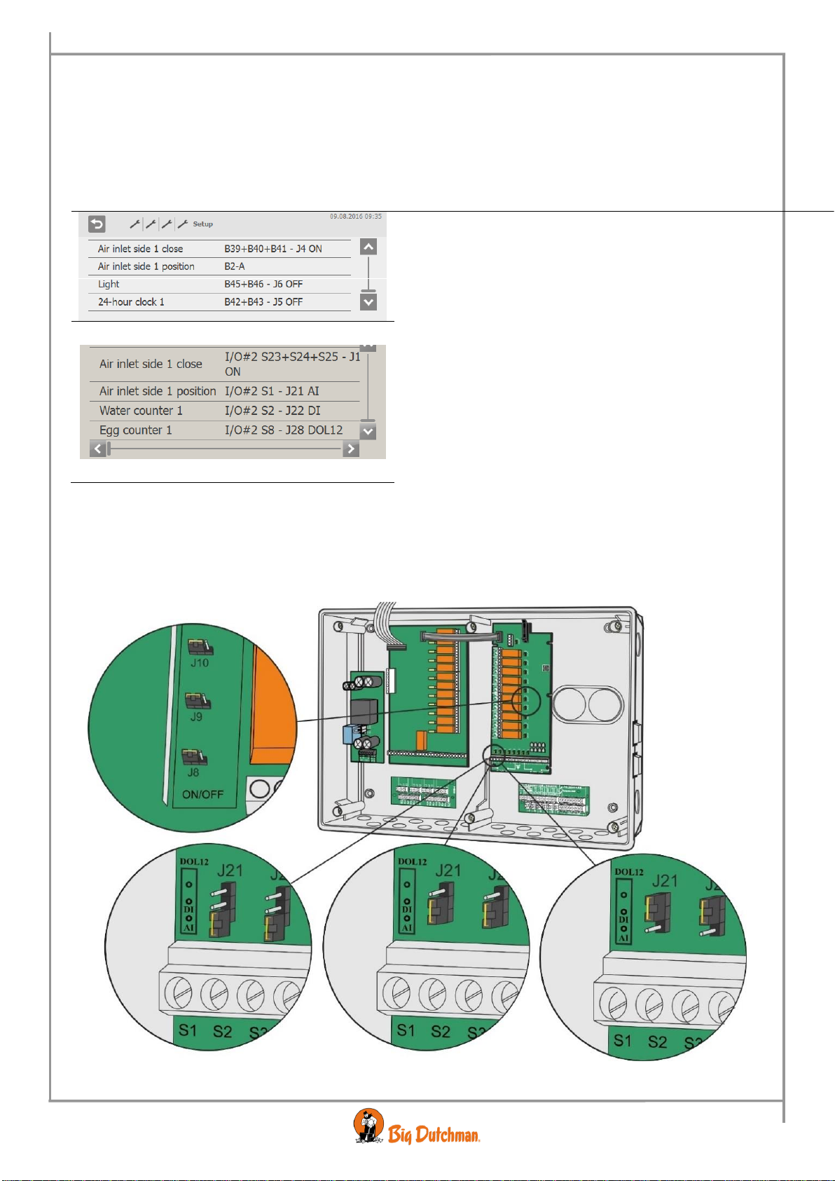
6 Connection through Installation Menu of the Computer
The connection terminals in the 307pro computer are universal, allowing different components to be connected to
the individual terminals. Therefore, consider the circuit diagrams in this document as examples only.
The 307pro computer’s installation menu (Technical/Setup/Show connection) shows precisely the terminals to
which components should be connected.
Note V DC supply, ground terminal/minus terminal clamp for sensor and feedback is not displayed.
Main board including jumper.
ON =
Emergency opening can override relay so inlet
opens.
OFF =
Factory setting.
Emergency opening cannot override relay.
I/O module including jumper.
ON =
Emergency opening can override relay so inlet
opens.
OFF =
Factory setting.
Emergency opening cannot override relay.
AI =
Analogue input.
DI =
Digital input
DOL 12 =
DOL 12
When wiring diagrams say “See connection in 307pro menu: Technical/Setup/Climate/Show connection”, they
refer to the computer indications. See also Technical Manual.
6.1 Positioning of jumper
ON/OFF
AI
DI
DOL 12

Circuit Diagrams and Cable Plans 17
307pro Climate computer
6.2 Printing the Installation Setup via the PC Simulator
The software for the 307pro house computer is also available as a simulator variant for installation on a PC.
Having set up the installation menu using the PC simulator, the setup can be saved as a semicolon delimited file
on the PC. The file thus contains a list of the installed components and the connection terminals to which they
are to be connected in the house computer.
The file can be opened using MS Excel or a text editor
and be printed in the usual way.
Open the PC simulator and select the Setup menu.
Choose where to file the setup file.
USB drive:
Corresponds to the house computer's filing of e.g.
log files and setup files on a USB flash drive.
Can be set in the PC simulator to save on a USB
flash drive or locally on the PC.
Folder:
You can also choose to save the file in a folder.
Save the file using the name: ConnectionList.csv.
Each time the user enters the
Technical/Setup/Show connections menu, the
PC simulator saves a version of the current setup
on the file.
If the file already exists, it will be overwritten.
There can only be one ConnectionList on the
same USB.

18 Circuit Diagrams and Cable Plans
307pro Climate computer
7 Setting of CAN Addresses
Hvert modul (I/O-modul og vejemodul) skal have en bestemt CAN-adresse for at computeren kan
kommunikere med det. Adressen på det enkelte modul svarer til modulnummeret.
I menuen Teknisk/Opsætning/Installation/I/O moduler/Ekstra I/O-moduler
the I/O-modules address switch
(Rotary Switch) as follows:
Module 1Type 10 10 RL Address = 1
Module 2Type 10 10 RL Address = 2
Module 3Type 10 10 RL Address = 3
Module 4Type 10 10 RL Address = 4
Module 5Type 10 10 RL Address = 5
Module 6Type 10 10 RL Address = 6
Figure 13: Setting of CAN-Addresses
0
2
1
3
4
5
6
7
8
9
A
B
C
D
E
F
I/O-modul
Circuit Diagrams and Cable Plans 19
307pro Climate computer
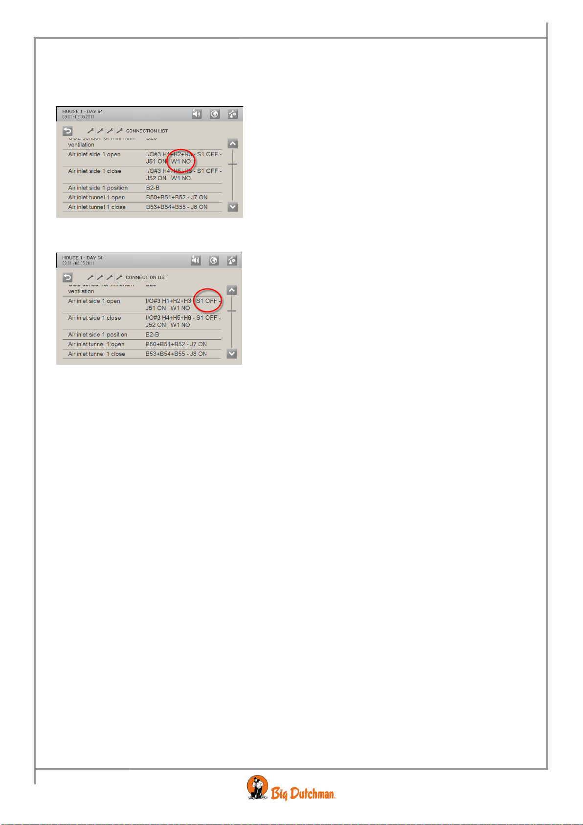
7.1 Settings for Winch Motor
When you connect winch motors, the following must be set as shown in: Technical/Setup/Show installation.
LO-power relay module:
Winch motor YES / NO, jumpers W1 - W5:
•YES= Inverts one of the relays in the pair of relays
so that it matches winch motor and emergency
opening
•NO = The relay matches e.g. heating and fans.
Override switch modules:
WINCH-MOTOR BLOCKED: slide switch: S1 - S5
•ON = For winch motor. Prevents paired activation
of relays and quick changes in direction out of
consideration for the lifetime of the relay contacts
•OFF = For e.g. heating and gable fans. The relays
can be activated unobstructed.
•A winch motor must always be installed on one of the following pairs of relays: 1st + 2nd relay, 3rd +
4th relay, 5th + 6th relay, 7th + 8th relay or 9th + 10th relay
•The HI-power relay module with make contacts can control e.g.
fan
heating
230 V winch motor
•The LO-power relay module with make contacts can control e.g.
fan
heating
230 V winch motor
24 V DC winch motor with emergency opening
•The switch module is used together with both the HI-power relay module and the LO-power relay
module
20 Circuit Diagrams and Cable Plans
307pro Climate computer
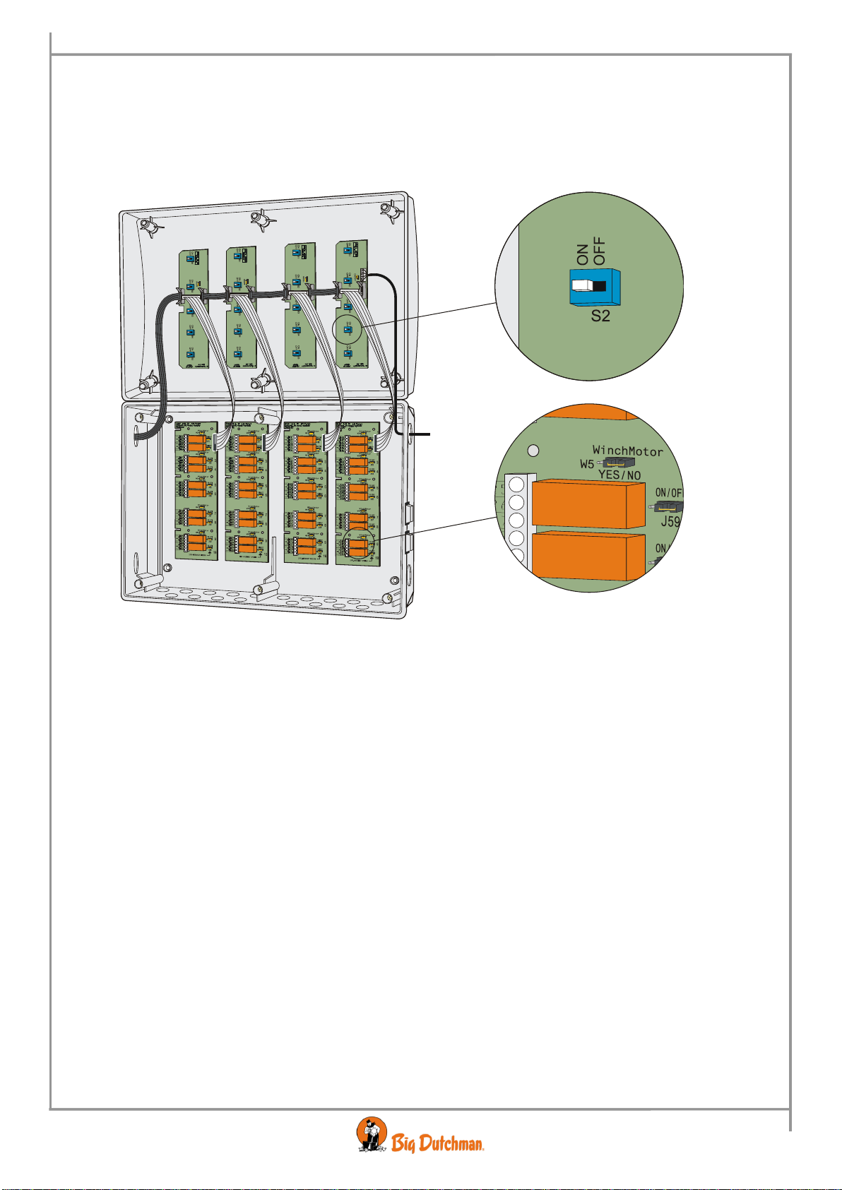
Example:
If a 24 V winch motor is installed on 9th and 10th relay, the following must be set:
•Set the W5 jumper on the LO-power relay module to YES
•Set the S5 slide switch on the override switch module to ON
There are no settings on the HI-power relay module and it cannot control 24 V winch motors either.
Figure 14: Settings for winch motor
Table of contents
Popular Computer Hardware manuals by other brands


EEPD
EEPD EM PRO mini E Reference manual

CAME
CAME ZG5 installation manual

Cypress Semiconductor
Cypress Semiconductor NoBL CY7C1470BV33 Specification sheet

TRENDnet
TRENDnet TE100-PCBUSR - DATA SHEETS Quick installation guide

Advantech
Advantech AIMB-786 Startup manual

Texas Instruments
Texas Instruments INA234EVM user guide