big ideas JP-02 User manual
JP-02 Infrared motion sensor
Instruction
SPECIFICATION:
Power Source: 220-240V/AC Detection angle: 360°
Power Frequency: 50Hz Detection Range: 50%, 75%, 100% (choice)
Daylight sensor: <3-2000LUX (selectable) Detection Distance: 20m max(<24℃)
Hold Time: Min.10sec±3sec Working Temperature: -20~+40℃
Max.30min±2min Working Humidity: <93%RH
Rated Load: Max.2000W Installation Height: 2.2-6m
1000W Detection Moving Speed: 0.6-1.5m/s
Power Consumption: approx 0.5W
FUNCTION:
This sensor requires a remote control for setting all parameters! About the details kindly see in “IR REMOTE
CONTROLLER”.
Can identify day and night: The user can adjust working state in different ambient light. It can work in the daytime and at night
when it is adjusted on the “ 2000LUX” . It can work in the ambient light less than 10LUX, when it is adjusted on the “10LUX”.
Detection range adjustable :It offers 3 levels (50%,75%,100%).
Time-Delay is added continually: When it receives the second induction signals within the first induction, it will restart to time
from the moment.
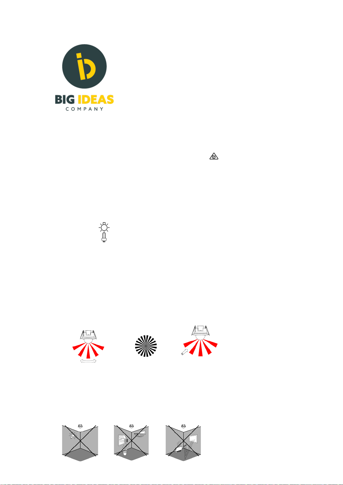
Good sensitivity Poor sensitivity
INSTALLATION ADVICE:
As the detector responds to changes in temperature, avoid the following situations:
Avoid pointing the detector towards objects with highly reflective surfaces, such as mirrors etc.
Avoid mounting the detector near heat sources, such as heating vents, air conditioning units, light etc.
Avoid pointing the detector towards objects that may move in the wind, such as curtains, tall plants etc.
This product complies with Australian standards and is RCM approved E3876

CONNECTION:
Unload the transparent vinyl cover which is at the bottom of the sensor.
Loose the screws in the connection terminal, and then connect the power to connection terminal of sensor according to
connection-wire diagram.
Install back the transparent vinyl cover into the original location.
Fold the metal spring of the sensor upwards, until they are in “I” position with sensor, and then put the sensor into the hole or
installation box which is on the ceiling and has the similar size with the sensor. Releasing the spring, the sensor will be set in
this installation position.
After finishing installing, turn on the power and then test it.
Step1 Setp2 Step3
Note: you can cut the plastic cover whatever shape you want and make different detection range. (refer to right figure)
Battery replacement
Pull out the battery holder
Put in a new battery (3V)
SENSOR INFORMATION:
CONNECTION-WIRE DIAGRAM (See the right figure)
•Note do notput the switch on the power supply side of the sensor
This sensor is only designed tohave the switch onthe load output
FUNCTION:
This sensor requires a remote control for setting allparameters! About the
details kindly see in“IR REMOTE Remote
Height of installation: 2.2-6m Detection Distance: Max.20m
JP-02

Remote control
The sensors can be programmed using a remote controller as shown.
The remote controller can be in one of two states – LOCKED or UNLOCKED. When locked, it does not send
information to the sensor. To change sensor settings, you need to make sure that the controller is unlocked.
You can lock and unlock the controller with the LOCK/UNLOCK button (lock button):
command to the sensor a red LED in the right top corner
When the controller is unlocked, every time it
sends a briefly flashes.
location of
the red LED
When the controller is locked, the remote controller ignores all buttons except the LOCK/UNLOCK one and the red LED does not flash.
The controller automatically enters the LOCKED state after 5 minutes from the time it was last used.
Before starting programing a sensor, press the lock button and observe the red LED. If it flashes once, the remote controller was
previously locked, now it is unlocked and you can start programming. If it flashes three times, the remote controller was already
unlocked and now it is locked. Press the lock button again, you will notice a single flash of the red LED and the controller is now
unlocked and ready.
NOTE: The lock button affects only the remote controller, NOT the sensor.
When programming the sensor, observe the red LED in the controller. On each press of any button the LED in the controller should
briefly flash once. If it does not, the controller is locked or its battery is flat and needs to be replaced.
If you press a sensor programming button on the controller, the red LED in the sensor should flash three times. This indicates that
the required programming command has been accepted. Note that a sensor may be in a condition where it does not accept certain
programming commands. It is re3commended to press each programming button twice, first time while watching the controller to
make sure that it sends the command out and the second time while watching the sensor to confirm that the sensor accepted the
command.
Sensor modes
The sensor can be in one of three modes:
ON – the load is permanently ON, no motion detection. You can recognize this mode by the fact that the load stays on whether
there is movement or not.
OFF – the load is permanently OFF, no motion detection. This mode is indicated by the sensor red LED flashing briefly once every 2
seconds. AUTO – the sensor detects motion and controls the load on and off in accordance with the parameters programmed into it.
If the sensor LED does not flash three times in reply to a programming command, it is in a mode where it does not accept the
programming command you sent. In modes ON and OFF the sensor will accept only ON, OFF, AUTO, TEST and RESET and will
ignore all other commands. In mode AUTO the sensor will accept all programming commands.
Sensor operation
The sensor measures the ambient light level and detects movement.

The sensor distinguishes two external conditions – ‘day’ and ‘night’, based on the level of ambient light. If it detects ‘day’, it will not
activate the load even if it detects movement. You have to program the level of ambient light below which the sensor activates the
load. Using the controller, you can program the ambient light level below which the sensor detects ‘night’ and above which it detects
‘day’. You can choose the following light levels: 10LUX, 50LUX, 150LUX and 2000LUX. 2000LUX level equals ambient light when you
point a very strong light source directly at the sensor. If you choose 2000LUX level, the sensor will activate the load as programmed
for all light conditions, day and night.
If you choose too low a light level, the sensor will not switch the load (lights) even if you may consider the location being in the dark.
If you choose too high a light level, the sensor will operate and activate light while it is still enough of day light.
The LUX light level number is meaningless to most end users. To pick the right level, the sensor supports an ‘eye’ function,
activated by the ‘eye’ button on the controller:
Use the ‘eye’ function when the ambient light is on a boundary between ‘day’ and ‘night’. Make sure that the
load is off, press the ‘eye’ button and check that the sensor responds by flashing
its red LED. NOTE: To use the ‘eye’ function, the load must be OFF.
Programming sensor parameters
Sensor parameters determine conditions under which the sensor switches the load on and off. These parameters affect sensor
operation only while it is in AUTO mode. If the load is ON while you change any parameter, the new value will take effect only after the
load goes OFF. If the load is OFF, the new value takes effect immediately.
You can program three parameters:
- detection range – 100%, 75%, 50%. (It is unclear from available documentation what this parameter actually means. Unclear meaning
precludes any testing.)
daylight threshold - the level of ambient light below which the sensor detects movement and controls the load, as
described earlier. - hold time - the length of time the load stays ON after the sensor detects movement, in the range 10
seconds to 30 minutes. If the
sensor detects movement while the load is ON, it restarts the load timer. As an example, if the ON time is set to 10 sec
and during these 10 seconds the sensor detects movement, it will start the timer again. The sensor will only go OFF if
there is no movement detected over the hold time, in this case over a 10 seconds period.
This product complies with Australian standards and is RCM approved
- TEST. This button puts the sensor into a test state. It is intended for factory testing and should not be used by the installer or the end
user. If you press this button, operation of the sensor will be unpredictable to you. To recover, press the RESET button. (It would
take a lot of time to crack sensor operation while in test mode and I do not believe that it is worth doing. At the first glance this operation
is at least strange if not outright bizarre.)
RESET. This button restores factory settings and allows for recovery from the test state. Factory settings for JP-02 are: hold time 10
seconds, daylight threshold 2000LUX.
-While 10 seconds hold time may be reasonable, in most cases 2000LUX is not a good choice. Either program one of the three levels
10LUX, 50LUX and 150LUX or use the ‘eye’ function.
Subject to changes at any time 010621
Big ideas company Pty Ltd
Table of contents
Popular Accessories manuals by other brands

nLight
nLight nCM ADCX RJB manual

CORONA
CORONA MC 47900 Assembly instructions

INNOBIZ
INNOBIZ musilia Instructions for use

Heat Controller
Heat Controller Flow Controllers Installation, operation & maintenance manual

Osram
Osram DALI SENSOR LS/PD LI G2 manual

Oregon Scientific
Oregon Scientific EMR898A user manual


