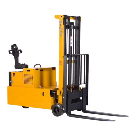
Big Joe CB22 User manual

OPERATOR’S MANUAL
Big Lift LLC
www.bigjoeforklifts.com BL-COUNTERBALANCE-1016
08/02/2018
COUNTER-
BALANCE
LIFT TRUCK


1
FOREWORD
As a lifttruck operator, you are respon-
sible for a machine that is useful, pow-
erful, and can be hazardous if not
operated as described. Your Big Joe
truck may weigh more than some cars,
depending on the model. Observing
and practicing the safety warnings in
this manual cannot be overempha-
sized.Justknowingthewarnings,how-
ever, is no substitute for common
sense. Using your common sense will,
in almost all cases, prevent accidents.
Think of the truck as your own. In this
way you will learn its capabilities and
limitations.
This manual is intended to remain with
the truck at all times as a handy refer-
enceguidetooperation.Detailedmain-
tenance procedures are found in the
parts and service manual for the spe-
cific truck model, and are to be per-
formed only by a qualified technician.
For further information on obtaining a
completepartsandservicemanual,see
page 25 of this manual.
The operator who knows his truck will
learntospotproblemsastheydevelop.
Thisisaccomplishedby performingthe
Daily Checks and reporting any prob-
lems to the designated authority.
TABLE OF CONTENTS
SAFETY SYMBOLS..............................................................................................2
GENERAL DESCRIPTION....................................................................................2
NAME PLATE AND WARNING DECAL ...............................................................2
LOAD CAPACITY..................................................................................................5
BEFORE OPERATION..........................................................................................6
INSTRUMENTS AND CONTROLS - CB22 & CB33.............................................8
OPERATION........................................................................................................11
Forward and Reverse Travel and Speed Control ...............................11
Steering..................................................................................................13
Stopping.................................................................................................13
Parking...................................................................................................14
Battery Charging...................................................................................14
Load Handling .......................................................................................15
Moving a Disabled Truck......................................................................15
NOTICE - OBTAINING A PARTS AND SERVICE MANUAL..............................25

2
SAFETY SYMBOLS
WARNING and CAUTION are both signal words intended to alert the viewer to the
existence and relative degree of a hazard. They are both preceded by a safety alert
symbol consisting of an exclamation mark enclosed by a triangle.
A Warning indicates a hazard which could result in injury or death if proper precau-
tions are not taken.
A Caution indicates a reminder of routine safety practices.
A prohibition slash (circle with diagonal slash through it) indicates a procedure or
actionthatshouldnotbeperformedunderanycircumstances,asbothpersonalinjury
and/or damage to equipment will result.
GENERAL DESCRIPTION
Trucks in the Big Joe Counterbalance
seriesutilize a weightedframetocoun-
terbalance the load. Most models are
equipped with tilt cylinders used to tilt
the mast back during transport.
Control for steering, braking, forward
andreversetravel,hornandspeedcon-
trolarealllocatedonthecontrolhandle.
All trucks feature an automatic high
speed cut-off circuit which locks out
highspeedwhentheforksareelevated.
Trucks in this series may vary in load
capacity, battery arrangement, instru-
mentation and lift/lower controls,
depending on model and options.
NAME PLATE AND WARNING DECAL
Name plate and warning decal loca-
tions may vary between models, but
they are always near the steering arm
within sight of the operator.
Ifthenameplateorwarningdealarelost
or damaged they should be replaced
immediately. Have your supervisor or
the designated authority contact Big
JoeAuthorizedDealerforreplacement.
Thename plate shows the model num-
ber, serial number, truck type, battery
type, voltage, minimum weight, and
maximum lift height. It also contains
information on the load capacity and
loadcenter.Thewarningdecalcontains
warnings which also appear, with illus-
trations,in theOperationsectionofthis
manual.

3
CB22 Name Plate and Warning Decal Locations - Typical
CB33 Name Plate and Warning Decal Locations - Typical
R7304

4
PDC Name Plate and Warning Decal Locations - Typical
This truck is equipped with a battery. Read and heed the following warning plus any
other warnings located near or on the battery.
WARNING:

5
LOAD CAPACITY
The further the load center is from the
backrest, the lower the load capacity.
Theload centermust alsobe no higher
thanthatspecifiedabovetheliftingsur-
face(Top side offorks).Forexample,a
load capacity of 3,000 pounds with a
loadcenterof24inchesmeansthatthe
truck can be used to lift 3,000 pounds
onlywhentheload’scenterofgravity is
nomorethan24inchesfromthefaceof
theforksor24inchesabovethetopside
of the forks. Note that a truck undergo-
ingspeedchangesis lessstablethana
standing truck. If you are not sure that
the truck can lift a certain load, consult
your supervisor or the designated
authority.
Load Center
R3814

6
BEFORE OPERATION
The table on page 7 covers important
inspection points on trucks which
should be checked prior to operation.
Depending on use, some trucks may
require additional checks.
The illustration below shows a sample
format for a Operator Checklist, which
canbemodifiedasnecessarytofityour
operation.
Periodic maintenance of this
truck by a qualified service
technician is required.
A qualified service technician
should check the truck monthly
for proper lubrication, proper
fluid levels, brake maintenance,
motor maintenance and other
areas specified in the parts and
service manual maintenance
section.
If the truck is found to be unsafe
and in need of repair, or contrib-
utes to an unsafe condition,
report it immediately to the des-
ignatedauthority.Donotoperate
it until it has been restored to a
safe operating condition. Do not
make any unauthorized repairs
or adjustments. All service must
be performed by qualified ser-
vice technician.
Sample of Operator Check List
WARNING:
WARNING:
WARNING:
R6235

7
Operator Checks
ITEM PROCEDURE
Transmission and hydraulic
systems Check for signs of fluid leakage.
Forks Check for cracks and damage and that they
are properly secured.
Chains, cables and hoses Check that they are in place, properly secured
and not damaged.
Guards and load backrest Check that safety guards are in place, prop-
erly secured and not damaged.
Safety signs Check that warning labels, nameplate, etc.,
are in good condition and legible.
Horn Check that horn sounds when operated.
Steering Check for binding or looseness in steering
arm when steering.
Travel controls Check that speed controls on control handle
operate in all speed ranges in forward and
reverse and that belly button switch functions.
Wheels Check drive wheel for cracks or damage.
Move truck to check load wheels for freedom
of rotation.
Hydraulic controls Check operation of lift and lower, and tilt to
their maximum positions.
Brakes Check that brakes actuate when steering arm
is raised to upright position, and when lowered
to horizontal position.
OPTION ON PDC TRUCKS: Check that
dynamic brake (if so equipped) actuates when
dynamic brake pushbutton on control handle
is pressed.
Deadman/Parking brake Check that steering arm raises to upright posi-
tion when released and brake applies.
Battery disconnect Check that battery can be disconnected and
reconnected. Check for connector damage.
High speed limit switch Allow for enough space to operate truck in
high speed. Elevate forks approximately two
feet, then test drive truck to check if high
speed is cut out.

8
INSTRUMENTS AND CONTROLS - CB22 & CB33
The steering arm and control handle
provide controls for steering, forward
and reverse speed control, braking,
horn,tiltingandraisingandloweringthe
forks. Control handles on all models
have a “belly-button” reversing switch
whichreversesthedirectionofthetruck
upon contact with the operator.
Detailed operating instructions are in
the Operation section of this manual.
A battery disconnect is mounted near
thesteeringarm.Pullingthedisconnect
removesall power from truck circuits in
the event of an emergency.
CB22 Control Handle
CB33 Control Handle
R7305
R7306

9
INSTRUMENTS AND CONTROLS - PDC
The steering arm and control handle
provide controls for steering, forward
andreversespeedcontrol,braking,
and
horn. Control handles on some
models
have pushbuttons for raising
and low-
ering the forks, and for an
additional
"dynamicbrake" independentfromthe
mechanical brake (dynamic brake no
longeravailableonnewtrucks).Control
handlesonallmodelshave a
"belly-but-
ton" reversing switch which reverses
the direction of the truck
upon contact
with theoperator.
Detailed operating instructions are in
the Operation section of this manual.
A battery disconnect is mounted near
thesteeringarm.Pullingthedisconnect
removesallpowerfrom truck circuitsin
the event of an emergency.
PDC Control Handle
All models come standard with a lift/
lower control lever mounted near the
steering arm. Some models have addi-
tional control levers for operating a tilt
mechanismwhichtiltsthemastforward
or back. Other models have additional
controlleversfortheoperationsofaddi-
tional accessories.
Lift/Lower and Tilt Control Lever
Optional Features
R7306

10
Theoptionalremotelift/lower control
(if
equipped) allows the operator to raise
andlowertheforkswhile standingaway
from the control handle.
Optional Remote Lift/Lower Control
Other options are the battery capacity
indicator, hourmeter and keyswitch
whichmountonthepanelnear the
con-
trol handle. The battery capacity
indi-
cator monitors the battery discharge
rate to indicate the remaining
battery
capacity. The hour meter
records the
accumulated hours that
electrical
energy is being drawn from
the battery
to run the pump and drive
motors. The
keyswitch provides
added security to
the truck,preventing
unauthorized per-
sonnel from operating themachine.

11
OPERATION
Forward and Reverse Travel and
Speed Control
All directional and speed controls are
located on the control handle.
Forward and reverse are controlled by
rotating the speed control lever as
shown. The lever is spring loaded to
returntoneutralwhenreleased.Further
rotation in either direction will progress
the truck from slow to maximum travel
speed.
Tochangedirectionsortostopthetruck,
rotate the speed control lever in the
opposite direction. The truck will come
to a stop and then, unless the controls
are returned to the center neutral posi-
tion, accelerate in the opposite direc-
tion.
CB22 Control Handle
CB33 Control Handle
R7305
R7306

12
PDC Control Handle
R3961

13
Steering
Moving the control handle (which con-
nectstothesteeringarm)rightorleftwill
turnthetruckrightorleft.Whenmaneu-
vering around corners, make square
turns and be sure there is
adequate clearance.
Stopping
Stopthetruckasgraduallyaspossible.
Unnecessary rapid stopping could be
hazardous. Load could become unsta-
ble.
Therearefourpossiblewaystostopthe
truck:
1. Plugging: This electrical braking
function consists of rotating the
speedcontrolleverin theopposite
direction of travel and then releas-
ing it when the truck stops. Plug-
gingisaconvenientwaytostopthe
truck during normal operation. If
the control is not released, the
truckwillaccelerateintheopposite
direction.
2. Steering arm: The brake is fully
applied by lowering or raising the
steering arm. All traction control
powerisshutoffwhenthebrakeis
engaged.Whenthesteeringarmis
in the upright position, the brake
actsas a parkingbrake. Deadman
braking occurs when the handle is
released and spring action raises
steering arm to the upright posi-
tion.
CB22 & CB33 Steering Arm Braking Positions

14
PDC Steering Arm Braking Positions
Steering Arm Braking Positions
3. Regenerative Braking (CB22 &
CB33):Ifthespeedcontrolleveris
released, the truck automatically
brakes regeneratively. When the
speedisbelow0.5MPH,thebrake
applies.
4. Dynamic Brake (PDC Only): -
(Dynamic brake is no longer avail-
able on new trucks). The dynamic
brake (optional) serves as a sec-
ondarybrakingsystemcompletely
independent from the mechanical
brake.Pressingthedynamicbrake
pushbutton applies a constant DC
voltageacrossthedrivemotorfield
coils to stop the motor.
The dynamic brake pushbutton
shouldnotbeheldinplacelonger
thanoneortwoseconds.Exces-
sive use may blow the 40 Amp
fuse, which will render dynamic
brake inoperative
Parking
Whenparkingthetruck,donotobstruct
traffic lanes or aisles.
1. Park the truck in its designated
parking area.
2. Raisethesteeringarmuntilvertical
to apply the parking brake.
3. Fully lower forks.
4. Turn key switch to off position.
Remove key for added security.
5. Pull out battery disconnect.
Battery Charging
RefertoDOC245forbatterysafetyand
maintenance.
NOTE: Battery charging instructions
are contained in the service
manual.
WARNING:

15
Load Handling
Handle only loads arranged for
stabilityandalways use caution.
Raise and lower the load
smoothly to prevent the load
from falling.
Alwaysbesuretheloadandload
center are within the capacity of
the truck. If in doubt check the
nameplate.
1. Approach the load slowly.
2. Stop the truck when the forks are
just in front of the load.
3. Adjust the forks to the maximum
practical width to support the load
to be lifted.
4. Raise or lower the forks until they
areproperlyalignedwith thepallet
openings.
5. Movethe truck slowly intoposition
sothattheforksarecenteredabout
the load.
6. Make sure the load is against the
backrest and then raise the forks
until the pallet clears the rack. Tilt
the forks slightly backward.
7. Move the truckaway fromthe rack
until the load clears the rack and
then lower the forks.
8. Lead the truck by the control han-
dle with the load trailing except
when in confined areas. Ramps
should always be traveled with
operator uphill of truck.
9. Always look in the direction of
travel. Move slowly and check
clearances when approaching
obstructions.
10. Do not make sudden starts and
stops.Operatetrucksmoothlyand
gradually.
11. Travelslowlyandsquarelyaround
corners. Remember that the trail-
ing load wheels do not follow the
turn path of the drive wheel;
instead,theytendtocutthecorner.
12. Lineupthetruckwiththeunloading
area.
13. Stop the truck and raise or lower
the forks until the pallet is in posi-
tion with the unloading area.
14. Checktheloadalignmentwithsur-
rounding objects.
15. Be careful not to damage or move
adjacent loads and objects.
16. Slowly move into position.
17. Lowertheforksandtiltforwarduntil
the load is resting on its own. Be
surethereisnodownwardforceon
the forks on the rack or floor.
18. Move the truck back until the forks
are clear of the pallet.
19. Ifforksareelevated,lowertotravel
position.
Moving a Disabled Truck
Donotattempttomoveadisabledtruck;
notifyyoursupervisor orproper author-
ity.
WARNING:
WARNING:

16
The following operating instructions appear on the truck warning decal, which is
located near the steering arm.
R4050
Donotoperatethistruckunlessyou
have been trained and authorized
to do so, and have read and under-
stand all warnings and instructions
containedinthisoperator’smanual
and on this truck.
Do not operate this truck until you have
checkeditscondition.Givespecialattention
to tires, horn, lights, battery, controller, lift
systems (including forks or attachments,
chains, cables and limit switches), brakes,
steering mechanism, guards and safety
devices. If you have any questions,
notify your supervisor or proper
authority.
R7060

17
R4052
Operate truck only from walking position.
R4053
Never place any part of the body into
themaststructureorbetweenthemast
and the truck.

18
Do not carry passengers.
R4054
Keep feet clear of truck and
always wear foot protection.
R4053
This manual suits for next models
2
Table of contents
Other Big Joe Forklift manuals

Big Joe
Big Joe PPT 45 Series Use and care manual
Big Joe
Big Joe E30 User manual
Big Joe
Big Joe V Series User manual
Big Joe
Big Joe T15 User manual
Big Joe
Big Joe EZ30 Use and care manual
Big Joe
Big Joe PDSR User manual
Big Joe
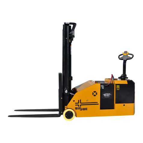
Big Joe CB33 User manual
Big Joe
Big Joe PDI Series User manual

Big Joe
Big Joe PDS 20 User manual
Big Joe
Big Joe M22 Use and care manual
