Big Joe V Series User manual

OPERATOR’S MANUAL
Big Lift LLC
www.bigjoeforklifts.com Manual No. BL-THREE WHEEL-0214
02/17/2014
Big Lift LLC
V SERIES
THREE WHEEL
COUNTERBALANCED LIFT TRUCK

WARNING
Do not operate this truck unless you
have been authorized and trained to
do so, and have read all warnings and
instructions in Operator’s Manual and
on this truck.
Do not operate this truck until you
have checked its condition. Give spe-
cial attention to tires, horn, battery,
controller, lift system (including forks
or attachments, chains, cables and
limit switches), brakes, steering
mechanism, guards and safety
devices.
Operate truck only from designated
operating position. Never place any
part of your body into the mast struc-
ture or between the mast and the
truck. Do not carry passengers. Keep
feet clear of truck and wear foot pro-
tection.
Observe applicable traffic regulations.
Yield right of way to pedestrians. Slow
down and sound horn at cross aisles
and wherever vision is obstructed.
Start, stop, travel, steer and brake
smoothly. Slow down for turns and on
uneven or slippery surfaces that could
cause truck to slide or overturn. Use
special care when traveling without
load as the risk of overturn may be
greater.
Travel with lifting mechanism as low
as possible. Always look in direction
of travel. Keep a clear view, and when
load interferes with visibility, travel
with load trailing.
Use special care when operating on
ramps travel slowly, and do not angle
or turn. Travel with load downhill.
Do not overload truck. Check name-
plate for capacity and load center
information.
When using forks, space forks as far
apart as load will permit. Before lifting,
be sure load is centered, forks are
completely under load, and load is as
far back as possible against load
backrest.
Do not handle unstable or loosely
stacked loads. Use special care when
handling long, high or wide loads, to
avoid losing the load, striking
bystanders, or tipping the truck.
Do not handle loads which are higher
than the load backrest or load back-
rest extension unless load is secured
so that no part of it could fall back-
ward.
Elevate forks or other lifting mecha-
nism only to pick up or stack a load.
Watch out for obstructions, especially
overhead.
Do not lift personnel except on a
securely attached specially designed
work platform. USE EXTREME CARE
WHEN LIFTING PERSONNEL. Make
sure mast is vertical, place truck con-
trols in neutral and apply brakes. Lift
and lower smoothly. Remain in oper-
ating position or immediate vicinity as
long as personnel are on the work
platform. Never transport personnel
on forks or work platform.
Do not allow anyone to stand or pass
under load or lifting mechanism.
When leaving truck, neutralize travel
control, fully lower lifting mechanism
and set brake. When leaving truck
unattended, also shut off power.

1
FOREWORD
As a lift truck operator, you are
responsible for a machine that is use-
ful, powerful, and can be hazardous if
not operated as described. Your Big
Lift LLC truck may weigh more than
some cars, depending on the model.
Observing and practicing the safety
warnings in this manual cannot be
overemphasized. Just knowing the
warnings, however, is no substitute for
common sense. Focusing on the task
at hand will, in almost all cases, pre-
vent accidents. Think of the truck as
your own. In this way you will learn its
capabilities and limitations.
This manual is intended to remain
with the truck at all times as a handy
reference guide to operation. Detailed
maintenance procedures are found in
the parts and service manual for the
specific truck model, and are to be
performed only by a qualified techni-
cian. For further information on
obtaining a complete parts and ser-
vice manual, see page 22 of this man-
ual.
The operator who knows his truck will
learn to spot problems as they
develop. This is accomplished by per-
forming the Daily Checks and report-
ing any problems to the designated
authority.
TABLE OF CONTENTS
SAFETY SYMBOLS..............................................................................................2
GENERAL DESCRIPTION....................................................................................2
LOAD CAPACITY..................................................................................................4
BEFORE OPERATION..........................................................................................5
GENERAL CONTROL OPERATION.....................................................................7
INSTRUMENT PANEL.........................................................................................10
OPERATION........................................................................................................12
Preparing for Operation........................................................................12
During Brake-in. ....................................................................................12
Starting the Truck..................................................................................12
Driving and Stopping Procedures.......................................................12
Loading and Unloading. .......................................................................13
Parking...................................................................................................13
Battery Charging...................................................................................14
Moving a Disabled Truck......................................................................14
NOTICE - OBTAINING A PARTS AND SERVICE MANUAL..............................22

2
SAFETY SYMBOLS
WARNING and CAUTIONS are both signal words intended to alert the viewer to
the existence and relative degree of a hazard. They are both preceded by a safety
alert symbol consisting of an exclamation mark enclosed by a triangle.
A Warning indicates a hazard which could result in injury or death if proper pre-
cautions are not taken.
A Caution indicates a reminder of routine safety practices.
A prohibition slash (circle with diagonal slash through it) indicates a procedure or
action that should not be performed under any circumstances, as both personal
injury and/or damage to equipment will result.
GENERAL DESCRIPTION
The V15 truck lifts and transports pay-
loads up to 2800 pounds on adjust-
able forks. The V18 truck lifts and
transports payloads up to 3500
pounds on adjustable forks.
The three wheel counterbalanced lift
truck has the character of a small
turning radius.
The forward and reverse motion is
controlled by a control lever on the left
side of the steering wheel. Stopping is
controlled by the brake pedal. Control
levers to the right of the operator con-
trol the Lift, Lower, and Tilt. Optional
levers are available to control side
motion of the forks and additional
attachments. The battery powered lift
truck is quiet and without exhaust
fumes.
Two front wheel mounted reversible
motors propel the lift truck in forward
or reverse direction throughout the
available speed range. The V series
lift truck can be driven with forks
raised or lowered; however, the speed
is restricted when the forks are raised
above a preset limit.
The model number will be found on
the name plate along with the serial
number, lifting capacity, and load cen-
ter.
Name Plate
R6209
COMPLIES WITH THE APPLICABLE REQUIRE-
MENTS OF ANSI B56.1 AND OSHA STANDARDS
BIG JOE LLC
WISCONSIN DELLS, WISCONSIN 53965
AUSTRALIAN PATENT NO. 537,987
U.S. PATENT NO. 4,444,284
TRUCK
TYPE
MODEL NO. SERIAL NO.
VOLTAGE
BATTERY
TYPE CERTIFIED
MAX CAP LB/ LOAD CTR IN/ LIFT HGT IN/
LOAD CTR IN/ LIFT HGT IN/ALT CAP LB/
BATTERY MIN WT LB/TRUCK WT LESS BATTERY LB/
BATTERY MAX WT LB/TRUCK WT WITH BATTERY LB/
KG MM MM
MM MMKG
KGKG
KGKG

3
This truck is equipped with a battery. Read and observe the warning decal located
near the battery. An example is shown here:
WARNING:

4
LOAD CAPACITY
Do not overload the truck. Check
capacity plate for load weight and load
center information. The standard load
center is 24”
The load capacity depends on the
load center. The load maximum
capacity listed on the capacity plate
assumes a uniform load whose center
is at 1/2 the length of the fork and cen-
tered between the forks. The maxi-
mum load capacity is reduced when
the load center exceeds 1/2 the length
of the forks or is not centered between
the forks. The fork length and wheel-
base must be adequate for the skid or
bin to be handled.
Note that a truck undergoing speed
changes is less stable than a standing
truck. If you are not sure that the truck
can lift a certain load, consult your
supervisor or the designated authority.
Load Center
R3814

5
BEFORE OPERATION
The table on page 6 covers important
inspection points on trucks which
should be checked prior to operation.
Depending on use, some trucks may
require additional checks.
The illustration below shows a sample
format for an Operator Checklist,
which can be modified as necessary
to fit your operation.
Periodic maintenance of this
truck by a QUALIFIED TECH-
NICIAN is required.
A QUALIFIED SERVICE
TECHNICIAN should check the
truck monthly for proper lubri-
cation, proper fluid levels,
brake maintenance, motor
maintenance and other areas
specified in the parts and ser-
vice manual maintenance sec-
tion.
If the truck is found to be
unsafe and in need of repair, or
contributes to an unsafe condi-
tion, make sure to immobilize
the truck so that it can not be
operated and report it immedi-
ately to the designated author-
ity. Do not operate it until it has
been restored to a safe operat-
ing condition. Do not make any
unauthorized repairs or adjust-
ments. All service must be per-
formed by a qualified
maintenance technician.
Sample of Operator Check List
WARNING:
WARNING:
WARNING:
Electric Truck
Daily Operator Check-Off List
Date
Big Joe ManufacturingCompany
Operator
Truck No. Model No.
Dept.
Check
Tires
Load Wheels
Horn
Lift Lower Control
Need MaintenanceO.K. ( )
Shift
Hour Meter
Reading Drive Hoist
Attachment Operation
Forward & Reverse Controls
Steering
Electrical Brakes
Hydraulic Leaks, Cylinders,
Valves, Hoses, Etc.
R6235

6
Operator Checks
ITEM PROCEDURE
Transmission and hydraulic
systems Check for signs of fluid leakage.
Forks and fork pins Check for cracks and damage or uneven
forks; be sure they are properly secured and
fork pins secure the forks.
Chains, cables and hoses Check that they are in place, secured cor-
rectly, functioning properly and free of binding
or damage.
Guards and load backrest Check that safety guards are in place, prop-
erly secured and not damaged
Warning Labels Check that warning labels, nameplate, etc.,
are in good condition and legible.
Horn Check that horn sounds when operated.
Steering Check for binding or looseness when steering.
Travel controls Check that the accelerator operates in all
speed ranges in forward and reverse.
Tires Check front drive wheel and steer wheel for
cracks or damage. Move truck to check that
the steer wheel can rotate freely.
Hydraulic controls Check operation of lift, tilt and side shift to
their maximum positions.
Parking brake Check that the parking brake lever engages
and disengages the brakes.
Tilt steering column Check that the tilt steering column can be
adjusted and locked in place.
Emergency stop switch Check that emergency stop switch can be dis-
engaged and reengaged.
Battery indicator Check that the instrument panel battery indi-
cator is functional.

7
GENERAL CONTROL OPERATION
Refer to the following illustration for
the location of the controls.
Control Handle
R6906

8
PARKING BRAKE
Pull up on the parking brake lever (1)
to apply brakes on the front wheels.
To release, press the button on the
lever and move the lever forward.
SHIFT LEVER
The shift lever (2) controls forward,
neutral and reverse travel.
BRAKE PEDAL
Press the brake pedal (3) to slow or
stop. The brake light will come on
when pedal is depressed.
ACCELERATOR PEDAL
As the accelerator pedal (4) is slowly
pressed, the drive motors start turning
and the truck will start to move.
According to the force applied to the
pedal, the speed increases.
STEERING WHEEL
The steering wheel (5) is operated in
the conventional manner. The rear
wheels steer the truck causing the
rear of the truck to swing out when a
turn is made.
TURN SIGNAL/LIGHT SWITCH
This combined light switch (6) oper-
ates the turn signals and the front
lights.
Turn Signal
Move the lever (6) forward to indicate
a left turn or back to indicate a right
turn.
NOTE: The lever does not automati-
cally return to the neutral
position. Reset it by hand.
Light Switch
The light switch (6) has two positions.
First position is for low lamp only. The
second position is for both the low
lamp and high lamp.
KEY SWITCH
The key switch (7) has two positions,
ON and OFF. Be sure the shift lever is
in the neutral position and the acceler-
ation pedal is released before the key
switch is turned on.
Removing the key prevents the truck
from being used by unauthorized per-
sonnel.
NOTE: If the shift lever is not in neu-
tral or the acceleration pedal
is depressed, an error code
may appear on display (10).
When the correct procedure
is used, the error code
should disappear.
STEERING COLUMN TILT LEVER
This lever (8) is used to adjust the
steering column to suit individual
operators. Move the lever () counter-
clockwise and adjust the steering col-
umn. Then move the lever clockwise
to lock the column in place.
Steering Column Tilt Lever
R6908

9
CAUTION LIGHT SWITCH
Use switch (9) to turn on the caution
light.
INSTRUMENT PANEL
The instrument panel (10) contains
various displays and controls. Refer to
Page 10.
AUXILIARY CONTROL LEVER
If equipped, the function of this lever
(11) depends on the auxiliary attach-
ment.
SIDE SHIFT CONTROL LEVER
If equipped, this lever (12) is used to
side shift the forks. The speed of the
side shift can be controlled by the
pressure on the lever.
TILT CONTROL LEVER
This lever (13) is used to tilt the mast.
Pulling the lever back will tilt the mast
backwards. Pushing it forward will tilt
the mast forward. The speed of the tilt
can be controlled by the pressure on
the lever.
LIFT CONTROL LEVER
This lever (14) is used to lift the forks.
Pulling the lever back will raise the
forks. Pushing it forward will lower the
forks. The speed of the tilt can be con-
trolled by the pressure on the lever.
Motor speed or accelerator pedal has
not affect the lowering speed.
EMERGENCY DISCONNECT
SWITCH
This switch (15) is used to cut off the
main power to the truck in case of an
emergency
SEAT ADJUSTMENT.
Before operating the truck, adjust the
operator’s seat and make sure it is
securely locked. The seat is unlocked
by turning adjusting lock (2) counter-
clockwise. Lever (1) is used to adjust
the lean of the seat. Lever (3) is used
to adjust the position of the seat.
Seat Adjustment
R6977

10
INSTRUMENT PANEL
The instrument panel (10) contains
the following displays and controls: Refer to the following illustration for
the location of the displays and con-
trols.
Instrument Panel
DISPLAY LED
When the key switch is turned on, the
system will self-diagnose and the LED
display (7) will display battery capac-
ity. A blank LED display indicates a
dead battery. The battery should be
charged when the low battery warning
indicator is on. Notify your supervisor
or proper authority.
When traveling, the LED display will
display the truck speed.
When an internal fault occurs, the
LED display will show a fault code.
Notify your supervisor or proper
authority.
R6909

11
LED INDICATORS
There are six indicators:
CONTROL BUTTONS
There are six control buttons :
1. Power Indicator: Indi-
cates power supply is
OK.
2. Error Indicator: Indi-
cates improper opera-
tion.
3. Low Battery Warning:
Indicates battery capac-
ity is lower than 20% and
a buzzer sounds.
4. Parking Brake Warn-
ing: Indicates controller
temperature is out of
range.
5. Parking Brake Indica-
tor: Indicates parking
brake is engaged.
6. Seat Belt Indicator:
Indicates the seat belt is
not secured.
A. Enter Button: Used to
enter changes.
B. Roll Up Button: Used
to change highlighted
digit on the instrument
panel display.
C. Roll Down Button:
Used to change high-
lighted digit on the instru-
ment panel display.
D. Set Up Button: Used
to shift the highlight to
the previous digit on the
instrument panel display.
E. Set Down Button:
Used to shift the high-
light to the following digit
on the instrument panel
display.
F. Out Button: Used to
cancel changes.

12
OPERATION
PREPARING FOR OPERATION.
Preparing the truck for operation after
delivery or transport:
1. Check that the equipment is com-
plete.
2. Check the hydraulic oil level.
3. Charge the batteries. Refer to
page 14.
4. Visually inspect the entire truck
(in particularly wheels and forks)
for obvious damage.
DURING BRAKE-IN.
Operating the truck under light load
conditions is recommended. Limited
load is 70 to 80% of the rated load.
During the first 100 hours of operation
observe the following:
1. Prevent the new batteries from
over-discharging.
2. Perform preventive maintenance
services carefully and completely.
3. Avoid sudden stops, starts or
turns.
4. Perform oil changes and lubrica-
tion earlier than specified.
STARTING THE TRUCK.
1. Place the shift lever in neutral.
2. Hold the steering wheel with the
left hand and turn on key switch
with the right hand.
3. Slightly lift and tilt the forks.
4. Press the brake pedal and
release the parking brake.
DRIVING AND STOPPING PROCE-
DURES
Travel.
1. Place the shift lever in forward or
reverse.
2. Slowly step on the accelerator
pedal until the desired speed is
obtained.
WARNING: Do not step on the
accelerator pedal and
the brake pedal at the
same time.
Decreasing Speed.
1. Slowly release the accelerator
pedal. The truck will decelerate.
Steering.
The steer wheels are located at the
rear of the truck causing the rear to
swing out when turning. Slow down
and move toward the side being
turned.
Stopping and Parking.
1. Slow down and press the brake
pedal to stop the truck.
2. Place the shift lever in neutral.
3. Apply the parking brake.
4. Tilt the forks until parallel with the
floor.
5. Lower the forks to the ground.
6. Turn off the key switch and
remove the key.

13
LOADING AND UNLOADING.
1. Place the truck in front of the
load.
2. Adjust the forks sideways to
maintain proper balance of the
load.
3. The pallet should be evenly posi-
tioned across both forks.
4. Insert the forks into the pallet a
far as possible.
5. To raise the load from the ground:
a. Slightly lift the load.
b. Be sure the load is stable.
c. Tilt the forks back to level the
load.
6. When handling bulky loads which
restrict your vision, operate the
truck in reverse except when
climbing grades.
Stacking.
1. Slowly approach the load area.
2. Stop the truck right in front of the
load.
3. Check the condition of the load.
4. Tilt the mast forward until forks
are horizontal.
5. Raise the forks until they are a lit-
tle higher than the load.
6. Move forward to place the load
directly over the desired area and
stop the truck.
7. Make sure you load is just over
the desired area and slowly lower
the load into position. Make sure
the load is securely stacked.
8. Lower forks from the load using
necessary lift and tilt operation
and then back the truck up.
9. After making sure the fork tips are
clear of the load, lower the forks
and tilt backwards.
Un-stacking.
1. Slowly approach the load to be
retrieved.
2. Stop the truck is right in front of
the load.
3. Check the condition of the load.
4. Tilt the mast forward until forks
are horizontal.
5. Raise the forks up to the position
of the pallet or skid.
6. Make sure the forks are posi-
tioned properly for the pallet.
Slowly move forward to insert the
forks into the pallet as far as pos-
sible and then stop the truck.
7. Check around the truck to insure
that the path of travel is unob-
structed and back away slowly.
8. Lower the forks and tilt back-
wards.
PARKING.
When finished with moving loads,
return the truck to its maintenance or
storage area. Turn off the key switch.
Charge batteries as necessary. Refer
to battery care instructions, page 14.
.

14
BATTERY CHARGING
Refer to DOC 245 for battery safety
and maintenance.
NOTE: Battery charging instructions
are contained in the service
manual.
MOVING A DISABLED TRUCK
Do not attempt to move a disabled
truck; notify your supervisor or proper
authority.

15
The following operating instructions appear on the truck warning decal, which is
located near the steering arm.
Do not operate this truck
unless you have been trained
and authorized to do so, and
have read and understand all
warnings and instructions
contained in this operator’s
manual and on this truck.
R7094
R7075
Do not operate this
truck until you have
checked its condition.
Give special attention
to tires, horn, battery,
lift system (including
forks or attachments,
chains, cables and limit
switches), brakes,
steering mechanism,
guards and safety
devices. If you have
any questions, notify
your supervisor or
proper authority.

16
R7096
Operate truck only from desig-
nated operating position. Never
place any part of your body into
the mast structure or between
the mast and the truck. Do not
carry passengers. Keep feet
clear of truck and wear foot pro-
tection.
R7097
Observe applicable traffic
regulations. Yield right of
way to pedestrians. slow
down and sound horn at
cross aisles and wherever
vision is obstructed.

17
R7098
Travel with lifting mechanism
as low as possible. Always look
in direction of travel. Keep a
clear view, and when load inter-
feres with visibility, travel with
load trailing.
R7101
When using forks,
space forks as far apart
as load will permit.
Before lifting, be sure
load is centered, forks
are completely under
the load, and load is as
far back as possible
against the load back-
rest.

18
Do not handle loads which are higher than the
load backrest or load backrest extension unless
load is secured so that no part of it could fall
backward.
R7103
Elevate forks or other lifting mechanism
only to pick up or stack a load. Watch out
for obstructions, especially overhead.
R7102
This manual suits for next models
2
Table of contents
Other Big Joe Forklift manuals

Big Joe
Big Joe PDS 20 User manual

Big Joe
Big Joe PPT 45 Series Use and care manual
Big Joe
Big Joe T15 User manual
Big Joe
Big Joe PDSR User manual
Big Joe
Big Joe E30 User manual
Big Joe
Big Joe M22 Use and care manual
Big Joe
Big Joe EZ30 Use and care manual
Big Joe
Big Joe PDI Series User manual
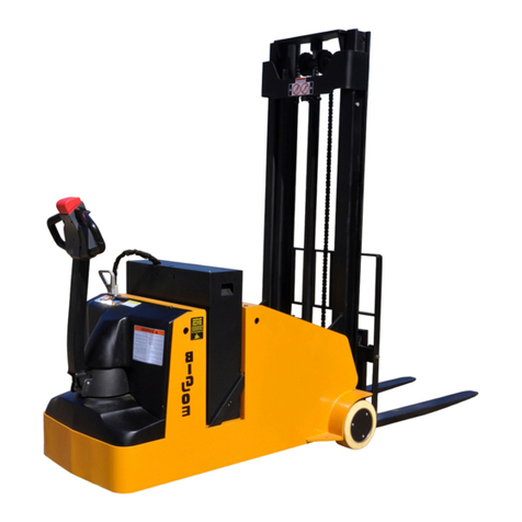
Big Joe
Big Joe CB22 User manual
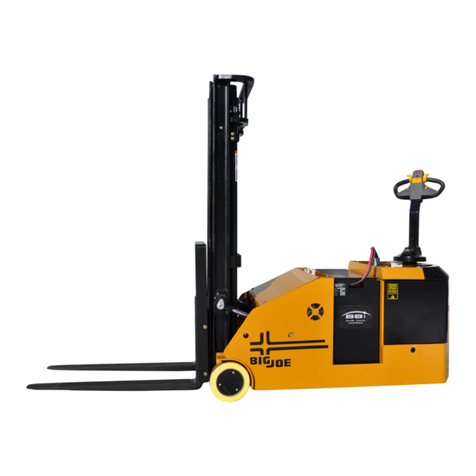
Big Joe
Big Joe CB33 User manual
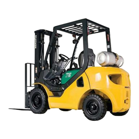
Popular Forklift manuals by other brands

Presto Lifts
Presto Lifts Power Stak PPS2200-150AS Installation, operation and service manual
kleenconnect
kleenconnect LNI2-233 Installation and operation manual
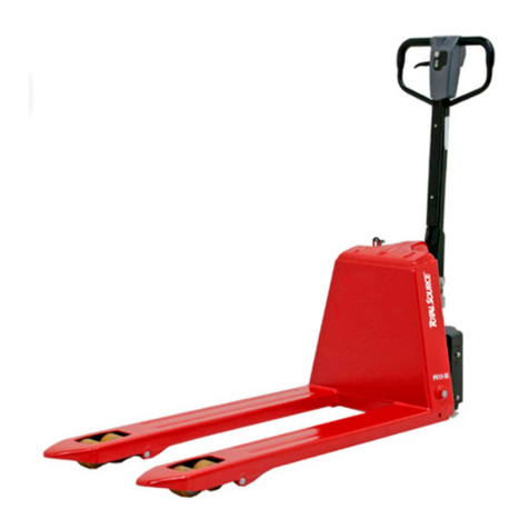
Total Source
Total Source ELP15EULIT operating manual
Hyster
Hyster H135FT Service & repair manual

Still
Still RCD15 Original instructions

EKKO
EKKO EB20E specification
