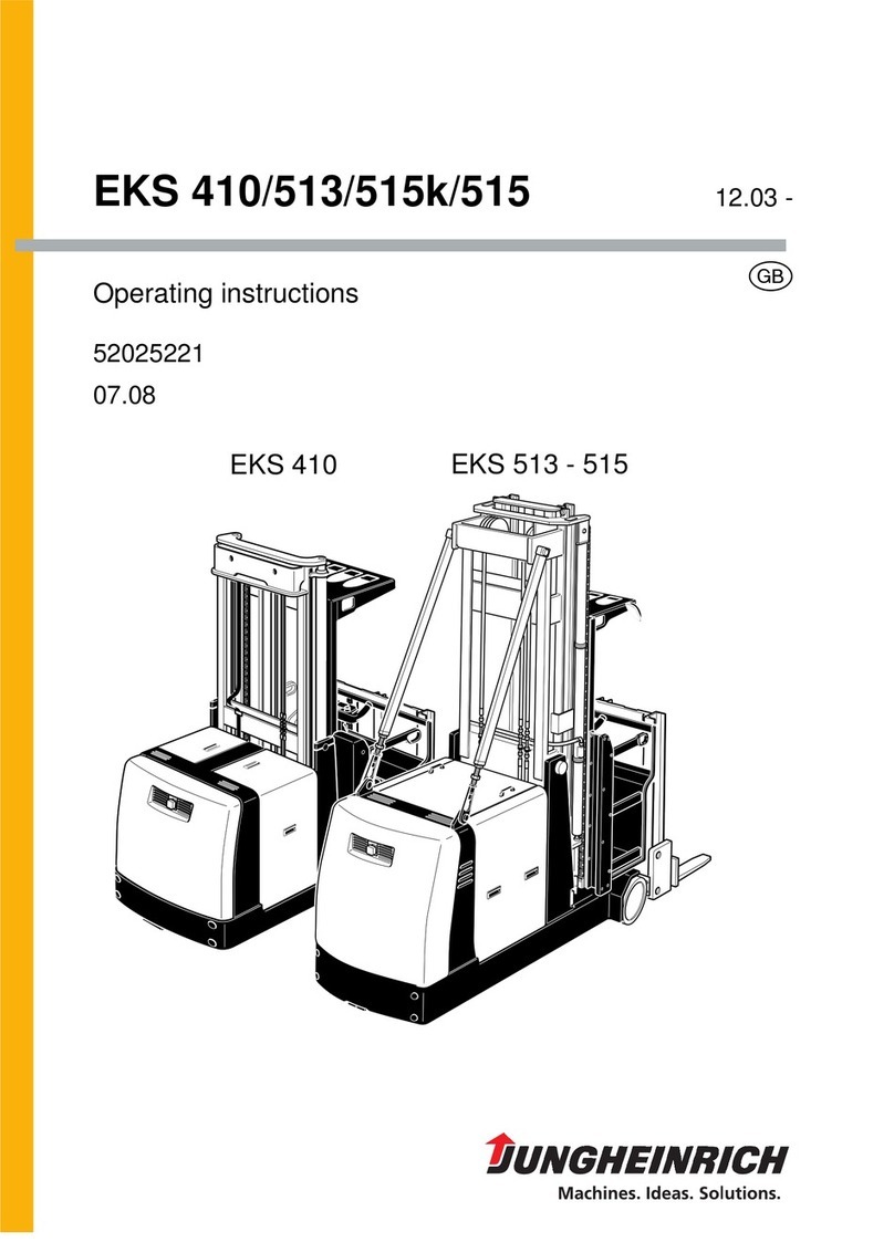
Big Joe M22 Use and care manual

Big Lift LLC MANUAL NO. BL-M22EP-0119 - 01-11-2019
www.bigjoeforklifts.com
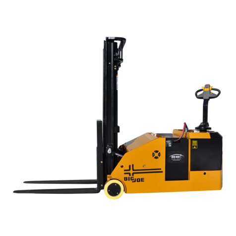
M22
MANUALLY PROPELLED,
SEMI-ELECTRIC LIFT TRUCK
Used from Serial Number 326100281
Operation
Maintenance
Repair Parts List

BL-M22EP-0119 - 01-11-2019
WARNING
Do not operate this truck unless you have been autho-
rized and trained to do so, and have read all warnings
and instructions in Operator’s Manual and on this
truck.
Do not operate this truck until you have checked its
condition. Give special attention to wheels, battery, lift
system (including forks or attachments, chains, and
cables), brake, steering mechanism, guards and
safety devices.
Operate truck only from designated operating position.
Never place any part of your body into the mast struc-
ture or between the mast and the truck. Do not carry
passengers. Keep feet clear of truck and wear foot
protection.
Observe applicable traffic regulations. Yield right of
way to pedestrians. Slow down at cross aisles and
wherever vision is obstructed.
Start, stop, travel, steer and brake smoothly. Slow
down for turns and on uneven or slippery surfaces that
could cause truck to slide or overturn. Use special
care when traveling without load as the risk of overturn
may be greater.
Travel with lifting mechanism as low as possible.
Always look in direction of travel. Keep a clear view,
and when load interferes with visibility, travel with load
trailing.
Use special care when operating on ramps travel
slowly, and do not angle or turn. Travel with load
downhill.
Do not overload truck. Check nameplate for capacity
and load center information.
When using forks, space forks as far apart as load will
permit. Before lifting, be sure load is centered, forks
are completely under load, and load is as far back as
possible against load backrest.
Do not handle unstable or loosely stacked loads. Use
special care when handling long, high or wide loads, to
avoid losing the load, striking bystanders, or tipping
the truck.
Do not handle loads which are higher than the load
backrest unless load is secured so that no part of it
could fall backward.
Elevate forks or other lifting mechanism only to pick up
or stack a load. Watch out for obstructions, especially
overhead.
Do not allow anyone to stand or pass under load or lift-
ing mechanism.
When leaving truck, neutralize travel control, fully
lower lifting mechanism and set brake. When leaving
truck unattended, also shut off power.

TABLE OF CONTENTS
BL-M22EP-0119 - 01-11-2019 I
Section Page Section Page
DESCRIPTION............................................................1-1
1-1 INTRODUCTION................................................1-1
1-2 GENERAL DESCRIPTION.................................1-1
1-3 SAFETY FEATURES..........................................1-1
OPERATION ...............................................................2-1
2-1 GENERAL...........................................................2-1
2-2 OPERATING PRECAUTIONS............................2-1
2-3 BEFORE OPERATION.......................................2-1
2-4 INSTRUMENTS AND CONTROLS....................2-3
2-4.1 INSTRUMENT PANEL...............................2-3
2-4.2 FOOT ACTUATED FLOOR LOCK.............2-3
2-4.3 OPERATOR HANDLE ...............................2-3
2-5 TRANSPORT......................................................2-3
2-5.1 MOVING, POSITIONING, STOPPING ......2-3
2-5.2 TURNING...................................................2-4
2-6 OPERATING THE LIFT......................................2-4
2-7 LOADING AND UNLOADING.............................2-4
2-8 PARKING............................................................2-4
PLANNED MAINTENANCE ........................................3-1
3-1 GENERAL...........................................................3-1
3-2 MONTHLY AND QUARTERLY CHECKS...........3-1
3-3 BATTERY CARE................................................3-1
3-3.1 GENERAL..................................................3-1
3-3.2 SAFETY RULES........................................3-2
3-3.3 BATTERY CARE AND CHARGING...........3-2
3-4 CHARGING BATTERIES ...................................3-2
3-4.1 BATTERY CHARGER INDICATORS ........3-2
3-4.2 CHARGING................................................3-2
3-5 LUBRICATION....................................................3-2
3-6 LIFT CHAIN MAINTENANCE.............................3-2
TROUBLESHOOTING ................................................4-1
4-1 GENERAL...........................................................4-1
LIFT SYSTEM SERVICING........................................ 5-1
5-1 GENERAL.......................................................... 5-1
5-2 LIFT CHAIN WEAR INSPECTION..................... 5-1
5-3 LIFT CHAINS ADJUSTMENT............................ 5-1
5-4 LIFT CHAINS REPLACEMENT......................... 5-1
5-5 LIFT FORKS ...................................................... 5-3
5-5.1 REMOVAL................................................. 5-3
5-5.2 INSTALLATION......................................... 5-3
5-6 LIFT CARRIAGE................................................ 5-3
5-7 LIFT CYLINDER (SINGLE STAGE)................... 5-4
5-7.1 REMOVAL................................................. 5-4
5-7.2 INSTALLATION......................................... 5-4
5-8 LIFT CYLINDER (TELESCOPIC) ...................... 5-5
5-8.1 REMOVAL................................................. 5-5
5-8.2 INSTALLATION......................................... 5-5
HYDRAULIC SYSTEM SERVICING........................... 6-1
6-1 HYDRAULIC PUMP ASSEMBLY....................... 6-1
6-1.1 REMOVAL................................................. 6-1
6-1.2 INSTALLATION......................................... 6-1
6-2 LIFT CYLINDER................................................. 6-2
ELECTRICAL SYSTEM SERVICING......................... 7-1
7-1 HYDRAULIC PUMP MOTOR............................. 7-1
7-2 BATTERY CHARGER........................................ 7-1
FRAME AND RELATED PARTS SERVICING ........... 8-1
8-1 GENERAL.......................................................... 8-1
8-2 LOAD WHEEL REPLACEMENT........................ 8-1
8-3 CASTER WHEEL REPLACEMENT................... 8-1
8-4 FOOT ACTUATED FLOOR LOCK..................... 8-1
ILLUSTRATED PARTS BREAKDOWN...................... 9-1

II BL-M22EP-0119 - 01-11-2019
NOTES

BL-M22EP-0119 - 01-11-2019 1-1
SECTION 1
DESCRIPTION
1-1. INTRODUCTION.
This publication describes the 12 volt M22 lift truck
distributed by Big Lift LLC. Included are operating
instructions, planned maintenance instructions, lubri-
cation procedures, corrective maintenance procedures
and a complete parts list with part location illustrations.
Users shall comply with all requirements indicated in
applicable OSHA standards and current edition of
A.N.S.I. B56.1 Part II. By following these requirements
and the recommendations contained in this manual,
you will receive many years of dependable service
from your M22 lift truck.
1-2. GENERAL DESCRIPTION.
The manually-propelled M22 truck, Figure 1-2, lifts and
transports payloads up to 2200 pounds on adjustable
forks.
The handle is used to control the lift truck. The control
handle is used to propel and steer the lift truck. Lift
and Lower are controlled by a lever located near the
operator.
The model number will be found on the name plate
(Figure 1-1) along with the serial number, lifting capac-
ity, and load center. Figure 1-2 shows the locations of
the truck’s main components and controls.
1-3. SAFETY FEATURES.
The M22 is designed and engineered to provide maxi-
mum safety for operator and payload. Some of the
safety features incorporated into the design are:
Figure 1-1 Name Plate
• Foot actuated floor lock.
• Positive steer tracking caster.
• Lift control automatically returns to “OFF” when
released.
• High visibility color scheme of truck provides visual
alert of truck’s presence.
• Battery Discharge Indicator (BDI).
• Key switch.
R8352

1-2 BL-M22EP-0119 - 01-11-2019
Figure 1-2. M22 Lift Truck
R3851
Pos. # Description Pos. # Description
1 Handle 8 Frame / Mast
2 Battery Charger Cord 9 Lift Cylinder
3 Pump and Motor Assembly 10 Lift / Lower Lever
4 Cover 11 Battery Discharge Indicator (BDI)
5 Foot Actuated Floor Lock 12 Emergency Stop Switch
6 Casters 13 Adjustable Forks
7 Battery 14 Adjustable Straddle Legs

BL-M22EP-0119 - 01-11-2019 2-1
SECTION 2
OPERATION
2-1. GENERAL.
The following paragraphs describe the controls and
various procedures involved in proper operation of the
lift truck.
2-2. OPERATING PRECAUTIONS.
WARNING: Improper operation of the lift truck may
result in operator injury, or load and/or lift
truck damage. Observe the following
precautions when operating the M22 lift
truck.
The following safety precautions must be adhered to
at all times.
1. Turn off the key switch and remove the key when
leaving the lift truck.
2. Leave the load in the full down position for over-
night storage.
3. Engage the floor lock before leaving the lift truck.
4. Center the load as far as possible toward the
backrest. Never lift a load on the fork tips or on
one fork blade.
5. Do not attempt to lift a load heavier than the rated
capacity of the truck. Check that the center of
gravity of the load is not beyond the load center
listed on the name plate (Figure 1-1). See Figure
2-1 for an explanation of load center.
6. Check for obstructions before raising or lowering
a load.
7. Lower the load before traveling. If it is necessary
to move the load while raised, travel cautiously
and use extra care when turning.
2-3. BEFORE OPERATION.
Table 2-1 covers important inspection points on the
M22 lift truck which should be checked prior to opera-
tion. Depending on use some trucks may require addi-
tional checks.
Figure 2-2 shows a sample format for an Operator
Checklist, which can be modified as necessary to fit
your operation.
WARNING: Periodic maintenance of this truck by a
QUALIFIED SERVICE TECHNICIAN is
required.
CAUTION: A QUALIFIED SERVICE TECHNICIAN
should check the truck monthly for
proper lubrication, proper fluid levels,
brake maintenance, motor maintenance
and other areas specified in the SEC-
TION 3.
WARNING: If the truck is found to be unsafe and in
need of repair, or contributes to an
unsafe condition, report it immediately to
the designated authority. Do not operate
it until it has been restored to a safe
operating condition. Do not make any
unauthorized repairs or adjustments. All
service must be performed by a qualified
service technician.
Figure 2-1 Load Center
R3814

2-2 BL-M22EP-0119 - 01-11-2019
Table 2-1 Operator Checks
Figure 2-2 Sample of Operator Check List
ITEM PROCEDURE
Hydraulic System Check for signs of fluid leakage.
Forks Check for cracks and damage and that they are properly secured.
Chains, cables and hoses Check that they are in place, properly secured and not damaged.
Guards Check that safety guards are in place, properly secured and not damaged.
Safety signs Check that warning labels, nameplates, etc., are in good condition and legible.
Wheels Check wheels for cracks or damage. Move the truck to check load wheel and cast-
ers for freedom of rotation.
Lift and Lower Check operation of lift and lower to their maximum positions.
Floor Lock Check that the floor lock holds the truck stationary.
Lift Motor Check for grinding or laboring sounds.
R6734

BL-M22EP-0119 - 01-11-2019 2-3
2-4. INSTRUMENTS AND CONTROLS.
2-4.1. Instrument Panel
The instrument panel contains the lift/lower control
lever, battery discharge indicator (BDI) and the emer-
gency stop switch.
2-4.2. Foot Actuated Floor Lock
The foot actuated floor lock is used to hold the truck
stationary.
2-4.3. Operator Handle
The operator handle located on the mast is used to
propel and steer the lift truck.
Figure 2-3. M22 Lift Truck
2-5. TRANSPORT.
2-5.1. Moving, Positioning and Stopping
1. Check that the load is in the down position before
traveling.
2. Release the floor lock by pressing the Floor Lock
Release Pedal.
3. Apply pressure to the operator handle to move
the truck forward. Lower the operator handle so
that you are further away from the truck and move
the truck in reverse.
4. To stop the lift truck, hand pressure against the
operator handle is usually adequate.
5. After the lift truck has stopped, always engage the
floor lock before lifting or lowering and when park-
ing.
R8354
R8355
R8356

2-4 BL-M22EP-0119 - 01-11-2019
2-5.2. Turning
1. Release the floor lock.
NOTE: Turning and maneuvering the lift truck is
made easier if the truck is in motion.
2. Begin rolling the truck and simultaneously apply
side pressure to the handle to cause the caster
wheels to swivel.
2-6. OPERATING THE LIFT.
WARNING: Check the space above the load on the
forks to ensure that the load will not
strike any obstruction while being raised
and make sure that it’s not heavier than
the trucks capacity.
1. Turn on the truck.
2. To raise the forks, pull the lift control back and
hold until the forks reach the desired height. The
forks will raise at a fixed speed. Return the lift
control to the neutral position.
3. To lower the forks, push the lift control forward
and hold until the forks reach the desired level.
The lowering speed can be controlled by the
lever. Return the lift control to the neutral position.
2-7. LOADING AND UNLOADING.
1. Move the truck to the location where the load is to
be picked up.
2. Adjust the forks to the maximum practical width to
support the load.
3. Raise the forks to the desired height for entry
under the load.
4. Move the lift truck into position so that the forks
are centered under the load.
5. Move the lift truck forward to place the load as far
back as possible toward the lift carriage. Raise
the forks to lift the load.
CAUTION: To avoid spilling the load, move slowly
and use extra caution when turning.
6. Reverse the truck from the loading position.
7. When the load is clear of its rack, lower the load,
leaving enough floor clearance to maneuver the
truck.
8. Push or pull the truck carefully to the area where
the load is to be placed.
9. Align the lift truck with its new position.
10. Raise the forks to the desired height and slowly
move the lift truck into position for off-loading.
CAUTION: The load must rest squarely on its rack
when it is lowered into position.
11. When the load is in position, lower the forks until
the pallet rest on its rack and the forks are free.
12. Slowly move the lift truck in reverse checking that
the forks do not catch on the pallet or rack.
13. Lower the forks when they are clear from the rack.
14. Proceed to move the next load.
2-8. PARKING.
When finished with moving loads, lower the forks and
move the lift truck to its maintenance or storage area.
Engage the floor lock and make sure the operator han-
dle is secured in an upright position. Turn off the truck
and charge the battery if required. Refer to battery
care instruction in SECTION 3.

BL-M22EP-0119 - 01-11-2019 3-1
SECTION 3
PLANNED MAINTENANCE
3-1. GENERAL.
Planned maintenance consists of periodic visual and
operational checks, parts inspection, lubrication, and
scheduled maintenance designed to prevent or dis-
cover malfunctions and defective parts. The operator
performs the checks in SECTION 2, and refers any
required servicing to a qualified service Technician
who performs the scheduled maintenance and any
required servicing.
3-2. MONTHLY AND QUARTERLY CHECKS.
Table 3-1 is a monthly and quarterly inspection and
service chart based on normal usage of equipment
eight hours per day, five days per week. If the lift truck
is used in excess of forty hours per week, the fre-
quency of inspection and service should be increased
accordingly. These procedures must be performed by
a qualified service technician or your Big Lift LLC Ser-
vice Representative.
3-3. BATTERY CARE.
3-3.1. General
The care and maintenance of the battery is very
important to obtain efficient truck operation and maxi-
mum battery life.
Leakage voltage from battery terminals to battery case
can cause misleading trouble symptoms with the
truck’s electrical system. Since components of the
truck’s electrical system are insulated from truck
frame, leakage voltage will not normally affect truck
operation unless a short circuit or breakdown of circuit
wire insulation to truck frame occurs.
A voltage check from battery connector terminal to
battery case should indicate near zero volts. Typically,
however, the sum of the voltages at both terminals will
equal battery volts. This leakage voltage will discharge
the battery. As battery cleanliness deteriorates, the
usable charge of the battery decreases due to this self
discharge.
Although a leakage voltage reading of zero volts may
not be possible, a cleaner battery will have more
usable charge for truck operation and not affect opera-
tion of electronic devices on the unit.
Table 3-1Monthly and Quarterly Inspection and Service Chart
VISUAL CHECKS
INTERVAL INSPECTION OR SERVICE
Daily Check battery condition. Check cables for good contact with terminal posts.
Daily Observe performance of truck. Check any improper operation.
Weekly Check floor lock.
Monthly Inspect hoses and fittings for leaks.
Monthly Check wiring for loose connections and damaged insulation.
Monthly Check load wheels for wear.
Monthly Check caster wheels for wear.
Monthly Check lift chain tension, lubrication & operation (see paragraph 3-6.)
Quarterly Check lift cylinder for leakage.
Semi-annually Inspect for chain wear (See SECTION 8)

3-2 BL-M22EP-0119 - 01-11-2019
3-3.2. Safety Rules
• Do not lay metallic or conductive objects on battery.
Arcing will result.
• Do not touch non-insulated parts of DC output con-
nector or battery terminals to avoid possible electri-
cal shock.
• Do not charge a frozen battery.
3-3.3. Battery Care and Charging
1. Charge the battery only in areas designated for
that use.
2. Battery terminals should be checked and cleaned
of corrosion regularly. Good battery terminal con-
tact is essential not only for operation, but also for
proper charging of the battery.
3. The charging requirements will vary depending on
the use of the truck.
4. Make certain battery used meets weight and size
requirements of truck. NEVER operate truck with
an undersized battery.
3-4. CHARGING BATTERIES
3-4.1. Battery Charger Indicators
The battery charger is fully automatic.
The LED indicator on the dashboard indicate battery
charging status. Red indicates charging in progress.
Yellow indicates charging error, for example charger
not plugged in correctly. Green indicates that the bat-
tery is fully charged.
3-4.2. Charging
Charging requirements will vary depending on depth of
discharge and temperature. Follow safety rules when
placing a battery on charge.
Proceed as follows:
1. Park truck at charging station with carriage low-
ered and the truck turned off.
2. Check the condition of the AC cord and battery
cables. If there are any cuts in the cable, any
exposed wires, loose plugs or connectors, DO
NOT attempt to charge the batteries. Contact
appropriate personnel for repairs to be made.
3. Connect the charger AC cord to the appropriate
power supply.
4. The Red light indicates that power is connected.
5. When the battery is fully charged the green indi-
cator will come on.
6. Unplug the power cord when finished charging.
3-5. LUBRICATION.
Refer to Table 3-2 for the recommended types of
grease and oil. Table 3-3 in conjunction with Figure 3-1
identifies the items requiring lubrication.
3-6. LIFT CHAIN MAINTENANCE.
Fully raise and lower lift carriage while observing
chains as they move over chain sheaves. Ensure
chain is aligned and tracking properly and all links are
pivoting freely. With lift carriage fully lowered, spray or
brush on a film of SAE 30 or 40 engine oil.
Table 3-2 Recommended Lubricants
(See Table 3-3 for Application)
No. 1 Grease—Lithium base, general purpose.
No. 2 Hydraulic oil-Heavy duty with a viscosity of
150 SUS foam suppressing agent and
rust and oxidation inhibitors
Hydraulic oil-Heavy duty with a viscosity of
100 SUS foam suppressing agent and
rust and oxidation inhibitors (Note)
No. 3 SAE 30 or 40 Engine lubricating oil
NOTE: USED ON COLD CONDITIONED TRUCKS

BL-M22EP-0119 - 01-11-2019 3-3
Figure 3-1 Lubrication Diagram
Table 3-3 Lubrication Chart
Table 3-4
R8357
FIG 3-2
INDEX
NO.
LOCATION METHOD OF
APPLICATION TYPE
(Table
3-3)
APPLICATION
OF
LUBRICANT
1 Lift Carriage Brush No. 1 Light coating where forks slide
2 Mast Brush No. 1 Full length ofchannelwhererollers
operate.
3 Lift Chain Brush or Spray No. 3 See Paragraph 3-6.
4 Hydraulic Reservoir
Capacity-1 quarts Can No. 2 With lift carriage fully lowered, fill
reservoir with hydraulic oil to 1
inch below opening

3-4 BL-M22EP-0119 - 01-11-2019
NOTES

BL-M22EP-0119 - 01-11-2019 4-1
SECTION 4
TROUBLESHOOTING
4-1. GENERAL
This section gives fixes for some common problems
that may arise while operating the lift truck. Table 4-1 lists these malfunctions, their causes, probable and
corrective action that will resolve the problem.
Table 4-1 Troubleshooting Chart
MALFUNCTION PROBABLE CAUSE CORRECTIVE ACTION
Oil sprays or flows from the top of
lift cylinder. Worn or Defective packing in lift
cylinder. Reseal lift cylinder by installing
new packing, seal, and wiper
ring.
Oil splashes out of vent cap when
lowering forks. Oil level too high Drain, then refill reservoir leaving
1 inch air space when forks are
in lowest position.
Squealing sound when lifting. a. Oil level low. Check and add oil as necessary.
b. Dry mast channels. Apply grease.
c. Defective mast or carriage bear-
ings. Replace bearing.
Forks do not lift to top. Oil level low. Add oil.
Oil leaks at hydraulic pump Defective pump. Replace pump assembly.
Lift control does not return to
neutral. a. Foreign particles. Clean system.
b. Defective pump. Replace pump assembly
Weak, slow or uneven action of
hydraulic system. a. Defective pump Replace pump assembly
b. Defective lift cylinder Repair or replace.
c. Load exceeds capacity. See data plate.
Forks do not lift, motor does not
run a. Battery Over discharged. Check. Recharge if required.
b. Defective wiring. Check and repair as required.
c. Defective motor. Replace pump assembly.
Forks do not lift, motor runs. Defect in hydraulic system Check hydraulic oil level. Check
oil lines to lift cylinder and
repair as required.
Forks creep down with or without
load. a. Oil bypassing in pump or control
valve. Replace pump assembly.
b. Worn lift cylinder packing Replace worn parts.
c. Leak in hydraulic system. Check for leaky hose or fittings in
hydraulic system
Truck moves when floor lock is
engaged. Defective floor lock. Replace

4-2 BL-M22EP-0119 - 01-11-2019
NOTES

BL-M22EP-0119 - 01-11-2019 5-1
SECTION 5
LIFT SYSTEM SERVICING
5-1. GENERAL
This section covers maintenance and repair proce-
dures for the lift system. The lift system consists of:
Inner mast assembly
Lift carriage
Lift forks
Lift chain
The lift cylinder is considered part of the hydraulic sys-
tem and is covered in SECTION 6.
5-2. LIFT CHAIN WEAR INSPECTION.
Both lift chains should be replaced when either chain
is worn enough to increase it’s length by 3% or more.
To make this determination proceed as follows.
Using a section of chain that sees the most frequent
operation over the chain sheaves, isolate a vertical
portion under tension from the weight of carriage and
forks.
Measure the distance between pin centers on 20 verti-
cal links. If the section measures 12.88” or more, the
chain should be replaced.
New chain anchor pins should be installed when
chains are replaced. Never replace a partial section of
chain and never repair a damaged chain. Refer to
paragraph 5-4. when installing new chain.
5-3. LIFT CHAINS ADJUSTMENT.
1. Lower the carriage fully, then disconnect battery.
CAUTION: At least 3 full threads must be present
below bottom hex nut after completion of
adjustment.
2. Loosen the top jam nuts on the adjusting bolts.
WARNING: Before attempting any adjustment, make
certain power is disconnected.
3. Take up slack in both chains by turning the bottom
nuts on adjusting bolts. Try to get equal tension
on both chains.
4. Align adjusting bolts so that they are parallel to
the mast.
5. Tighten the jam nuts while maintaining alignment
of the adjusting bolts.
5-4. LIFT CHAINS REPLACEMENT.
1. Place a solid support on the floor under the verti-
cal members nearest the center of the lift car-
riage.
2. Lower the carriage until it is supported by the sup-
port and the chains are slack, then disconnect
battery.
WARNING: Before attempting any adjustment, make
certain power is disconnected.
3. Remove cotter pin and clevis pin that secure
chain to the lift carriage.
4. Remove cotter pin and clevis pin that secure
chain to adjusting bolt.
5. Remove the chain from sheave.
6. Position new chain in place on sheave.
7. Connect chain to adjusting bolt with clevis pin and
cotter pin.
8. Connect the opposite end of chain to the lift car-
riage with clevis pin and cotter pin.
9. Replace the remaining chain is the same manner.
10. Adjust chains according to paragraph 5-3.

5-2 BL-M22EP-0119 - 01-11-2019
Figure 5-1. Lift Chain
DY_0013

BL-M22EP-0119 - 01-11-2019 5-3
5-5. FORKS.
Check the forks periodically for cracks and other dam-
age.
5-5.1. Removal
CAUTION: The forks are very heavy and we do not
recommend doing this by yourself.
1. Pull up the fork pin and slide the fork to the open
slot in the bottom and center of the fork carriage.
2. Once in the center in front of the slot tilt the fork
up and while supporting the fork, lift the fork off
the carriage.
3. Repeat step 1 and 2 with the second fork.
5-5.2. Installation
CAUTION: The forks are very heavy and we do not
recommend doing this by yourself.
1. Lift the fork and position the fork at the open slot
in the bottom and center of the fork carriage.
2. Pull up the fork pin and slide the fork to the
desired position and then let go of the fork pin.
3. Repeat step 1 and 2 with the second fork.
5-6. LIFT CARRIAGE.
1. Completely lower the carriage until the chains are
slack, then disconnect battery.
2. Remove the lift chains as described in paragraph
5-4.
3. Using a suitable lifting device attached to the lift
carriage, slowly raise the carriage out of the mast.
4. Remove snap ring and then remove the roller.
5. Repeat step 4 for all rollers on the carriage.
6. Install the lift carriage in the reverse order of
removal.
Figure 5-2 lift Carriage
R8358

5-4 BL-M22EP-0119 - 01-11-2019
5-7. LIFT CYLINDER (SINGLE STAGE).
5-7.1. Removal
1. Chock all wheels and engage the floor lock.
2. Raise the forks approximately three feet from the
floor and position blocks or other strong supports
under the lift carriage. Keep supports in place
during the entire procedure.
3. Lower the carriage onto the supports. Check that
the supports are supporting the carriage.
WARNING: Before attempting any repair, make cer-
tainpowerisdisconnectedbydisconnect-
ing the battery.
WARNING: Before disconnecting any hydraulic lines,
check that the system is not under pres-
sure.
4. Remove return hose from the top of cylinder.
5. Loosen pressure hose at the bottom of lift cylinder
and manually push the ram down as far as possi-
ble. The chain will become slack and need not be
removed.
6. Disconnect pressure hose from the bottom cylin-
der.
7. Remove connector and packing washer from cyl-
inder.
8. Lift chain from sheave and set it aside.
9. Lift ram head from cylinder.
10. Remove screws, lock washers, flat washers that
secure the lift cylinder bracket to the frame and
remove the cylinder.
5-7.2. Installation
1. Position the lift cylinder on the mast and secure
with screws, flat washers, lock washers.
2. Position ram head on the lift cylinder.
3. Position lift chain on sheave.
4. Install connector and packing washer on cylinder.
5. Connect pressure hose to the bottom of cylinder.
6. Connect return hose to the top of cylinder.
7. Fill the hydraulic reservoir. Use hydraulic oil listed
in Table 3-2.
8. Reconnect the battery and turn on the truck.
9. Operate the lift and lower to refill the cylinder and
lines with hydraulic oil.
10. Check level of hydraulic oil to bring to proper
level. Use hydraulic oil listed in Table 3-2.
11. Adjust the lift chains according to paragraph 5-3.
Figure 5-3 Lift Cylinder and Hydraulic System (Single Stage Mast)
DY_0006 DY_0003
Table of contents
Other Big Joe Forklift manuals
Big Joe
Big Joe T15 User manual
Big Joe
Big Joe CB22 User manual
Big Joe
Big Joe E30 User manual
Big Joe
Big Joe V Series User manual

Big Joe
Big Joe PPT 45 Series Use and care manual
Big Joe
Big Joe PDI Series User manual
Big Joe
Big Joe EZ30 Use and care manual

Big Joe
Big Joe PDS 20 User manual
Big Joe
Big Joe PDSR User manual
Big Joe
Big Joe CB33 User manual

