CESAB BT BLITZ 312 User manual
SERVICE MANUAL
C3E120 C4E120
C3E150 C4E150
C3E160 C4E160
C3E160L C4E160L
C3E180 C4E180
C3E180L C4E180L
C3E200 C4E200
036-0410-07 04/2005

PAGINA INTENZIONALMENTE BIANCA
INTENTIONALLY LEFT BLANK
PAGE INTENTIONNELLEMENT BLANCHE
ABSICHTLICH FREIGELASSENE SEITE
PÁGINA INTENCIONALMENTE BLANCA
index
page 1
1,2 - 2,0 t A.C.
SERVICE MANUAL
Electric
036-0410-07
CESAB S.p.A
via Persicetana Vecchia, 10
40132 Bologna - Italy
Tel. (0039) 051.20 54 11
Fax (0039) 051.72 80 07
E-mail: [email protected]
CESAB S.p.a. reserves all rights of
reproduction of this handbook
The text and the numbering system
may not be used in other printed matter,
reprinted or translated, whether entirely
or in part, without written authorization
from
CESAB reserves the right to make any
necessary modifications without obligation
to promptly update this handbook.
Copyright by
BOLOGNA’S FACTORY, AFTER SALES SERVICE

index
page 2
1,2 - 2,0 t A.C. SERVICE MANUAL Electric
036-0410-07
INDEX
GENERAL INFORMATION chapter A
CHASSIS chapter 0000
MOTORS / ENGINES chapter 1000
TRANSMISSION / DRIVE GEAR chapter 2000
BRAKE / WHEEL chapter 3000
STEERING SYSTEM chapter 4000
ELECTRICAL SYSTEM chapter 5000
HYDRAULIC / PNEUMATIC SYSTEM chapter 6000
MAST GROUP chapter 7000
ATTACHEMENT chapter 8000
OPTIONS chapter 9000
MAINTENANCE TABLES chapter B
SAFETY INFORMATION chapter C

chapter A
page 1
1,2 - 2,0 t A.C.
SERVICE MANUAL
Electric
036-0410-07
CHAPTER A
GENERAL INFORMATION

chapter A
page 2
1,2 - 2,0 t A.C.
SERVICE MANUAL Electric
036-0410-07
GENERAL INFORMATION INDEX
TECHNICAL DATA page3
chapter A
page 3
1,2 - 2,0 t A.C.
SERVICE MANUAL
Electric
036-0410-07
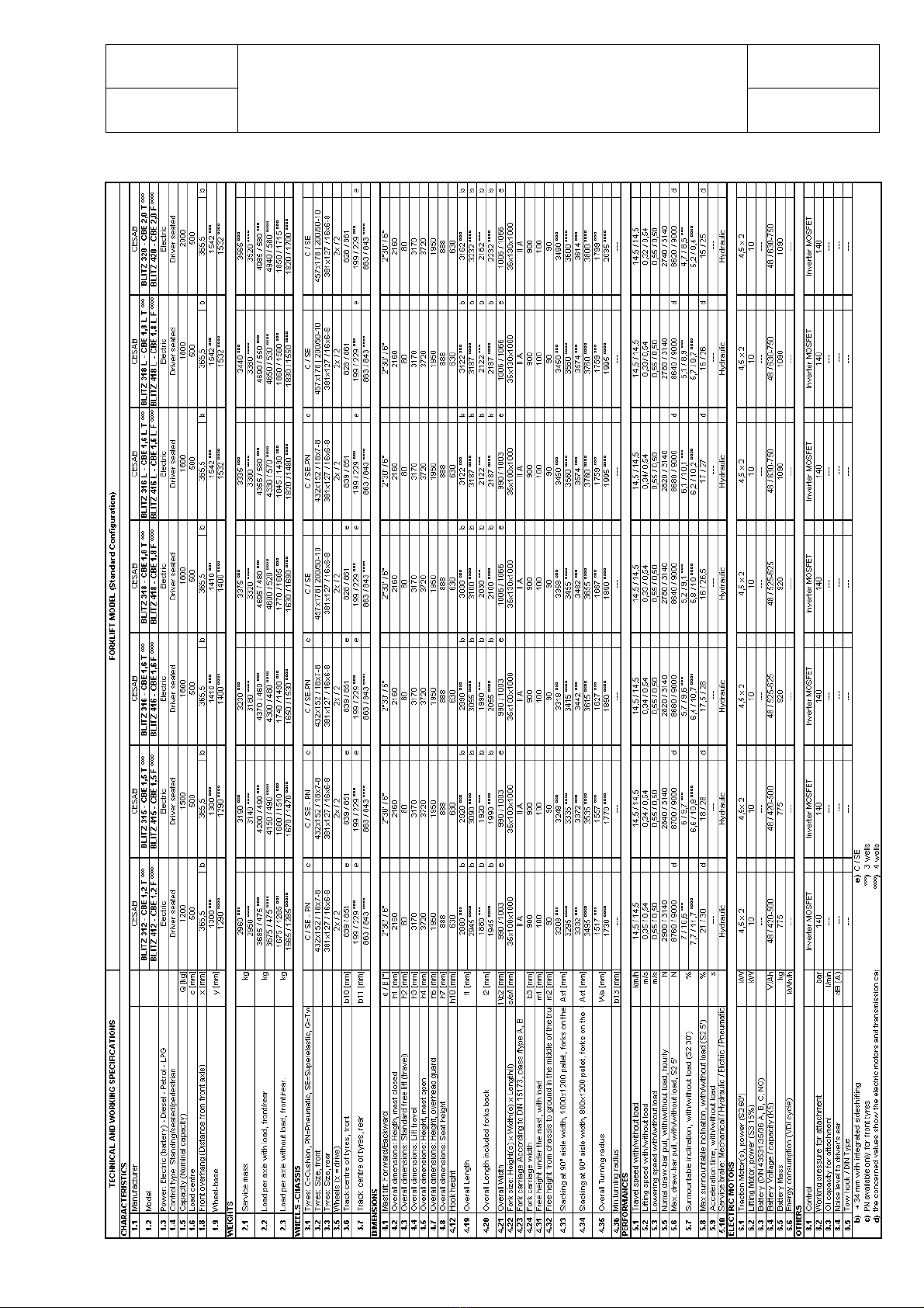
TECHNICAL DATA

chapter A
page 4
1,2 - 2,0 t A.C.
SERVICE MANUAL Electric
036-0410-07
chapter A
page 5
1,2 - 2,0 t A.C.
SERVICE MANUAL
Electric
036-0410-07

chapter A
page 6
1,2 - 2,0 t A.C.
SERVICE MANUAL Electric
036-0410-07
PAGINA INTENZIONALMENTE BIANCA
INTENTIONALLY LEFT BLANK
PAGE INTENTIONNELLEMENT BLANCHE
ABSICHTLICH FREIGELASSENE SEITE
PÁGINA INTENCIONALMENTE BLANCA

chapter 0000
page 1
1,2 - 2,0 t A.C.
SERVICE MANUAL
Electric
036-0410-07
CHAPTER 0000
CHASSIS

chapter 0000
page 2
1,2 - 2,0 t A.C. SERVICE MANUAL Electric
036-0410-07
CHASSIS INDEX
TRUCK’S LAY OUT page3
PEDALS page4
DRIVE DIRECTION LEVER ON STEERING COLUMN page4
STEERING COLUMN PUSH BUTTONS page5
LOAD HANDLING COMMANDS page6
DASHBOARD page7
DASHBOARD CONTROLS page8
PLATES page 9
LIFTING OF THE TRUCK page10
chapter 0000
page 3
1,2 - 2,0 t A.C.
SERVICE MANUAL
Electric
036-0410-07
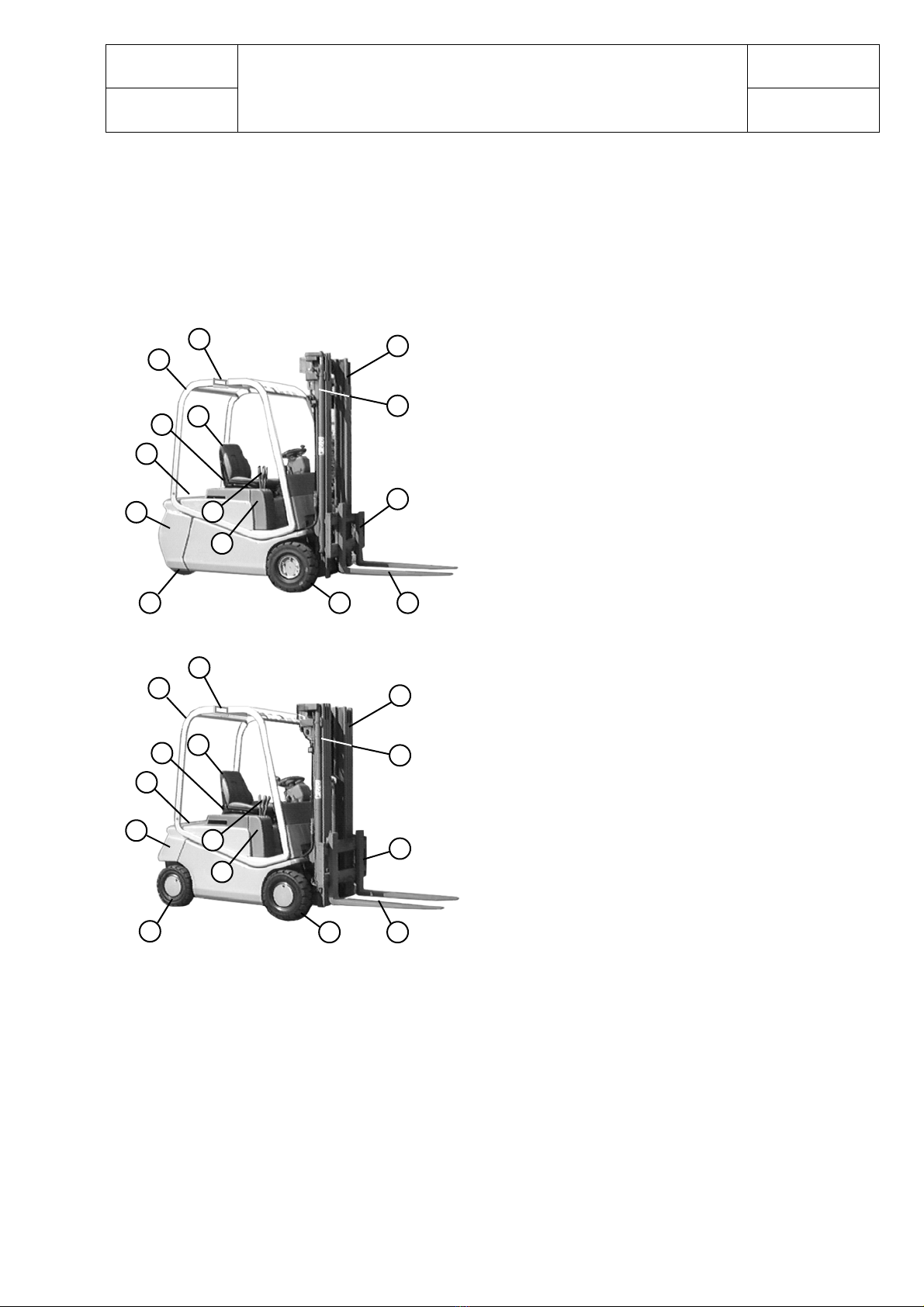
TRUCK’S LAY OUT
DESCRIPTION OF MAIN PARTS
A) Mast frame
B) Opening for lifting battery
C) Seat
D) Electronic control unit compartment
E) Counterweight
F) Hydraulic valve commands
G) Control valve cover
H) Lifting jack
I) Lifting fork carriage
J) Overhead guard
K) Present man device
M) Driven wheels
N) Steered wheels
Q) Forks
A
B
FI
E
C
D
G
N M
J
K
Q
H
B
F
E
C
D
G
N
J
K
M Q
A
I
H
chapter 0000
page 4
1,2 - 2,0 t A.C. SERVICE MANUAL Electric
036-0410-07
BD E
O
P
o
é
ê
Q
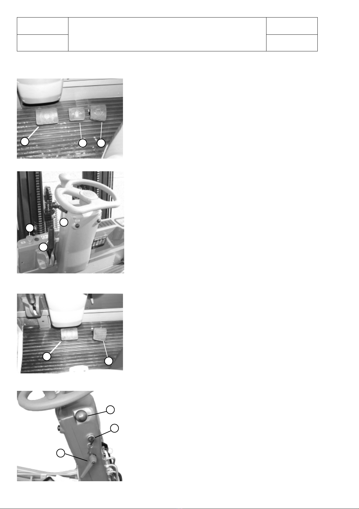
OPERATOR'S SEAT
FOOT PEDALS VERSION
FOOT DRIVE DIRECTION
(Standard version)
- Forward direction (D)
- Backward direction (E)
- Service brake pedal (B)
DRIVE DIRECTION LEVER ON STEERING
COLUMN (Alternative version)
Direction selector lever (F)
1Forward direction
0Neutral
2Backward direction
Parking brake lever (A)
Emergency push button (H)
Single drive pedal (G)
Horn push button (O)
Ignition key (P)
The steering column position can be adjusted forward or backward.
In order to do it, unloose the lever (Q) then secure the steering
column in the desired position. Do not adjust the steering column
while the truck is moving.
A
H
F
1
o
2
G
B
chapter 0000
page 5
1,2 - 2,0 t A.C.
SERVICE MANUAL
Electric
036-0410-07
M
M
N
N
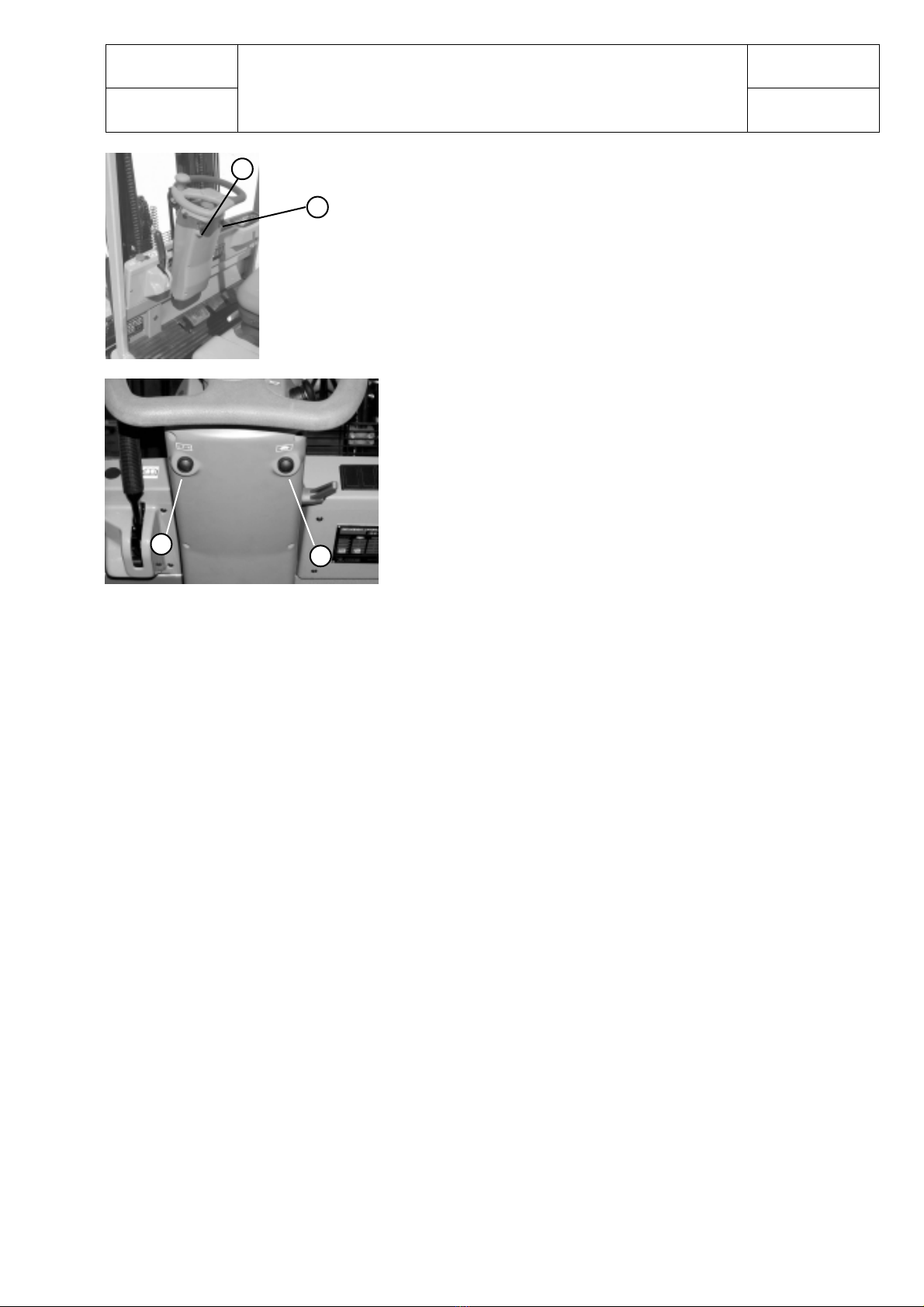
STEERING COLUMN PUSH BUTTONS
It is strongly recommended to avoid operating
both push buttons when the truck is running.
Selected setting push button (M):
P (programmable), H (high), L (low)
Speed reduction push button (N) (turtle function)
M) Selected setting push button:
at the start up, the truck is setted in the same condition as it was turned off. The available settings are:
P (programmable), H (high) or L (low).
Settings can be selected pulling the push button several times.Three leds will show the selected program
as indicated at the dashboard description page, item 11.
P: - Maximum drive speed.
- Acceleration and braking action are optimised for low energy consumption.
- Parameter change function enabled.
H: - High drive speed.
- Strong action of the traction parameters.
- Parameter change function disabled.
L: - Low drive speed.
- Soft action of the traction parameters.
- Parameter change function disabled.
N) Speed reduction push putton:
it limits the maximum drive speed of the truck by the set percentage ( from 10% up to 90% ). See
chapter 5000 (Parameter change function, DualAC2 traction unit) paragraph “CUTBACK SPEED”.
chapter 0000
page 6
1,2 - 2,0 t A.C. SERVICE MANUAL Electric
036-0410-07
3
12
A
L
B
C
H K J
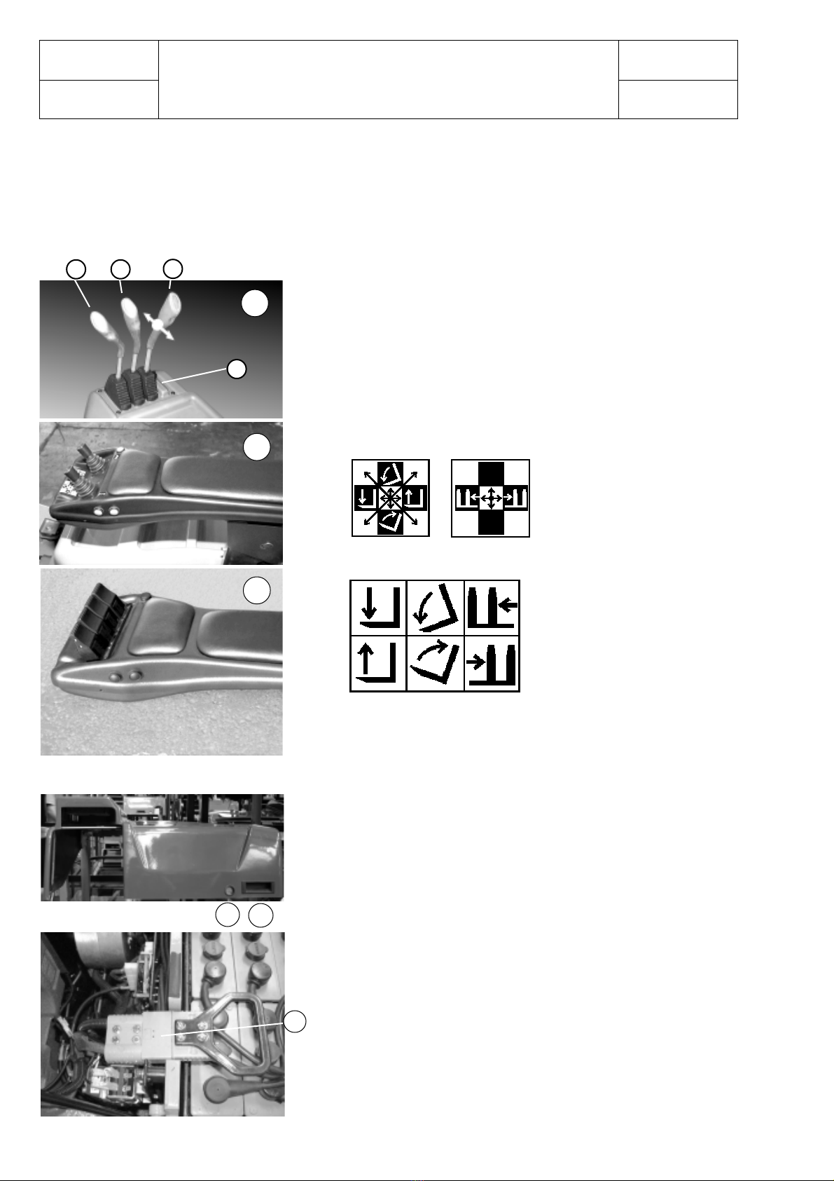
The truck can be equipped with three types of commands for load handling
CONTROL VALVE VERSION (A)
JOYSTICK VERSION (B)
FINGERTIPS VERSION (C)
Levers unit
H) Lifting control lever (yellow cap)
K) Tilting control lever (green cap)
J) Sideshift control lever (red cap)
L) Device control lever (optional) (black cap)
Functions
- Handle for a better opening / closing (1)
- Hook with opening button(2)
Battery plug fixing position
- Battery Plug (3)
BATTERY COVER
LOAD HANDLING COMMANDS

chapter 0000
page 7
1,2 - 2,0 t A.C.
SERVICE MANUAL
Electric
036-0410-07
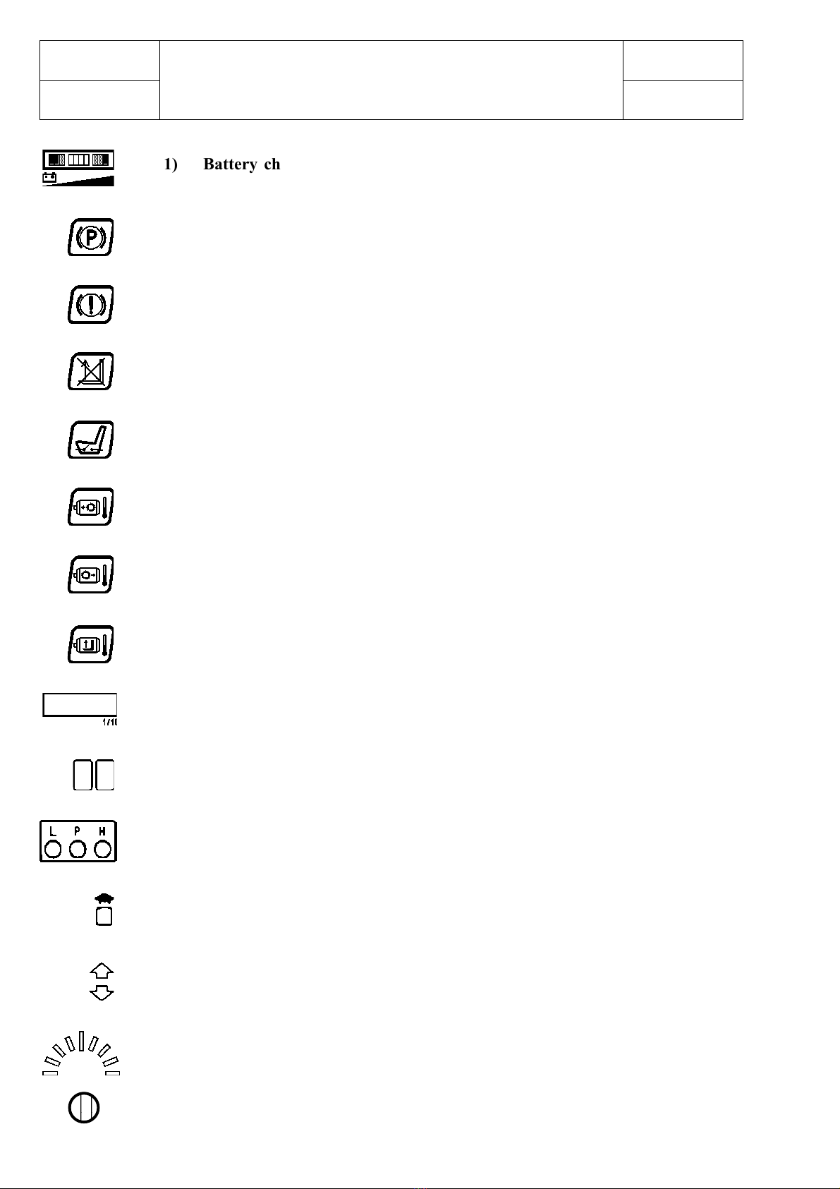
The dashboard consists of a series of instruments and warning lights to check the correct operation of
the truck.
DASHBOARD
1) Battery charge status indicator.
2) Parking brake ON warning light.
3) Brake fluid low level warning light.
4) Lifting speed reduction due to flat battery.
5) “Present man device” warning light.
6) Drive left motor temperature warning light.
7) Drive right motor temperature warning light.
8) Liftingmotortemperaturewarninglight.
9) Electronic hour meter.
10) Diagnosticcodealphanumericdisplay.
11) Selectedsettingdisplay.
12) Speedreductionindication light
13) Forward/backward indication lights
14) Steeringindicationdisplay
15) Lightsensor
8
14
121110 7
4
13
32115 56
9
chapter 0000
page 8
1,2 - 2,0 t A.C. SERVICE MANUAL Electric
036-0410-07
1234
1234
1234
1) Battery charge status indicator:
This bar consists of 3 green LEDS on the right side, 4 orange LEDS in the
middle and 3 red LEDS on the left side; when the battery is charged the
first green LED on the right is On; while the battery discharges, the LEDS
turn On or Off, one per time, from the right to the left according with the
battery charging status. When the battery is 80% discharged, the first red
LED on the left is On, the display (10) shows the alarm code 1C so the
battery must be recharged (reserve). There is an indication on the dashboard
(4) and thelifting speed is reduced because there is a current cutback by
50%. The battery charge indicator does not rearm if the battery charging
status is between 70% and 100%. It can be adjusted (see at chapter 5000).
2) Parking brake ON warning light
3) Brake fluid low level warning light:
This warning light comes ON when the level of brake fluid in the tank has
reached the minimum level.
4) Lifting speed reduction due to flat battery
5) ”Present man device” warning light:
The pilot light comes ON when the driver leaves the driving seat without
switching OFF the truck; under these conditions, the traction and the lifting
movement are disabled.
6) Drive left motor temperature warning light:
lights up when the temperature is 140°C.
7) Drive right motor temperature warning light:
lights up when the temperature is 140°C.
8) Lifting motor temperature warning light:
lights up when the temperature is 140°C.
9) Electronic hour meter:
It is activated by insertion of the ignition key and it conts the real working
time of the truck. It shows the working hoursand hours fractions (in tenth).
It can be adjusted (see chapter 5000, dashboard map)
10) Diagnostic code alphanumeric display:
When a malfunction occurs in the truck, this display identifies the error
through a corresponding code (see Alarm function chapter 5000).
11) Selected setting display:
Indicates the running setting selected: L (low), P (programmable), H (high):
12) Speed reduction indication light:
When the reduction speed is selected the blue light is on.
13) Forward/backward indication lights.
14) Steering indication display.
15) Light sensor:
It changes automatically the light intensity of the LEDS in the dashboard
according to the light of the environment.
DASHBOARD CONTROLS
1
2
3
4
5
6
7
8
9
10
11
12
13
14
15
chapter 0000
page 9
1,2 - 2,0 t A.C.
SERVICE MANUAL
Electric
036-0410-07
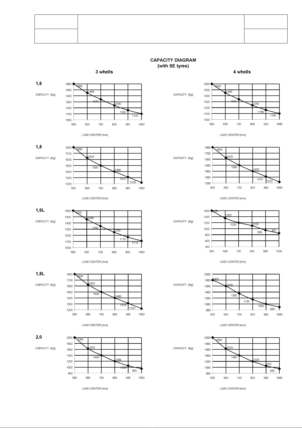
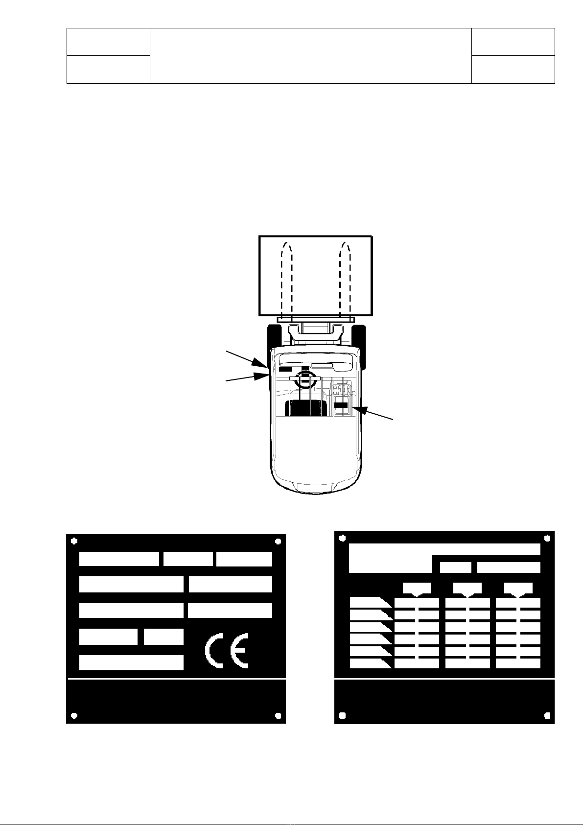
LOAD PLATE
It identifies the load capacity with a load center
of 500 mm (except for different indications)
IDENTIFICATION PLATE
It identifies the lift truck technical data
B
Cod. 0312004
CARRELLI ELEVATORI S.p.A.
via Persicetana vecchia, 10
40132 - Bologna - Italia
MODELType MOTOR RATED CAPACITY
SERIAL N° DRAW-BAR PULL (1h)
SERVICE MASS
BATTERY MASS
MANUFACT. YEAR TENSION
kW k g
N
Without
Battery kg
kg
min. kg
max.
V
CESAB LDT
Bevan Way
Smethwick - Warley
West Midla 1ds B66 1BZ
A
CAPACITY PLATE
ATTACHMENT OR SPECIAL CONDITION OF USE
TYRES SERIAL N°
CENTER OF LOAD DISTANCE mm
LIFT HEIGHT
mm
DERATED CAPACITY Kg
Cod. 0312005
PLATES
A IDENTIFICATION PLATE
B CAPACITY PLATE
The plates positions, as shown in the picture, are refered to the standard fork lift trucks; those positions
can be modified in case of special truck configuration.
B (1,2 - 1,5 t)
B (1,6 - 2,0 t)
A

chapter 0000
page 10
1,2 - 2,0 t A.C. SERVICE MANUAL Electric
036-0410-07
LIFTING OF THE TRUCK
TYPE WHEELS TRUCK WEIGHT WITH WEIGHT ONAXLES WITHOUT LOAD
t. STANDARD BATTERY (FRONT / REAR)
1.2 3 2960 kg 1675 / 1285 kg
1.5 3 3190 kg 1680 / 1510 kg
1.6 3 3230 kg 1740 / 1490 kg
1.8 3 3375 kg 1770 / 1605 kg
2.0 3 3565 kg 1850 / 1715 kg
1.6L 3 3335 kg 1845 / 1490 kg
1.8L 3 3440 kg 1860 / 1580 kg
1.2 4 2950 kg 1665 / 1285 kg
1.5 4 3140 kg 1670 / 1470 kg
1.6 4 3180 kg 1650 / 1530 kg
1.8 4 3320 kg 1630 / 1690 kg
2.0 4 3520 kg 1820 / 1700 kg
1.6L 4 3300 kg 1820 / 1480 kg
1.8L 4 3380 kg 1830 / 1550 kg
A
B
A
If the truck is equipped with mudguard extensions, the chains can
be hooked only after the extensions disassembling.
HOOK ATTACHMENT POINTS FOR LIFTING THE TRUCK
The hooking points are shown on the carriage with the symbol shown on
the side (see picture).
LIFTING OF THE FORKLIFT TRUCK WITH OVERHEAD
GUARD
The following equipments must be used to lift the forklift truck with
overhead guard (standard):
- N° 2 slings (A): in accordance with DIN B2N -UNI 9531,
minimum length 9 m and capacity of 2800 kg.
LIFTING OF THE FORKLIFT TRUCK WITH CABIN
The following equipments must be used to lift the forklift truck with
cabin:
- N° 2 slings (A): in accordance with DIN B2N -UNI 9531,
minimum length 9 m and capacity of 2800 kg.
- N° 2 upper brackets (B) to hold the chains.
It is important to remember that the chains or slings length must be
sufficient to lift the truck in a horizontal position, with the lifting angles
(ß) ≤45° with respect to the vertical lifting line. Ensure that the chains
or slings are protected where it comes into contact with edges, then
arrange the chains or slings on the truck so that it remains in a horizontal
position during the entire lifting operation.
Make sure that there are no personnel in the vicinity of the truck, before
carrying out the lifting operation.
If any maintenance operations need to be performed on the truck in a
raised position, the vehicle must be rested on appropriate
supports, sufficient to bear the overall weight of the vehicle, keeping the
chains or slings taut.
This manual suits for next models
27
Table of contents
Other CESAB Forklift manuals


Popular Forklift manuals by other brands


Strongway
Strongway 61134 owner's manual

Lift-Rite
Lift-Rite LCF55 Owner's Manual, Operating Instructions Manual, and Replacement Parts Manual

Manitou
Manitou MSI20 T 4ST3B Operator's manual

RC4WD
RC4WD VV-JD00055 quick start guide

Clark
Clark CER10 Operation and maintenance manual

Hyster
Hyster T5ZAC PERIODIC MAINTENANCE